Kenwood TK-880 Service Manual
Uhf fm transceiver
Hide thumbs
Also See for TK-880:
- Service manual (75 pages) ,
- Programming instructions manual (10 pages) ,
- Instruction manual (49 pages)
Table of Contents
Advertisement
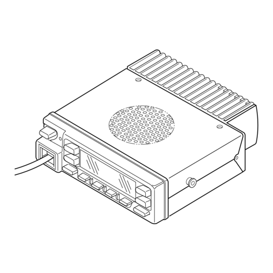
UHF FM TRANSCEIVER
TK-880/H
SERVICE MANUAL
SUPPLEMENT
This service manual applied to products with 30200001 or subsequent serial numbers.
In terms of the products with the serial numbers earier than 30200001, refer to the TK-880/H
service manual as per part No. B51-8462-10.
GENERAL ................................................................. 2
OPERATING FEATURES ......................................... 3
REALIGNMENT ...................................................... 15
INSTALLATION ...................................................... 20
CIRCUIT DESCRIPTION ......................................... 28
SEMICONDUCTOR DATA ..................................... 33
DESCRIPTION OF COMPONENTS ....................... 35
PARTS LIST ............................................................ 37
EXPLODED VIEW .................................................. 48
PACKING ................................................................ 49
Microphone
(T91-0621-05)
Cabinet (Top)
(A01-2165-13)
Key top
(K29-5284-02)
CONTENTS
ADJUSTMENT ....................................................... 50
PLL/VCO (X58-4550-XX) .................................. 58
TX-RX UNIT (X57-6450-XX) (A/2) ................... 59
TX-RX UNIT (X57-6450-XX) (B/2) .................... 65
SCHEMATIC DIAGRAM ........................................ 69
BLOCK DIAGRAM.................................................. 77
LEVEL DIAGRAM................................................... 80
TERMINAL FUNCTION ......................................... 82
SPECIFICATIONS................................................... 83
© 2001-5 PRINTED IN JAPAN
B51-8582-00 ( N ) 1370
Panel assy
(A62-0991-03)
Advertisement
Table of Contents

Related Manuals for Kenwood TK-880


Summary of Contents for Kenwood TK-880
-
Page 1: Table Of Contents
B51-8582-00 ( N ) 1370 This service manual applied to products with 30200001 or subsequent serial numbers. In terms of the products with the serial numbers earier than 30200001, refer to the TK-880/H service manual as per part No. B51-8462-10. -
Page 2: General
TK-880/H GENERAL 3-2. Testing INTRODUCTION The radio should be tested complete with all cabling and SCOPE OF THIS MANUAL accessories as they will be connected in the final installa- This manual is intended for use by experienced techni- tion. Transmitter frequency, deviation, and power output... -
Page 3: Operating Features
5. INSTALLATION PLANNING – CONTROL STATIONS 1. Operation Features 5-1. Antenna system The TK-880/880H is a UHF FM radio designed to operate Control station. The antenna system selection depends in both trunking format (LTR model) and conventional for- on many factors and is beyond the scope of this manual. -
Page 4: Operating Features
TK-880/H OPERATING FEATURES 2-2. Programmable Keys • DTMF ID (BOT) The FPU (KPG-49D) enables programmable keys to se- In conventional mode, if you press this key, a predeter- lect the following functions. mined DTMF ID (Begin of TX) will be sent automatically. - Page 5 TK-880/H OPERATING FEATURES • Message mode • Scan del/add 1) Trunking format Press this key to enter the message mode. (See “Alpha- numeric Two-way Paging Function” for details) Used to select whether system scan routines are used during system scan. Each pressing of the key (to ON) •...
-
Page 6: Scan Operating
TK-880/H OPERATING FEATURES 2-3. Front Panel Displays and Indicators Handset indicator Sub display The handset indicator ( ) appears when the selected group is programmed as telephone IDs (Trunking format). Displays the system, channel and group numbers. Also In conventional format, the handset indicator ( ) appears displays various functions, such as TA. - Page 7 TK-880/H OPERATING FEATURES System lockout • Selected + Talkback revert The system lockout feature is used to lock systems out If the system/group was changed while scanning, the of the scan sequence, and can be selected by programming newly selected system/group. The transceiver “talks back”...
- Page 8 TK-880/H OPERATING FEATURES SCAN start condition 2) Priority + talkback One or more non-priority channels must be added to all The transceiver reverts to the priority channel. channels that can be scanned. The transceiver must be in If you press PTT during a resume timer (dropout delay normal receive mode (PTT off).
- Page 9 TK-880/H OPERATING FEATURES Sub LCD display Horn alert You can use 3-digit the display to display the system In trunking format, horn alert can be set to on or off for number, channel number or group number. It is useful each group.
- Page 10 TK-880/H OPERATING FEATURES 4-2. Trunking Format Transmit inhibit Call indicator The transceiver can be programmed with a transmit in- The call indicator can be programmed for each group. In hibit block of ID codes. If an ID code within this block is...
-
Page 11: Option Signalling
T h e A l p h a n u m e r i c T w o - w a y P a g i n g F u n c t i o n will flash. (FleetSync™) is a KENWOOD proprietary protocol. It en- While option signalling matches (or if option signalling is ables a variety of paging functions. - Page 12 TK-880/H OPERATING FEATURES Selective Call (SELCALL) • Automatic status response This is a voice call to a particular individual or group of If you pre-select a status number and leave the radio in stations. the Status Mode, it can automatically respond with the se- lected status number upon request from the base station.
- Page 13 • Caller ID display 2) MAP HEADER KW1 ($PKLDS) PTT ID is displayed on LCD. This is a Kenwood original sentence which consists of “$GPGLL + Fleet + ID + Status”. This item should be set • Call alert (Continuous) according to your PC application.
-
Page 14: Audible User Feedback Tones
TK-880/H OPERATING FEATURES • ACK delay time Group Call Tone ACK Delay Time is the amount of time from the end of Sounds when a group call with the correct DTMF/2-tone receiving a data to the beginning of sending an option signalling is received, repeats 7 times. - Page 15 TK-880/H OPERATING FEATURES / REALIGNMENT Delay Tone (Trunking Format) 1. Modes This tone is output when the PTT button is pressed and the repeater is accessed three times or more to indicate User mode connection with the repeater is delayed. This tone is the...
-
Page 16: Realignment
PC or compatible) with the interface cable (KPG-46). (Con- model type, when it is written into the flash memory. nection is the same as in the PC Mode.) • Change the TK-880/880H to PC mode, then attach the interface cable. 6-3. Programming 1. -
Page 17: Clone Mode
The operation is as follows (the transmit radio is the master and the receive radio is a slave). 1. Turn the master TK-880/880H power ON with the [C] key held down. If the password is set to the TK-880/880H, the TK-880/880H displays “CLONE LOCK”. -
Page 18: Self Programming Mode
TK-880/H REALIGNMENT The setup items fro channel setting mode are listed be- 8. Self Programming Mode low. Write mode for frequency data and signalling etc. Mainly used by the person maintaining the user equipment. Setup function Display Remarks (3 character) 8-1. - Page 19 TK-880/H REALIGNMENT 10-1. Flow Chart 10. Function Setting Mode All channels can be set up together in the action mode by Self programming mode using the panel keys. • Pressing [D] while “SELF PROG” is displayed will change to function setting mode.
-
Page 20: Installation
TK-880/H INSTALLATION 1-2. KCT-19 Accessory Port Function 1. Accessory Connection Cable No. (A) No. (B,C,D,E) Name Function Note (KCT-19 : Option) External hook input The KCT-19 is an accessory connection cable for con- BUSY System busy output necting external equipment. The connector has 15 pins and the necessary signal lines are selected for use. - Page 21 TK-880/H INSTALLATION 1-3. Data Equipment Connection The jumpers must be set to either one for each function. Otherwise, the radio will not work properly. AHK/BUSY R64 (0Ω) R18 (0Ω) Function BUSY System busy output indicates if no TX-RX unit (A/2)
- Page 22 TK-880/H INSTALLATION 3. Optional Board Terminal Connector Function name Terminal is for mounting the option board are provided at the TX-RX unit (A/2) and TX-RX unit (B/2). The table below O Squelch signal output. Signal logic shows the correspondence between the board and termi- type can select “Carrier operate...
- Page 23 TK-880/H INSTALLATION TX-RX unit (A/2) Foil side view KCT-19 Contact KCT-18 Fig. 3 4-2. Modifying the Transceiver TX-RX unit (A/2) Modify the transceiver as follows to turn the power or Component side view the Horn Alert or Manual Relay function on and off with the ignition key.
- Page 24 6. Interface Cable (KCT-31 : Option) The KCT-29 connection cable kit is used to connect the The KCT-31 is a RS-232C interface cable for LMR mobile TK-880/880H transceiver to the KPG-1A Modem GPS Re- radios, TK-880/880H. ceiver or the KPG-1B Modem GPS Controller.
- Page 25 When the COM1 is used. When the COM2 is used. Fig. 9 Note : · The modification must be applied to the TK-880/880H · Enable the serial port function on the terminal. transceivers with a serial number of 30200000 or smaller ·...
- Page 26 8. Fitting the Control Panel Upside Down 7-1. Installing the KAP-1 in the Transceiver The TK-880/880H control panel can be fitted upside down, so the transceiver can be mounted with its internal The Horn Alert (max. 2A drive) and Public Address func- speaker (in the upper half of the case) facing down in your tions are enabled by inserting the KAP-1 W1 (3P;...
-
Page 27: External Speaker
TK-880/H INSTALLATION 9-2. KES-4 : Option 6. Rotate the control panel 180 degrees and mount it on the transceiver. Refit the two halves of the case to complete The KES-4 is an external speaker used with the acces- installation. (Fig. 13) sory connection cable. -
Page 28: Circuit Description
Wide : L Narrow : H low-pass filter and a transmission/reception selection diode switch (TK-880 : D209, D210, D211, TK-880H : D402, D210, D211) and goes to the front end of the receiver. The front- Fig. 3 Wide/Narrow changeover circuit... - Page 29 VCO/PLL Circuit unit (A/2) is input to the D/A converter (IC5). The AFO out- The TK-880/880H has a VCO for the transmitter and a put level is adjusted by the D/A converter. The signal output VCO for the receiver in a sub-unit (A1). They are housed in a...
- Page 30 TK-880/H CIRCUIT DESCRIPTION Unlock Circuit Q17 turns the PC signal on or off using 8T so that the circuit works only during transmission. With stability at low During reception, the TR signal goes high, the KEY signal power in mind, Q29 turns off to optimize the detection volt- goes low, and Q10 turns on.
- Page 31 Key Matrix Circuit through two low-pass filters of IC501, goes to LSDI of the The TK-880/880H front panel has ten keys. Each of them CPU (IC511) to decode QT, DQT, and LTR. The DTMF signal is connected to a cross point of a matrix of the KEY1 to KEY7 is decoded by a dedicated IC (IC507) and the resulting signal ports of the microprocessor.
- Page 32 TK-880/H CIRCUIT DESCRIPTION Horn Control Power Supply Circuit The horn switch, consisting of Q4, Q5, and Q6, controls When the POWER switch on the TX-RX unit (B/2) is the horn relay. It is supplied by the dealer to provide the pressed, the PSW signal goes low.
-
Page 33: Semiconductor Data
TK-880/H SEMICONDUCTOR DATA Microprocessor : 30622M8A-4F9GP (TX-RX Unit (B/2) IC511) Terminal function Pin No. Name Function Pin No. Name Function LSDOUT Low speed data output. RFCLK Common clock output. (TX-RX unit A/2) HSDOUT High speed data output. – Not used. - Page 34 TK-880/H SEMICONDUCTOR DATA Terminal function (TX-RX unit (A/2) IC7) Shift Register : BU4094BCFV Pin No. Port Name Function Terminal function (TX-RX unit (B/2) IC508) Strobe Pin No. Port Name Function Data Strobe Clock Data HORN Horn alert. H : ON, L : OFF / Clock Auxiliary A.
-
Page 35: Description Of Components
TK-880/H DESCRIPTION OF COMPONENTS TX-RX Unit (X57-6450-XX) (A/2) Ref. No. Use / Function Operation / Condition -10 : K -11 : K2 -12 : K3 -13 : HK -14 : HK2 -15 : HK3 APC pre-driver APC control Ref. No. - Page 36 TK-880/H DESCRIPTION OF COMPONENTS Ref. No. Use / Function Operation / Condition Ref. No. Use / Function Operation / Condition D200 Over voltage D501 Surge absorption protection D502 Over current D203~206 Vari-cap tune protection D207 Usable temperature D503 Surge absorption...
-
Page 37: Parts List
TK-880/H PARTS LIST CAPACITORS CC 45 TH 1H 220 J • Capacitor value Color* CC45 010 = 1pF 0 = 22pF 100 = 10pF 1 = Type … ceramic, electrolytic, etc. 4 = Voltage rating Multiplier 101 = 100pF 2 = Shape … round, square, ect. - Page 38 TK-880/H PARTS LIST L : Scandinavia K : USA P : Canada New Parts. indicates safety critical components. Y : PX (Far East, Hawaii) T : England E : Europe Parts without Parts No. are not supplied. Y : AAFES (Europe)
- Page 39 TK-880/H PARTS LIST TX-RX UNIT (X57-6450-XX) Desti- Desti- Ref. No. Address Parts No. Description Ref. No. Address Parts No. Description parts nation parts nation CK73FB1E103K CHIP C 0.010UF C133 C92-0720-05 CHIP-ELE 100UF 25WV CK73GB1E103K CHIP C 0.010UF C134 CK73FB1E224K CHIP C 0.22UF...
- Page 40 TK-880/H PARTS LIST TX-RX UNIT (X57-6450-XX) Desti- Desti- Ref. No. Address Parts No. Description Ref. No. Address Parts No. Description parts nation parts nation C222-224 CC73GCH1H070D CHIP C 7.0PF C272 C93-0556-05 CHIP C 6.0PF C222,223 CC73GCH1H050C CHIP C 5.0PF K2,HK2...
- Page 41 TK-880/H PARTS LIST TX-RX UNIT (X57-6450-XX) Desti- Desti- Ref. No. Address Parts No. Description Ref. No. Address Parts No. Description parts nation parts nation C432 CK73FB1E103K CHIP C 0.010UF HK,HK2 C568 C92-0712-05 CHIP-TAN 22UF 6.3WV C432 CK73FB1E103K CHIP C 0.010UF...
- Page 42 TK-880/H PARTS LIST TX-RX UNIT (X57-6450-XX) Desti- Desti- Ref. No. Address Parts No. Description Ref. No. Address Parts No. Description parts nation parts nation E40-5982-05 FLAT CABLE CONNECTOR L501-508 L92-0138-05 FERRITE CHIP CN501 E40-5823-05 FLAT CABLE CONNECTOR L77-1777-05 TCXO (16.8M)
- Page 43 TK-880/H PARTS LIST TX-RX UNIT (X57-6450-XX) Desti- Desti- Ref. No. Address Parts No. Description Ref. No. Address Parts No. Description parts nation parts nation RK73GB1J221J CHIP R 1/16W R140 R92-1252-05 CHIP R 0 OHM R63-65 R92-1252-05 CHIP R 0 OHM...
- Page 44 TK-880/H PARTS LIST TX-RX UNIT (X57-6450-XX) Desti- Desti- Ref. No. Address Parts No. Description Ref. No. Address Parts No. Description parts nation parts nation R233 RK73GB1J470J CHIP R 1/16W R422 R92-1252-05 CHIP R 0 OHM R234 RK73GB1J270J CHIP R 1/16W...
- Page 45 TK-880/H PARTS LIST TX-RX UNIT (X57-6450-XX) Desti- Desti- Ref. No. Address Parts No. Description Ref. No. Address Parts No. Description parts nation parts nation R571,572 R92-1252-05 CHIP R 0 OHM R677 RK73GB1J223J CHIP R 1/16W R573 RK73GB1J104J CHIP R 100K...
- Page 46 TK-880/H PARTS LIST TX-RX UNIT (X57-6450-XX) PLL/VCO (X58-4550-XX) Desti- Desti- Ref. No. Address Parts No. Description Ref. No. Address Parts No. Description parts nation parts nation D503-505 HSB123 DIODE DTC114EE DIGITAL TRANSISTOR D507 DAN202U DIODE DTA114EE DIGITAL TRANSISTOR D508,509 MA742...
- Page 47 TK-880/H PARTS LIST PLL/VCO (X58-4550-XX) Desti- Desti- Ref. No. Address Parts No. Description Ref. No. Address Parts No. Description parts nation parts nation C117 CK73GB1H471K CHIP C 470PF Q104,105 2SC4081 TRANSISTOR C118 CC73GCH1H020B CHIP C 2.0PF K2,HK2 Q106 2SC4226(R24) TRANSISTOR...
-
Page 48: Exploded View
TK-880/H EXPLODED VIEW Parts with the exploded numbers larger than 700 are not supplied. -
Page 49: Packing
TK-880/H PACKING 42 Microphone 11 DC cord (T91-0621-05) (E30-3339-05) 31 Protection bag (H25-0720-04) 17 Fuse (F51-0016-05) : TK-880 (F51-0017-05) : TK-880H 5 Cap (B09-0235-05) 35 Bracket (J29-0627-23) 30 Inner packing case (H12-1391-03) 34 Holder (J19-1584-05) 39 Screw set 29 Polystyrene foamed fixture... -
Page 50: Adjustment
TK-880/H ADJUSTMENT Frequency and Signalling Test Mode The set has been adjusted for the frequencies shown in Test Mode Operating Features the following table. When required, re-adjust them follow- This transceiver has a test mode. To enter test mode, ing the adjustment procedure to obtain the frequencies you press [A] key and turn power on. - Page 51 TK-880/H ADJUSTMENT LCD display (Tuning mode) Press [SCN], now in tuning mode. Use [B] button to write tuning data through tuning modes, and [System Up/ F R E Q Down] : Trunking format, [Group Up/Down] : Conventional format to adjust tuning requirements (1 to 256 appears on...
- Page 52 TK-880/H ADJUSTMENT Test Equipment Required for Alignment Test Equipment Major Specifications 1. Standard Signal Generator Frequency Range 400 to 520MHz (SSG) Modulation Frequency modulation and external modulation Output –127dBm/0.1µV to greater than –7dBm/100mV 2. Power Meter Input Impedance 50Ω Operation Frequency...
- Page 53 Repair Jig (Chassis) • EEPROM Use jig (Part No. : A10-4010-02) for repairing the TK-880/ The tuning data (Deviation, Squelch, etc.) for the 880H. The jig facilitates the voltage check when the voltage EEPROM, is stored in memory. When parts are changed, on the component side TX-RX unit (A/2) is checked during readjust the transceiver.
- Page 54 TK-880/H ADJUSTMENT Receiver Section Measurement Adjustment Item Condition Specifications/Remarks Test- Unit Terminal Unit Parts Method equipment 1. Discriminator 1) Set test mode Rear TX-RX L6 AF output maximum. Maximum point +0mV, –20mV. CH : CH1 - Sig1 - Narrow panel (A/2) SSG output : –53dBm...
- Page 55 TK-880/H ADJUSTMENT Transmitter Section Measurement Adjustment Item Condition Specifications/Remarks Test- Unit Terminal Unit Parts Method equipment 1. Frequency 1) Set test mode Power meter Rear Check K,HK : 470.100MHz± 100Hz Select “FREQ” in tuning mode. F. counter panel K2,HK2 : 498.600MHz± 100Hz PTT : ON K3,HK3 : 418.100MHz±...
- Page 56 TK-880/H ADJUSTMENT Measurement Adjustment Item Condition Specifications/Remarks Test- Unit Terminal Unit Parts Method equipment 6. Modulation 1) Set test mode Power meter Rear Make the de- (Wide/Narrow) balanced MIC input : OFF Deviation panel modulation Select “BAL” in tuning mode. meter waveform neat.
- Page 57 TK-880/H ADJUSTMENT Measurement Adjustment Item Condition Specifications/Remarks Test- Unit Terminal Unit Parts Method equipment ± 50Hz (Wide/Narrow) 11. Fine LTR 1) Set test mode Power meter Rear 1.0kHz (Wide) Select “FLTR” in tuning mode. Deviation panel 0.75kHz (Narrow) “L FLTR”...
-
Page 58: Pc Board Views
TK-880/H PC BOARD VIEWS PLL/VCO UNIT (X58-4550-XX) -10 : K,HK -11 : K2,HK2 -12 : K3,HK3 Component side view J72-0618-02 C115 C119 CN101 L105 L109 L103 C104 R104 C117 C122 L107 Q105 Q106 R109 R118 Q102 R111 R110 R115 C125... -
Page 59: Tx-Rx Unit (X57-6450-Xx) (A/2)
TK-880/H PC BOARD VIEW TX-RX UNIT (X57-6450-XX) (A/2) Component side view Ref No. Address Ref No. Address Ref No. Address Ref No. Address Ref No. Address -10 : K -11 : K2 -12 : K3 -13 : HK -14 : HK2 -15 : HK3... - Page 60 TK-880/H PC BOARD VIEW TX-RX UNIT (X57-6450-XX) (A/2) Foil side view Ref No. Address Ref No. Address Ref No. Address Ref No. Address Ref No. Address Ref No. Address -10 : K -11 : K2 -12 : K3 -13 : HK -14 : HK2 -15 : HK3...
- Page 61 TK-880/H PC BOARD VIEW TX-RX UNIT (X57-6450-XX) (A/2) Component side view + Foil side Ref No. Address Ref No. Address Ref No. Address Ref No. Address Ref No. Address Ref No. Address Ref No. Address Ref No. Address -10 : K -11 : K2 -12 : K3 -13 : HK -14 : HK2 -15 : HK3...
-
Page 62: Tx-Rx Unit (X57-6450-Xx) (B/2)
TK-880/H PC BOARD VIEWS TX-RX UNIT (X57-6450-XX) (B/2) -10 : K -11 : K2 -12 : K3 -13 : HK -14 : HK2 -15 : HK3 Component side view R514 D517 R710 R517 C712 D512 R510 C527 C710 C518 C583... - Page 63 TK-880/H PC BOARD VIEW TX-RX UNIT (X57-6450-XX) (B/2) -10 : K -11 : K2 -12 : K3 -13 : HK -14 : HK2 -15 : HK3 Component side view + Foil side R520 R514 R710 D517 C607 R517 C712 MPTT...
-
Page 64: Schematic Diagram
TK-880/H Note : Components marked with a dot (·) are parts of patterun 1. SCHEMATIC DIAGRAM... - Page 65 TK-880/H SCHEMATIC DIAGRAM Note : Components marked with a dot (·) are parts of patterun 1.
-
Page 66: Block Diagram
TK-880/H TK-880/H TK-880/H BLOCK DIAGRAM... -
Page 67: Level Diagram
TK-880/H TK-880/H LEVEL DIAGRAM Receiver Section Transmitter Section... -
Page 68: Terminal Function
TK-880/H TERMINAL FUNCTION CN7 (TX-RX Unit A/2) ← → CN502 (TX-RX Unit B/2) CN101 (VCO) ← → TX-RX Unit (A/2) Pin No. Name Function Pin No. Name Function Wide/Narrow switch input. H : Wide Switched transmit input. H : Transmit TX/RX switch input. -
Page 69: Specifications
Temperature Range ......–30°C to +60°C (–22°F to +140°F) Dimensions & Weight ......TK-880 : 140 (5.51) W x 40 (1.58) H x 145 (5.73) D mm (inch), 0.94kg (2.07 lbs) TK-880H : 140 (5.51) W x 40 (1.58) H x 173 (6.84) D mm (inch), 1.05kg (2.31 lbs) - Page 70 Mechelsesteenweg 418 B-1930 Zaventem, Belgium KENWOOD ELECTRONICS FRANCE S.A. 13, Boulevard Ney, 75018 Paris, France KENWOOD ELECTRONICS U.K. LIMITED KENWOOD House, Dwight Road, Watford, Herts., WD1 8EB United Kingdom KENWOOD ELECTRONICS EUROPE B.V. Amsterdamseweg 37, 1422 AC Uithoorn, The Netherlands KENWOOD ELECTRONICS ITALIA S.p.A.