Inter-Tel 3000 Administration Manual
Inter-tel 3000 inter-tel administration manual
Hide thumbs
Also See for 3000:
- Quick reference manual (13 pages) ,
- Quick reference manual (15 pages) ,
- Getting started manual (34 pages)
Table of Contents
Advertisement
Quick Links
Download this manual
See also:
Quick Reference Manual
Advertisement
Table of Contents

Related Manuals for Inter-Tel 3000


Summary of Contents for Inter-Tel 3000
- Page 1 Inter-Tel 3000 ® Administration Manual...
-
Page 2: Table Of Contents
CONTACT DETAILS ... 12 USING THIS GUIDE ... 13 DIGITAL TELEPHONE SETS... 14 TO ADJUST THE DIGITAL TELEPHONE SET PEDESTAL ... 16 USING THE DIGITAL TELEPHONE SET DISPLAY... 17 USING THE DISPLAY KEYS TO SELECT MENU OPTIONS... 18 USING THE SCROLL KEYS... 18 USING THE CLEAR KEY “C”... - Page 3 Administrator’s Manual CUSTOMIZING YOUR DIGITAL TELEPHONE SET... 21 TO CHANGE THE LANGUAGE ON YOUR PHONE ... 21 AUTOMATIC ANSWER ... 21 TO PROGRAM A FEATURE ONTO A PROGRAMMABLE KEY ON YOUR EXTENSION ... 21 HEADSET MODE ... 22 TO SELECT A RINGING TONE ... 22 TO SET THE DISPLAY CONTRAST ...
- Page 4 TO SET UP AN INTERNAL CONFERENCE ... 36 TO SET UP AN EXTERNAL CONFERENCE ... 36 USING YOUR DIGITAL TELEPHONE SET WITH A HEADSET ... 36 TO MAKE AN INTERNAL OR EXTERNAL CALL WHEN USING A HEADSET ... 36 TO END A CALL WHEN USING HEADSET ... 36 TO ANSWER A CALL WHEN USING A HEADSET ...
- Page 5 Administrator’s Manual ... 51 OICE TO ALLOCATE A VOICE MAILBOX TO AN EXTENSION ... 51 SETTING UP VOICE MAILBOXES ... 51 TO RECORD VOICE MAILBOX GREETINGS ... 51 TO REPLAY A VOICE MAILBOX GREETING ... 52 TO SELECT THE PRIMARY OR ALTERNATE GREETING... 52 RECORDING NAMES IN VOICE MAILBOXES ...
- Page 6 TELEPHONE SETS AND THE PA ... 73 SINGLE EXTENSION PAGE ... 74 TO ANSWER A SINGLE EXTENSION PAGE CALL AT YOUR EXTENSION ... 74 TO PROTECT DIGITAL TELEPHONE SETS AGAINST PAGING ANNOUNCEMENTS ... 74 TO PREVENT EXTENSIONS FROM USING THE PUBLIC ADDRESS SYSTEM... 74 MANAGER / ASSISTANT ...
- Page 7 SENDING A HOOKFLASH WHILE ON A CALL ... 83 TO SEND A HOOKFLASH SIGNAL TO A CO OR A PBX ... 83 EXTENSION RESET ... 83 TO RESET YOUR DIGITAL TELEPHONE SET ... 83 SETTING THE TIME AND DATE ... 83 MUSIC-ON-HOLD OPTIONS ... 84 TO SUPPLY MUSIC, TONE OR SILENCE TO CALLERS ON HOLD...
- Page 8 ADDITIONAL PROGRAMMING OPTIONS ... 93 SYSTEM LANGUAGE ... 93 TO CHANGE THE PROGRAMMING EXTENSION ... 93 TO CHANGE THE SYSTEM PROGRAMMING PASSWORD ... 93 TO CONFIGURE UNEQUIPPED LINE INTERFACES ... 94 TO CONFIGURE DISCONNECTED EXTENSIONS ... 94 TO EXAMINE SYSTEM PASSWORDS... 94 TO CONFIGURE LINE KEY LIGHTS ...
- Page 9 Administrator’s Manual INCOMING CALLS ONLY WHEN T1 IS PROGRAMMED... 111 INCOMING CALLS ONLY WHEN PRI IS PROGRAMMED ... 111 OUTGOING GROUPS ... 112 OUTGOING GROUPS PROGRAMMING WHEN T1 IS PROGRAMMED ... 112 OUTGOING GROUPS WHEN PRI IS PROGRAMMED ... 112 LCR CODES ...
-
Page 10: Fcc Information
(as determined by the total RENs) contact the local telephone company. If this equipment Inter-Tel 3000 causes harm to the telephone network, the telephone company will notify you in advance that temporary discontinuance of service can be required. But if advance notice isn’t practical, the telephone company will notify the customer as soon as possible. -
Page 11: Customer Owned Coin/Credit Card Phones
The circuitry from the certified unit to the telephone line must be provided in wiring that carries no other circuitry unless specifically allowed by the rules (such as PC and PR leads). PC board traces carrying tip and ring leads shall have sufficient spacing to avoid surge breakdown. - Page 12 The user can find the following booklet prepared by the FCC helpful: “How to Identify and Resolve Radio-TV Interference Problems”. This booklet is available from the U.S. Government Printing Office, Washington, D.C. 20402, Stock No. 004-000-00398-5. If RFI problems persist, contact Inter-Tel Customer Support.
-
Page 13: Safety Regulations
SAFETY REGULATIONS Important Safety Instructions The following safety information is reprinted from UL 60950:2000. When using your telephone equipment, basic safety precautions should always be followed to reduce the risk of fire, electric shock, and injury to persons, including the following: Read and understand all instructions. -
Page 14: Save These Instructions
If the product has been dropped or the cabinet has been damaged. If the product exhibits a distinct change in performance. Avoid using a telephone (other than a cordless type) during an electrical storm. There can be a remote risk of electric shock from lightning. -
Page 15: Limited Warranty
Administrator’s Manual LIMITED WARRANTY For a period of 18 months from the date of purchase, Inter-Tel® warrants the Equipment (except for fuses and lamps) to be free from defects in material, workmanship, or both, and to comply with specifications for the Equipment, as set forth in the Installation Manual. -
Page 16: Software License Agreement
“Authorized Dealer” means an individual or entity currently authorized in writing by agreement and in good standing with Inter-Tel entitling the dealer to sell or license the specific Software covered by this license. “Software” means: the computer programs accompanying this License (including, but not limited... -
Page 17: Non-Permitted Uses
Inter-Tel software program(s). The Agreement is also terminated if You fail to comply with any term or condition of this Agreement. You agree to return to Inter-Tel the original diskette(s) and other applicable software media and all copies of the Inter-Tel Software program(s) upon such termination. -
Page 18: Limits Of Liability
This Agreement shall be governed by the laws of the State of Arizona. No failure or delay on the part of Inter-Tel to enforce its rights hereunder shall operate as a waiver of any right. -
Page 19: Government Restricted Rights
(1) (ii) of the Rights in Technical Data and Computer Software clause at DFARS 252.227-7013 (Oct. 1988) and FAR 52.227-14 and 52.227-19 (June 1987). Contractor is Inter-Tel Integrated Systems, Inc., Chandler, Arizona 85226. -
Page 20: Introduction
• The Inter-Tel 3000 can accommodate up to 20 Central Office (CO) Lines. • The Inter-Tel 3000 can be equipped with a T1 module providing up to 24 T1 or 23 Primary Rate ISDN channels. • The Inter-Tel 3000 is modular in construction. It is upgraded by adding various system modules. -
Page 21: System Options
Remote maintenance and programming Remote diagnostics Contact Details “Sales and Service” numbers can be programmed into the system under “System” programming. When entered, these numbers can be dialed using the Directory key on the digital telephone sets. Capacity Notes 20 Lines total... -
Page 22: Using This Guide
Administrator’s Manual USING THIS GUIDE This Administrator’s Manual is your guide to using the Inter-Tel 3000 system. It also explains how to program system settings using a digital telephone set. In describing the various system features, dialing codes are given which are used to activate features with standard analog phones and the Inter-Tel cordless phone. -
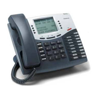
Page 23: Digital Telephone Sets
DIGITAL TELEPHONE SETS There are two digital telephone sets, one with eight and the other with sixteen programmable keys. All of the digital telephone sets are highly featured display telephones. They all have a four-line display that contains prompts, and menus with selectable options. This unique menu-driven interface makes the system simple to use, and no codes are needed to program and activate features. - Page 24 Inter-Tel 3000 Administrator’s Manual Sixteen Key Digital Telephone Set with DSS Mute Key Speaker Key/Light Handset Data Socket and Headset Socket (underneath) Programmable Keys Sixteen Key Digital Telephone Set Handset Data Socket and Headset Socket (underneath) Numeric Keypad Volume Keys...
-
Page 25: To Adjust The Digital Telephone Set Pedestal
To adjust the Digital Telephone Set Pedestal • The pedestal can be mounted on two locations on the base of the telephone. • The locations provide two angles 20 or 35-degrees. • To remove the pedestal, press the clip down as shown. -
Page 26: Using The Digital Telephone Set Display
System Programming menus from the wrong extension will result in the prompt “Programming refused”. • When your digital telephone set is not in use, its display shows the time and date on the top line. To set the time and date, see page 83 •... -
Page 27: Using The Display Keys To Select Menu Options
Using the Display Keys to Select Menu Options The six display keys, located on each side of the display, are pressed to select the options shown on the display. This will either activate a feature, cause another menu to be displayed, or select an item from a list. -
Page 28: Using The Programmable Keys / Line Keys
The line keys incorporate a light, which is lit on all digital telephone sets when the associated line is selected. The light is green on the digital telephone set using the line and red on all others. When a call on a line is put on hold the associated line key light flashes on all digital telephone sets, unless the programming is changed as detailed on page 95. -
Page 29: Using The Function Keys
If a call is made or answered from a phone connected to the dataport you can go off hook on the digital telephone set and continue the call from it. If you do this then the call can be transferred etc., from the digital telephone set. -
Page 30: Customizing Your Digital Telephone Set
You can re-program any or all of the programmable keys on the digital telephone sets. There are eight on the eight key digital telephone set, 16 on the sixteen key digital telephone set and 32 on the DSS. You can program these keys to select lines, extensions, features or speed-dial numbers. -
Page 31: Headset Mode
You can also turn headset mode on and off via the PROGRAM key. • From your digital telephone set, press the PROGRAM key. • Press the Scroll Down key ( ) until “Headset Mode” is displayed. -
Page 32: Background Music
The IP Phones provide the same functionality as the Digital Telephone sets. It can be connected directly to the Inter-Tel 3000 system or installed at a remote location and connected to the system via the Internet. When connected remotely, it retains all the functionality and features of an extension directly connected to the system. -
Page 33: Using Standard Analog Telephone Sets
Feature Access Codes List To use a feature, dial the appropriate code from the list below. If your telephone is equipped with memory keys, you can program feature codes onto the keys (refer to your telephone user guide for instructions). -
Page 34: Getting Started - Basic Call Features
• Dial the telephone number you require. Digits are sent to the line as they are dialed on CO Lines and T1 channels. If the switch is equipped with Primary Rate ISDN dial # after entering the last digit to send the digits immediately or wait for 3 seconds. -
Page 35: To Make An Internal Call
• Lift the handset and dial the group number (180 - 199). From a standard analog telephone, go off-hook and dial the group number (180 - 199). Programming and Dialing Speed-Dial Numbers You have access to a Personal Speed-Dial List of up to 30 numbers and a System Speed-Dial List of up to 500 numbers. -
Page 36: To Add Or Delete A System Speed-Dial Number
Administrator’s Manual Note: By dialing the code 75 from a digital telephone set, the Scroll Up and Down keys can be used to view all the entries in the list. To Add or Delete a System Speed-Dial Number • Press the DIRECTORY key. -
Page 37: To Dial A System Speed-Dial Number
Note: By dialing the code 74 from a digital telephone the Scroll Up and Down keys can be used to view all the locations in location sequence. To Dial a System Speed-Dial Number • Press the DIRECTORY key. • Select “System Speed Dial”. -
Page 38: Answering Calls
Administrator’s Manual ANSWERING CALLS When the digital telephone set rings, you can do one of the following: • Select “Answer The Call” on the display. • Lift the handset. • Press the speakerphone key. From a standard analog telephone, lift the handset when the phone is ringing. -
Page 39: Holding And Transferring Calls
Replace the handset. You can continue to use your telephone. • The held call will recall after 90 seconds provided your telephone is idle. If you are busy on the telephone after the 90 seconds, the call will ring when the handset is replaced. -
Page 40: To Transfer A Call To An External Number
Administrator’s Manual To Transfer a Call to an External Number • While on the call, press the Scroll Down key ( ) until “External Transfer” is displayed. • Select “External Transfer”. • Select a free line and dial the number. •... -
Page 41: Re-Directing Calls
Select a free extension from the extension list presented on the display. The call is presented to the selected extension and stops ringing at your digital telephone set. If you attempt to re-direct a call to an unavailable extension, it will continue ringing. -
Page 42: Follow Me
The Follow Me feature allows you to set a call forward to another extension after you have left your extension. • From the digital telephone set answering the calls, press the Scroll Down key ( ) until “Forward” is displayed. •... -
Page 43: Forward On No Answer
Forward On No Answer The Forward On No Answer feature allows you to forward all your calls to ring at another extension if there is no answer at your extension after four rings. Alternatively, you can forward all external calls to an external number if your extension has not answered after four rings. -
Page 44: To Forward All Calls Or External Calls Only To An External Number
If an extension, which is not in the group, attempts to set or cancel a forward for that group, then “Invalid” will be displayed. To Cancel Group Forwarding If “All Call Forward” is set for a group, all the digital telephone sets in the group have the prompt “Cancel Group Forward” on their displays. •... -
Page 45: Conference Calls
USING YOUR DIGITAL TELEPHONE SET WITH A HEADSET Your digital telephone set is equipped with a socket for a headset. When you plug the headset into the socket, a prompt “Turn Headset On” is presented on the display. Select “Turn Headset On”. The phone is now programmed to operate with a headset. -
Page 46: Handset Monitor
Administrator’s Manual HANDSET MONITOR When you are on a call using the headset the handset receiver is also turned on. If you wish to disable this facility unplug the handset when the headset is installed INCOMING CALL HANDLING Calls can be programmed to ring Individual Extensions, a Ring Group, a Hunt Group, Auto-Attendant or Courtesy Service. -
Page 47: Extension Groups
Now we need to program a Line to call this Hunt Group. Timers to adjust are Forward No Answer (15 seconds) and Hunt Group Timer (15 seconds). The way Inter-Tel 3000 will handle this call is: Call will ring first extension on the group, when the Hunt Group Timer expires, it will go to the second extension on the group, once the Hunt Group Timer expires, it will go to the third and last extension on the group, the forward in no answer will apply and the call will go to the mailbox for that Hunt Group. -
Page 48: Hunt Group Timer
To log in to all groups you are a member of dial 723 To log out of all groups you are a member of dial 723 Note: The Log In/Out can take up to 1 minute to be displayed on the digital telephone set screen. OUTGOING GROUPS To Program Lines into Groups for Access using the Codes 9 or 760 - CO lines can be grouped together in up to 11 outgoing groups. -
Page 49: Incoming Ringing Programming
• Select the group you wish to set up. Up to 11 groups can be set up, each with a corresponding access code, 9 or 760 - 769 • Select the lines to be in the group. The lines in the group are indicated by a “♦”. Press the speakerphone key to finish programming. -
Page 50: To Manually Turn On Night Service
Select “Night Service”. Note: When the Night Service is activated “Night” appears on the display on all the digital telephone sets. On extension 20 only, one of the display key options will be “Cancel Night Service”. When this button is pressed, night service will be disabled. -
Page 51: Auto-Attendant
Inter-Tel 3000 Administrator’s Manual AUTO-ATTENDANT The Auto-Attendant feature allows callers to ring directly through to an extension provided that they know the extension number of the person they wish to contact. A Voice Module must be installed for this feature to operate. -
Page 52: Dialing More Than One Digit
All the stations of this group will show the led message indication ON. To program the Inter-Tel 3000 with this feature: Enable mailbox Group 20 (199) Forward all calls of this group to 710 which is the code for voice mail 2. -
Page 53: Auto-Attendant Programming
Auto-Attendant Programming Auto-Attendant can be enabled on a line-by-line basis from the programming extension. If a call is received on an Auto-Attendant line when the voice mail system is busy, the call will ring as a normal call. If the voice mail system becomes free before the call is answered, the Auto-Attendant feature is activated, the call is automatically answered and the Auto-Attendant message is returned. - Page 54 Administrator’s Manual To Customize the Auto-Attendant Message • From the Programming extension, press the PROGRAM key. • Press the Scroll Down key ( ) until “System Programming” is displayed. • Select “System Programming”. • Enter the System Programming Password and select “System”. •...
-
Page 55: Courtesy Service
COURTESY SERVICE This service is available, with a standard greeting, on all systems. If the system is equipped with a Voice Module, you can customize the greeting. When the Courtesy Service feature is activated on a CO line, callers to the system are answered automatically after a programmable period, a message is returned to the caller and the internal phone or phones continue to ring. -
Page 56: Directory Services
Administrator’s Manual To Change the Ringing Time before Calls are answered by the Courtesy Greeting You can change the time that a call will ring before being automatically answered by the Courtesy Service, as follows: • From the programming extension, press the PROGRAM key. •... -
Page 57: Simple Directory Service
The Directory greeting is returned. “Using the keys on your telephone please spell the last name of the person and then press pound. For the letter Q press seven for the letter Z press nine. To exit the directory press star”. -
Page 58: Dial Name Directory Programming
# if the name is correct. The user can repeatedly press 2 to step forward through a number of names. If 3 is pressed the message “Using the keys on your telephone please spell the last name of the person and then press pound. -
Page 59: Recording Names
Note: Although the names are entered using the code 2 for A, 22 for B etc the matching is done using 2 for A, B and C, 3 for D, E and F etc. Recording names • Press the MESSAGE key. •... -
Page 60: Voice Mail
Administrator’s Manual VOICE MAIL Voice mail services are available only on those systems equipped with the optional voice mail module. Up to 40 extensions can be allocated voice mailboxes. The 20 ring groups can also be allocated voice mailboxes. A further 10 mailboxes, not associated with extensions or groups, can also be programmed. These are called Phantom mailboxes and can be used for people who do not have a dedicated extension. -
Page 61: To Replay A Voice Mailbox Greeting
• Press “Confirm”. • Press the speakerphone key to finish programming. From a standard phone dial 9 to select the greetings. Dialing 1 selects the primary greeting and dialing 2 selects the alternate greeting. When a greeting is selected dial 1 to change the greeting and speak to record the greeting when prompted. If a greeting is deleted the default greeting is used. -
Page 62: To Monitor / Pick-Up Callers As They Speak To A Voice Mailbox
You can operate your voice mail in voice mail monitor mode. In this mode, when calls are forwarded to your voice mailbox and your extension is free, the call is relayed over the speaker of your digital telephone set. If you lift your handset, you can intercept the call in which case no message is left in the voice mailbox. -
Page 63: To Access Voice Mailboxes
If new voice messages have been left in your voice mailbox, the Message Waiting Light, located on the top right-hand corner of your digital telephone set, will be on. In addition, the top line on your digital telephone set display will show “New voice messages”. The dial tone returned when there are new messages in your voice mailbox is a broken tone 600ms on 200 ms off 800ms on and 400ms off. -
Page 64: Return Call
Administrator’s Manual Return Call The Return Call feature allows you to initiate a call to the caller who left a message in your voice mailbox. • When you have listened to a message in the voice mailbox select the “Return Call” option. •... -
Page 65: Group Mailboxes
If group forward is activated to voice mail, messages for the group will be recorded in the group voice mailbox. “New group message” will be displayed on the display of all digital telephone sets in the group. REMOTE NOTIFICATION OF VOICE MESSAGES When a user turns remote notification on, a call will be made to the personal or pager number programmed by the user to notify them that they have received a new voice mail message. -
Page 66: Setting Up Remote Notification To A Pager
Administrator’s Manual Turning Remote Notification on and off • Press the MESSAGE key. • Select “Voice Messaging”. • Enter your extension number (which is your voice mailbox number). • Enter your voice mail password (1111 by default) followed by #. •... -
Page 67: Selecting The Number Of Retry Attempts
The default value is set at 1. Selecting the Number of Retry Attempts The number of simultaneous remote notification calls can be set at 1 or 2. • From the Programming extension, press the PROGRAM key. • Press the Scroll Down key ( ) until “System Programming” is displayed. •... -
Page 68: To Check All Voice Mail Passwords
Administrator’s Manual To Check All Voice Mail Passwords All voice mail extension voice mail Passwords can be examined from the programming extension. • From the Programming extension, press the PROGRAM key. • Press the Scroll Down key ( ) until “System Programming” is displayed. •... -
Page 69: Information-Only Voice Mailboxes
• Select “Language”. • Select “Voice Mail”. • Select the language required. Information-Only Voice Mailboxes All voice mailboxes (extension, group and phantom) can be programmed as information-only voice mailboxes. When a voice mailbox is set as “Information Only” callers to the voice mailbox will hear the voice mailbox greeting but will not be able to leave a message. -
Page 70: To Turn The System Voice Mailbox On And Off
Administrator’s Manual To Turn the System Voice Mailbox On and Off • At the programming extension press the Scroll Down key ( ) until “System Voice Mail Box” is displayed. • Select “System Voice Box” to turn the System voice mailbox on. Select “System Voice Box” again to turn the System voice mailbox off. -
Page 71: To Set The Time A Call Will Ring Before The System Voice Mailbox Answers
FAX LINE / EXTENSION If your Inter-Tel 3000 is equipped with standard CO lines, and you wish to use a fax machine, it is recommended that one of the CO lines is allocated as a fax line with the number publicized accordingly. -
Page 72: Additional Call Features
From a standard analog telephone, the codes are 781 - 785 are dialed for saved numbers 2 - 6. The first saved number is the Last Number Redial Code 77. Note: By dialing the code 78 from a digital telephone set, the Scroll Up and Down keys can be used to view the saved numbers. - Page 73 To pick up a call that is on hold in line 2, dial #502 from the extension you want to pick the call from. Note: If the Inter-Tel 3000 is in PBX mode, this feature will not work. To Pick up an External Incoming Call •...
-
Page 74: Ring Back
Select one of the options presented on the display. Note: If you ignore the Call Waiting tone for a short period, the Call Waiting offer is rejected and the calling telephone is presented with the message “Call Waiting Rejected”. Call Waiting from External Calls If you are on a call and your extension is presented with an external call, you will hear a call waiting tone provided your extension is not protected against call waiting tones. -
Page 75: Multiple Call Park
• Select the “Park position 1-5” • “Pick Up Park” is then displayed on the top line on the display on all digital telephone sets. • Select “Pick Up Park” and the “Park position 1-5” to retrieve the parked call. -
Page 76: Paired Extensions
In default no extensions are paired. From a standard telephone the code is 702. Operator Services You can choose to use an operator with the Inter-Tel 3000 telephone system. For example, the operator can transfer internal and external callers to internal extensions. - Page 77 When two lines are connected in conversation: • Select one of the lines by pressing the line key. • Select “Intrude” on the display. You will then be connected in a three-way conversation. Administrator’s Manual...
-
Page 78: Setting Display Messages
If you subscribe to the Caller ID service, your telephone company sends the telephone number of callers to the Inter-Tel 3000 (provided the caller has not elected to restrict the network from presenting their number). The telephone number (or associated name) is displayed on the digital telephone sets. The Caller ID information is also shown if the extension is equipped with a standard phone, which supports the Caller ID service. -
Page 79: Programming The System To Display Caller Id Information
• If your digital telephone set is not ringing for the call, you can examine the incoming call ID by selecting “Examine Incoming Call”. The same information shown on the ringing digital telephone sets is then displayed. Programming the System to Display Caller ID Information If you subscribe to the Caller ID service from your telephone company, then you can program the system to display caller numbers. -
Page 80: Storing And Redialing Caller Numbers (Caller Id List)
The Caller ID List automatically stores information about the last 430 unanswered calls to the system (answered calls can also be stored). The information stored is the caller telephone number, and the date and time of the call. Information is not stored for calls that are withheld or unavailable numbers. When a new record is received and the memory is full the oldest record is discarded from memory. -
Page 81: Paging
Press the speakerphone key to finish programming. PAGING You can connect a Public Address (PA) amplifier to any extension on your Inter-Tel 3000. Users can then make announcements over the PA. A PA answer feature allows a user to respond directly to the paging extension without having to know the extension number. -
Page 82: To Make An Announcement Over A Public Address System
Administrator’s Manual To make an Announcement over a Public Address System If there is a Public Address (PA) system connected to your Inter-Tel 3000, any extension can make an announcement over the PA system. • From the Idle Menu, press the Scroll Down key ( ) until “Paging” is displayed. -
Page 83: Single Extension Page
Press the Mute key and speak in speakerphone mode, or pick up the handset. To Protect Digital Telephone Sets against Paging Announcements By default, all digital telephone sets can be paged. You can page-protect each digital telephone set to prevent it from being paged from either announcements or single extension page calls. -
Page 84: To Program A Key To Answer The Manager's Calls
It is on steadily when the extension is busy and flashing when it is ringing. • From the assistant’s telephone, press the PROGRAM key. • Press the Scroll Down key ( ) until “Key Programming” is displayed. -
Page 85: To Program A Key To Call The Assistant's Extension Directly
Enter an input code (Up to 5 digits). Press “Confirm”. This is the code dialed by the user. • Enter an output code (Up to 9 digits). This is the code that will be inserted before the telephone number that the user dials. This code can be used to select a specific telephone company. -
Page 86: Least-Cost Routing Activated Automatically At Set Times
Administrator’s Manual Press the speakerphone key to finish programming. Note: When enabling or disabling the LCR feature, the new setting does not take immediate effect. There can be a delay of up to 1 minute for the setting to take effect. Note: To program LCR Codes when a T1 or T1 PRI interface card is installed see page 112. -
Page 87: To Set Up The Account Code Operation
Press the speakerphone key to finish programming. Entering Account Codes - Optional Mode Entering the code prior to making a call When Account Codes is programmed, the digital telephone set’s idle menu has the prompt “Enter Account Code” displayed •... -
Page 88: Pbx Mode
PBX MODE The Inter-Tel 3000 can be set, through System Programming, to operate in either PBX or Key System mode. The switch works in Key System mode by default. -
Page 89: To Set Do-Not-Disturb On Your Extension
display. “Call Back” and “Reminder Call” are the only incoming ringing that will be accepted when this feature is set. To Set Do-Not-Disturb on Your Extension • From the Idle Menu, press the Scroll Down key ( ) until “Do-Not-Disturb” is displayed. •... -
Page 90: To Make A Call From A Locked Extension
Administrator’s Manual To Make a Call from a Locked Extension • Dial 9 or 760 - 769 or press a line key. • Dial your three-digit lock password. (The default lock password is 123). • Lift the handset and press either “Send Digits” or the speakerphone key. •... -
Page 91: Tone Protection
TONE PROTECTION As described on page 65, extensions can present a busy extension with a call waiting tone, provided the busy extension is not protected against receiving call-waiting tones. By default, all extensions are protected against receiving Call Waiting tones, except extension 20. However, you can program extensions to receive call-waiting tones. -
Page 92: Sending A Hookflash While On A Call
A Hookflash signal can be required if you are using certain network services on standard CO lines, or if your Inter-Tel 3000 is connected to another telephone system (PBX) via one of the line interfaces. The Hookflash feature allows you to send a hold signal forward on the line to the CO or PBX. To send a hold signal, you must be on a call or have dialed at least one digit of the number you are calling. -
Page 93: Music-On-Hold Options
Press the speakerphone key to finish programming. Note: When a digital telephone set is programmed as a hot line, no other features can be invoked after it is programmed. As soon as you go off-hook on the digital telephone set, the number is dialed. -
Page 94: Class-Of-Service
Select an “Index Number” and enter the code. • When entering a code, an additional option is given on the display of your digital telephone set. This option is the “Any” key, which, when selected, inserts the symbol “X” into the next character of the code (number) you are entering. -
Page 95: To Restrict Extension Outgoing Calls During The Day
• Select “Confirm” when the code is entered. Press the speakerphone key to finish programming. To Restrict Extension Outgoing Calls During the Day With this feature, you can assign the extensions to a Class-of -Service that will operate when the system is in “Day Service”. -
Page 96: Power Failure Options
If your system is equipped with a battery, a message “Battery” is displayed on extension 20 if the system is running on the battery. If you are not aware that the normal power has failed, check that the Inter-Tel 3000 System is correctly plugged in. -
Page 97: Using A Door Phone
USING A DOOR PHONE You can equip your Inter-Tel 3000 with an optional Door Phone. The Door Phone has a button which, when pressed, rings at programmed extensions, and has a microphone/speaker for communication. With a Door Phone installed in your reception area, anyone visiting your premises can call when they arrive and you can speak to them before you let them in. -
Page 98: To Program Which Extensions Can Operate The Doorstrike
Administrator’s Manual To Program which Extensions can Operate the Doorstrike • From the Programming extension, press the PROGRAM key. • Press the Scroll Down key ( ) until “System Programming” is displayed. • Select “System Programming”. • Enter the System Programming password and select “Extensions”. •... -
Page 99: Call Logging
CALL LOGGING Your Inter-Tel 3000 system can be connected to a printer or PC, which will maintain a record of incoming and outgoing calls made on the system. Details are printed as the calls are completed. A buffer is provided to store the last 500 call records. This buffer can be output to the Serial Port as required. -
Page 100: To Set The Call Logging Interface Speed
OPERATION WITH A PARENT PBX You can connect the Inter-Tel 3000 to a parent PBX via its line interfaces. You can program any of the 11 outgoing groups to work with a parent PBX. When programming the outgoing groups as PBX groups, PBX access digits and the number of digits in a PBX extension number are entered. - Page 101 • Select “Access Digits”. Enter the “Access Digits” for an external line on the parent PBX and select “Confirm”. • Select “Ext. num. length”. Enter the number of digits in the extension numbers on the parent PBX. Press the speakerphone key to finish programming. Administrator’s Manual...
-
Page 102: Additional Programming Options
Note: Each extension can change the language on their own phone. See page 21. TO CHANGE THE PROGRAMMING EXTENSION System programming can only be carried out at one digital telephone set, that is, the digital telephone set connected to the programming extension. By default, extension 20 is the programming extension. The programming extension can be changed to any other extension. -
Page 103: To Configure Unequipped Line Interfaces
“♦”. Press the speakerphone key to finish programming. Note: When a digital telephone set is connected to an extension interface that is programmed as disconnected, the digital telephone set display can appear as if the digital telephone set is connected. -
Page 104: To Configure Line Key Lights
TO CONFIGURE LINE KEY LIGHTS When a call is placed on System Hold, you can decide if the associated line key light is to flash or remain steady on all other digital telephone sets. The default setting is that the light flashes. •... -
Page 105: To Change Ringing From 50 To 20 Hz
Press the speakerphone key to finish programming. By default the reverse cadence is "On", indicated by "♦". KEYPAD CONFIRMATION The digital telephone sets provide confidence tones while digits are being dialed, this can be disabled on an extension-by-extension basis. •... -
Page 106: Flexible Numbering
Administrator’s Manual FLEXIBLE NUMBERING The extensions numbers, line access digits, and first digit of the feature codes can be changed. This allows systems with Direct Inward Dialing (DID) numbers to have their extension number reflect the DID number. When you change the numbering, the extension numbers must be changed to 3 or 4 digit numbers. If you want to return to the 2 digit scheme you must reset the switch to the default factory settings. -
Page 107: General Rules For Flexible Numbering
General Rules for Flexible Numbering: If you select “Confirm” without making an entry, the top line of the display changes to entry to be made. If you make an invalid entry “Invalid” shows on the top line of the display. Enter number length 3-4 -Confirm -Exit... -
Page 108: Local Codes
CO trunk circuit. If this happens, and the caller begins dialing, the call could be placed through the Inter-Tel 3000 System and would then be billed to the system’s owner. The system cannot check this type of call for toll restriction and can not register the call in the call log. -
Page 109: To Program Loop Calling On System Lines
Note: For this feature to operate Caller ID needs to be enabled by your telephone company. Programming Tone Dialing On standard CO lines on Inter-Tel 3000, the Tone dialing option is programmed. If you program me Tone dialing off then Pulse dialing is set. -
Page 110: Programming Long Co Line
Administrator’s Manual If dial tone detection is turned off the line will be connected and digits dialled whether dial tone is present or not. • From the Programming extension, press the PROGRAM key. • Press the Scroll Down key ( ) until “System Programming” is displayed. •... -
Page 111: Programming System Timers
Programming System Timers You can set various timers from the programming extension to suit your requirements. • From the Programming extension, press the PROGRAM key. • Press the Scroll Down key ( ) until “System Programming” is displayed. • Select “System Programming”. •... -
Page 112: To Reset The System
Administrator’s Manual Auto Attendant Day The time a call to the auto attendant, when the system is in day mode, will ring before the auto attendant answers the call. System Voice mailbox delay The time a call to the auto attendant, when the system is in night mode, will ring before the auto attendant answers the call. -
Page 113: T1 / Pri Interface
T1 / PRI INTERFACE The system can be equipped with a T1 card to provide up to 24 T1 Robbed Bit Signaling (RBS) channels or 23 Primary Rate ISDN (PRI) channels. The programming and set up options available on the T1 / PRI interface are described below. - Page 114 Administrator’s Manual • Select T1 (RBS). • Select “Coding”. • Two options are presented “AMI” or “B8ZS”. • Select the required option. The default setting is AMI. A solid diamond indicates the option selected. Programming the Line Build-Out on the T1 The Line Build out can be set at 0dB, -7.5dB, -15dB or -22dB.
- Page 115 *DNIS* *ANI*DNIS* • From the programming extension, press the PROGRAM key. • Press the Scroll Down key ( ) until “System Programming” is displayed. • Select “System Programming”. • Enter the System Programming Password and select “Lines”. • Press the Scroll Down key ( ) until “T1 (RBS) or PRI (ISDN)” is displayed. •...
-
Page 116: Programming Received Digits On The T1
Administrator’s Manual The default is Wink Start Programming Received Digits on the T1 If Received digits is selected the display updates to show the equipped T1 lines. • From the programming extension, press the PROGRAM key. • Press the Scroll Down key ( ) until “System Programming” is displayed. •... -
Page 117: T1 Pri Channel Programming
The menu updates to show the available options. • Select either “Low”, “Medium” or “High”. A solid diamond indicates the current setting. Administrator’s Manual INTER-TEL 3000 ISDN SWITCH TYPE AT&T 5ESS (Custom) AT&T 5ESS (Custom) NATIONAL ISDN 2 NATIONAL ISDN 2... -
Page 118: Line Programodulemming Chamodulenges When Amodule T1 Module Is Equipped
Administrator’s Manual The default setting is High -3dB. Note: Low is the recommended receive setting as specified in EIA 464C. Medium is the recommended value in EIA 464B. LINE PROGRAMMING CHANGES WHEN A T1 MODULE IS EQUIPPED When a T1 module is equipped the following “Line Programming” options are modified. The change is dependent on whether the interface is programmed as a T1 or Primary Rate ISDN interface. -
Page 119: Outgoing Restriction
Each T1 line can be programmed to ring a different group or extension. They can be individually programmed to be answered by Auto Attendant or the Courtesy Service in the normal manner. If the interface is programmed as T1 PRI and no CO lines are installed then the Incoming Ringing is programmed as follows: - •... -
Page 120: Switch Equipped With A T1 Interface
Administrator’s Manual Switch equipped with a T1 interface The menu showing the T1 lines programmed as available, in the “Equipped Lines” programming. If CO Lines are provided these are shown as lines 25-28 depending on the number equipped. “Outgoing Restriction” is programmed as follows: - •... -
Page 121: Outgoing Groups
Enter an input code (Up to 5 digits). Press “Confirm”. This is the code dialed by the user. • Enter an output code (Up to 9 digits). This is the code that will be inserted before the telephone number that the user dials. This code can be used to select a specific telephone company. -
Page 122: Selecting Lines When Pri Is Programmed
Enter an input code (Up to 5 digits). Press “Confirm”. This is the code dialed by the user. • Enter an output code (Up to 9 digits). This is the code that will be inserted before the telephone number that the user dials. This code can be used to select a specific telephone company. -
Page 123: Analog Co Lines
Press the Scroll Down key ( ) until “CID / ANI Table” is displayed. • Select “CID / ANI Table”. • Select an Index Number (001 - 200). • Enter the caller telephone number. • Press “Confirm”. • Enter the name to be associated with the number. •... -
Page 124: Called Number Routing
Press the Scroll Down key ( ) until “DID / DNIS Table” is displayed. • Select “DID / DNIS Table”. • Select an Index Number (001 - 100). • Enter the caller telephone number. • Press “Confirm”. • Enter the name to be associated with the number. •... -
Page 125: Telesecretary Service
Note: With ISDN if the Caller Number field is provided then it can be displayed regardless of the presentation flag. TR-11087 provides this information. TELESECRETARY SERVICE A new programming option 'Telesecretary Service' is provided in the extension programming menu and is programmed as follows: •... -
Page 126: Presentation Of Lines On The Systemphones
Administrator’s Manual PRESENTATION OF LINES ON THE SYSTEMPHONES PROGRAMMED SYSTEMPHONE KEYS IN KEY SYSTEM MODE The systemphone keys are programmed with Lines 1-8 in the case of the eight key set and Lines 1-16 in the case of the sixteen key set. If the switch is programmed with a T1 interface pressing Line 1 will select the first T1 line, selecting Line 2 will select the second line etc. -
Page 127: Programming Reference
All extensions have access to a set of options that can be programmed to suit the individual user’s requirements. You access these programming options via the PROGRAM key on the digital telephone set. The following screens show what appears when the PROGRAM key is pressed. The menu options displayed, apart from “System Programming”, can be accessed and programmed from any extension using... -
Page 128: Accessing System Programming Options
Accessing System Programming Options System Programming options can also be programmed via a digital telephone set. However, the digital telephone set must be connected to the extension that is programmed as the programming extension. By default, the Programming extension is extension 20. -
Page 129: System Settings Options
System Settings Options If “System” is selected, the following screens appear: Select Option - Language - Time And Date - Change Password Select Option - Line Key Light - Change Greetings - Call Logging Select Option - Caller ID List - Class Codes - Local Codes Select Option... - Page 130 Administrator’s Manual The following table lists the available System options, with their defaults, if applicable. Feature Language Time and date Change password System Password • Speed Dial Password • Programming position Night Service Automatic on times • Automatic off times •...
- Page 131 • 9600 baud • 19200 baud • 38400 baud • 115200 baud • Sales - Service Numbers Sales telephone number • Service telephone number • Voice Mail Capacity VM Capacity % Used Account Codes • Account Codes On • Account Codes Off •...
-
Page 132: Extensions Settings Options
Administrator’s Manual Extensions Settings Options If “Extensions” is selected, the following screens appear: Select option - Name Programming - Restriction Classes - Tone Protect Select option - Sys. Speed Dial. Override - Voice Mail Boxes - Extension Disconnect Select option - Examine Passwords - Restrict Use Of PA - Port Swapping... - Page 133 The following table lists the available “Extensions” options, with their defaults, if applicable. Feature Name programming Restriction classes Day class-of-service • Night class-of-service • Tone Protect Page Protection Open Door Restriction Individual Caller ID List Sys. Speed Dial. Override Voice Mail Boxes •...
-
Page 134: Lines Settings Options
Administrator’s Manual Lines Settings Options If “Lines” is selected, the following screens appear: Select option - Equipped Lines - Group programming - Incoming ringing Select option - PBX Group - LCR Codes - LCR Timebands Select option - System Voice Mail Box - Call Routing Priority - T1 (RBS) or PRI (ISDN) Select option... - Page 135 The following table lists the available “Lines” options, with their defaults, if applicable. Feature Equipped Lines Group Programming • Ring Group • Hunt Group Incoming Ringing Outgoing Restriction Incoming Calls Only Outgoing Groups PBX Group System Voice Box LCR Codes •...
-
Page 136: Index
Day / Night Service ...40 Dedicated Line...75 Delete...27 Dial a Personal...27 Dial Name Directory Programming...49 Dial Tone Detection...100 Digital...13, 21 Digital telephone set Mounting ...16 Digital Telephone Sets...14 Directory Programming...49 Directory Service- Dial Name ...48 Directory Service- Simple ...48 Directory Services ...47 Disconnecting Extensions...94 Display Contrast ...22... - Page 137 Administrator’s Manual Group forwarding ...35 Group Mailboxes...56 Group Programming...38 Headset ...22, 36 Hold...30, 84 External ...30 Hookflash ...83 Hot Line...84 Hunt Group...37 Hunt Group Timer ...39 Hunt Timer ...103 Ignoring Calls ...29 Incoming Call Handling ...37 Incoming ringing programming...40 Information only Voice Boxes ...60 Information-Only...60 Internal Extension Order ...23 Internal Paging ...73...
- Page 138 System language...93 System Programming ...22, 93, 118 System Voice Mailbox ...60, 61 System Voice mailbox delay ...103 Temporary Greeting ...45, 47 Text entry ...18 Time and Date ...83 Timers...102 To Restrict an Extension ...25 Tone Dialing...100 Transfer External ...31 Internal ...30 Trunk-to-trunk ...31, 32, 33, 34 Administrator’s Manual Prohibition ...95...
- Page 139 Administrator's Manual Issue 5, May 2007 Part number 618.5038...