Mitsubishi Electric MSZ-HC25VA Service Manual
Split-type
Hide thumbs
Also See for MSZ-HC25VA:
- Operating instructions manual (12 pages) ,
- Installation manual (4 pages) ,
- Manual (586 pages)
Table of Contents
Advertisement
SPLIT-TYPE AIR CONDITIONERS
INDOOR UNIT
SERVICE MANUAL
Models
MSZ-HC25VA -
MSZ-HC35VA -
MSZ-HC35VA -
MSZ-HC35VAB -
MSZ-HC35VAB -
NOTE:
RoHS compliant products have <G> mark on the spec name plate.
• MSZ-HC35VA-
have been added.
Please void OBH466 REVISED EDITION-A.
E1
E1
E2
E1
E2
Outdoor unit service manual
MUZ-HC·VA Series (OBH467)
CONTENTS
1. TECHNICAL CHANGES ··································· 3
2. PART NAMES AND FUNCTIONS ····················· 4
3. SPECIFICATION ················································ 5
4. NOISE CRITERIA CURVES ······························ 6
5. OUTLINES AND DIMENSIONS ························ 7
6. WIRING DIAGRAM ············································ 7
7. REFRIGERANT SYSTEM DIAGRAM ··············· 9
8. SERVICE FUNCTIONS ··································· 10
9. MICROPROCESSOR CONTROL ··················· 12
10. TROUBLESHOOTING ····································· 17
11. DISASSEMBLY INSTRUCTIONS ···················· 29
PARTS CATALOG (OBB466)
and MSZ-HC35VAB-
E2
E2
No. OBH466
REVISED EDITION-B
Advertisement
Table of Contents
Troubleshooting

Related Manuals for Mitsubishi Electric MSZ-HC25VA


Summary of Contents for Mitsubishi Electric MSZ-HC25VA
-
Page 1: Table Of Contents
Please void OBH466 REVISED EDITION-A. SPLIT-TYPE AIR CONDITIONERS INDOOR UNIT No. OBH466 SERVICE MANUAL REVISED EDITION-B Models MSZ-HC25VA - MSZ-HC35VA - MSZ-HC35VA - MSZ-HC35VAB - MSZ-HC35VAB - Outdoor unit service manual MUZ-HC·VA Series (OBH467) CONTENTS 1. TECHNICAL CHANGES ··································· 3 2. -
Page 2: Revision B
Revision A: • 10. TROUBLESHOOTING has been corrected. • Color of lead wire (indoor fan motor : sensor part) of 10-5. ”Trouble criterion of main parts” has been corrected. • 10-6.” Check of indoor fan motor” has been corrected. [MSZ-HC25] Revision B: •... -
Page 3: Technical Changes
TECHNICAL CHANGES MSZ-HA25VA - → MSZ-HC25VA - MSZ-HA35VA - → MSZ-HC35VA - MSZ-HA35VA - → MSZ-HC35VAB - 1. Indoor fan motor has been changed. (DC AC) [MSZ-HC25] 2. Indoor heat exchanger has been changed. [MSZ-HC35] 3. Indoor electronic control P.C. board has been changed. -
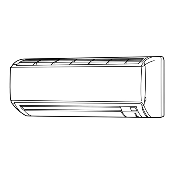
Page 4: Part Names And Functions
PART NAMES AND FUNCTIONS MSZ-HC25VA MSZ-HC35VA MSZ-HC35VAB Air inlet Front panel Air filter (Anti-mold) Air outlet Remote controller Vertical vane Horizontal vane Remote control receiving section Emergency operation switch (E.O. SW) Operation Indicator lamp ACCESSORIES Installation plate Installation plate fi xing screw 4 × 25 mm... -
Page 5: Specification
SPECIFICATION Indoor model MSZ-HC25VA MSZ-HC35VA MSZ-HC35VAB Function Cooling Heating Cooling Heating Cooling Heating Power supply Single phase, 230 V, 50 Hz Running current 1 0.22 Electrical data Power input 1 Model RC4V18-BA or CA RC0J40-ED Fan motor Current 1 0.22 Dimensions W ×... -
Page 6: Noise Criteria Curves
NOISE CRITERIA CURVES MSZ-HC25VA MSZ-HC35VA MSZ-HC35VAB FAN SPEED FUNCTION SPL(dB(A)) LINE FAN SPEED FUNCTION SPL(dB(A)) LINE COOLING COOLING Super High Super High HEATING HEATING NC-70 NC-70 NC-60 NC-60 NC-50 NC-50 NC-40 NC-40 NC-30 NC-30 APPROXIMATE APPROXIMATE THRESHOLD OF THRESHOLD OF... -
Page 7: Outlines And Dimensions
OUTLINES AND DIMENSIONS MSZ-HC25VA MSZ-HC35VA MSZ-HC35VAB Unit : mm 11 × 20 Oblong hole 11 × 26 Oblong hole Installation plate Indoor unit Air in Wall hole ø65 Installation plate Piping Drain hose Air out Insulation ø35 O.D Liquid line ø6.35 - 0.5 m (Flared connection ø6.35) - Page 8 MSZ-HC35VA- MSZ-HC35VAB- MSZ-HC35VA- MSZ-HC35VAB-...
-
Page 9: Refrigerant System Diagram
REFRIGERANT SYSTEM DIAGRAM MSZ-HC25VA MSZ-HC35VA- MSZ-HC35VAB- Unit : mm Refrigerant pipe ø9.52 (with heat insulator) Indoor coil Indoor thermistor heat RT12 exchanger Flared connection Room temperature thermistor RT11 Flared connection Refrigerant pipe ø6.35 (with heat insulator) Refrigerant flow in cooling... -
Page 10: Service Functions
SERVICE FUNCTIONS MSZ-HC25VA MSZ-HC35VA MSZ-HC35VAB 8-1. TIMER SHORT MODE For service, set time can be shortened by short circuit of JPG and JPS on the electronic control P.C. board. The time will be shortened as follows. (Refer to 10-7.) Set time : 1-minute → 1-second Set time : 3-minute →... - Page 11 8-3. AUTO RESTART FUNCTION When the indoor unit is controlled with the remote controller, the operation mode, the set temperature, and the fan speed are memorized by the indoor electronic control P.C. board. “AUTO RESTART FUNCTION” automatically starts operation in the same mode just before the shutoff of the main power. Operation If the main power has been cut, the operation settings remain.
-
Page 12: Microprocessor Control
MICROPROCESSOR CONTROL MSZ-HC25VA MSZ-HC35VA MSZ-HC35VAB WIRELESS REMOTE CONTROLLER Signal transmitting section Operation display section ON/OFF (operate/stop) button Temperature buttons Fan speed control button ECONO COOL button Vane control button Operation select button Timer mode select button Time set buttons RESET button NOTE : Last setting will be stored after the unit is turned OFF with the remote controller. - Page 13 9-1. COOL ( ) OPERATION (1) Press OPERATE/STOP (ON/OFF) button. OPERATION INDICATOR lamp of the indoor unit turns on with a beep tone. (2) Select COOL mode with OPERATION SELECT button. (3) Press TEMPERATURE buttons (TOO WARM or TOO COOL button) to select the desired temperature. The setting range is 16 ~ 31°C.
- Page 14 9-4. AUTO VANE OPERATION 1. Horizontal vane (1) Vane motor drive These models are equipped with a stepping motor for the horizontal vane. The rotating direction, speed, and angle of the motor are controlled by pulse signals (approx. 12 V) transmitted from indoor microprocessor. (2) The horizontal vane angle and mode change as follows by pressing VANE CONTROL button.
- Page 15 (9) To change the airfl ow direction not to blow directly onto your body. When to use this To change the airfl ow COOL/DRY HEAT direction function? Pressing and holding Use this function if The air conditioner starts the cool- The air conditioner starts heating VANE CONTROL button you don’t want the air...
- Page 16 9-5. TIMER OPERATION (ON/OFF TIMER) 1. How to set the timer (1) Press OPERATE/STOP (ON/OFF) button to start the air conditioner. (2) Select the timer mode by pressing the button during operation. Each time this button is pressed, the timer mode is changed in sequence: (OFF TIMER) →...
-
Page 17: Troubleshooting
TROUBLESHOOTING MSZ-HC25VA MSZ-HC35VA MSZ-HC35VAB 10-1. CAUTIONS ON TROUBLESHOOTING 1. Before troubleshooting, check the following: 1) Check the power supply voltage. 2) Check the indoor/outdoor connecting wire for miswiring. 2. Take care of the following during servicing 1) Before servicing the air conditioner, be sure to turn OFF the main unit first with the remote controller, and then after confirming the horizontal vane is closed, turn OFF the breaker and/or disconnect the power plug. -
Page 18: Failure Mode Recall Function
10-2. FAILURE MODE RECALL FUNCTION Outline of the function This air conditioner can memorize the abnormal condition which has occurred once. Even though LED indication listed on the troubleshooting check table (10-4.) disappears, the memorized failure details can be recalled. This mode is very useful when the unit needs to be repaired for the abnormality which doesn't recur. - Page 19 2. Indoor unit failure mode table Upper lamp of OP- Abnormal point ERATION INDICA- Condition Correspondence (Failure mode) TOR lamp Not lighted Normal — — The room temperature thermistor short or 1-time fl ash every Room temperature Refer to the characteristics of the room temperature open circuit is detected every 8 seconds dur- 0.5-second thermistor...
- Page 20 10-3. INSTRUCTION OF TROUBLESHOOTING Start Indoor unit operates. Indoor unit oper- Indoor unit OPERATION INDICATOR Outdoor unit doesn't ates. doesn't receive lamp on the indoor unit is operate normally. the signal from Outdoor unit fl ashing on and off. doesn't operate. remote controller.
-
Page 21: Troubleshooting Check Table
10-4. TROUBLESHOOTING CHECK TABLE Before taking measures, make sure that the symptom reappears for accurate troubleshooting. When the indoor unit has started operation and detected an abnormality of the following condition (the first detection after the power ON), the indoor fan motor turns OFF and OPERATION INDICATOR lamp flashes. OPERATION INDICATOR Lighted Blinking... -
Page 22: A Check Of Indoor Fan Motor
10-5. TROUBLE CRITERION OF MAIN PARTS MSZ-HC25VA MSZ-HC35VA MSZ-HC35VAB Part name Check method and criterion Figure Measure the resistance with a tester. Room temperature thermistor (RT11) Refer to 10-7. "Test point diagram and voltage", "2. Indoor electronic control Indoor coil thermistor P.C. - Page 23 MSZ-HC35VA MSZ-HC35VAB The indoor fan motor error has occurred, and the indoor fan doesn't operate. Turn OFF the power supply. Pay careful attention to the high voltage on the fan motor connector CN211. Turn ON the power supply, wait 5 seconds or more, and then press EMERGENCY OPERATION switch.
- Page 24 B Check of remote controller and indoor electronic control P.C. board Check if the remote controller is exclusive for this air conditioner. Press OPERATE/STOP (ON/OFF) button on the remote controller. Is LCD display on the remote controller Replace the batteries. (Refer to 10-1.4.) visible? (Not clear) Remove the batteries, then set them back...
- Page 25 C Check of indoor P.C. board and indoor fan motor Turn OFF the power supply. Remove indoor fan motor connector CN211 from indoor power P.C. board and vane Measure the resistance of indoor fan Short circuit : motor connector CN151 from the indoor motor.
- Page 26 D How to check miswiring and serial signal error Turn OFF the power supply. Is there rated voltage in the Check the power supply. power supply? Turn ON the power supply. Is there rated voltage between outdoor terminal block S1 and Check the wiring.
- Page 27 E Electromagnetic noise enters into TV sets or radios Is the unit earthed? Earth the unit. Is the distance between the antennas Extend the distance between the antennas and and the indoor unit within 3 m, or is the the indoor unit, and/or the antennas and the distance between the antennas and the outdoor unit.
- Page 28 10-7. TEST POINT DIAGRAM AND VOLTAGE 1. Indoor power P.C. board, Indoor terminal P.C. board MSZ-HC25VA Indoor terminal P.C. board Indoor power P.C. board Varistor (NR11) Resistor (R111) Fuse (F11)( ) Indoor fan motor (CN211) Terminal 230V AC block Connector to indoor electronic...
-
Page 29: Disassembly Instructions
Pull the terminal while pull out the terminal pushing the locking slowly. Locking lever lever. Connector MSZ-HC25VA MSZ-HC35VA MSZ-HC35VAB OPERATING PROCEDURE PHOTOS Photo 1 1. Removing the panel (1) Remove the screw caps of the panel. Remove the screws. (2) Hold the lower ends part of the panel and pull it slightly toward you, and then remove the panel by pushing it upward. - Page 30 OPERATING PROCEDURE PHOTOS Electrical box 2. Removing the indoor electronic control P.C. Photo 2 board and the room temperature thermistor Screw of the (1) Turn the breaker OFF. electrical cover (2) Remove the panel (refer to 1.) and the corner box. (3) Open the indoor electronic control P.C.
- Page 31 OPERATING PROCEDURE PHOTOS 4. Removing the vane motor Photo 4 (1) Turn the breaker OFF. Screws of the vane motor (2) Remove the panel (refer to 1.) and the corner box. (3) Remove the indoor electronic control P.C. board hold- er (refer to 2.).
- Page 32 HEAD OFFICE: TOKYO BLDG., 2-7-3, MARUNOUCHI, CHIYODA-KU, TOKYO 100-8310, JAPAN Copyright 2007 MITSUBISHI ELECTRIC ENGINEERING CO.,LTD Distributed in Aug. 2008. No. OBH466 REVISED EDITION-B 6 Distributed in Feb. 2007. No. OBH466 REVISED EDITION-A 6 New publication, effective Aug. 2008 Distributed in Jan. 2007. No. OBH466 6 Specifications subject to change without notice.