Table of Contents
Advertisement
Parrilla a Gas de 2 Quemadores
OWNER'S MANUAL / MANUAL DEL PROPIETARIO
GUARDE ESTE MANUAL PARA REFERENCIA FUTURA
NOTICE TO INSTALLER:
LEAVE THESE INSTRUCTIONS
WITH THE GRILL OWNER FOR
FUTURE REFERENCE .
AVISO PARA EL
INSTALADOR:
ENTREGUE ESTAS
INSTRUCCIONES AL
PROPIETARIO DE LA PARRILLA
PARA REFERENCIA FUTURA.
2 Burner Gas Grill
ASSEMBLY AND OPERATING IN STRUC TIONS
INSTRUCCIONES DE ARMADO Y OPERACIÓN
SAVE THIS MANUAL FOR FUTURE REFERENCE
HAZARDOUS EXPLOSION MAY RESULT IF THESE WARNINGS AND INSTRUCTIONS
ARE IGNORED. READ AND FOLLOW ALL WARNINGS AND INSTRUCTIONS IN THIS
SE PUEDE PRODUCIR UNA EXPLOSIÓN PELIGROSA SI SE HACE CASO OMISO A
ESTAS ADVERTENCIAS E INSTRUCCIONES. LEA Y SIGA TODAS LAS ADVERTENCIAS
E INSTRUCCIONES EN ESTE MANUAL PARA EVITAR LESIONES PERSONALES,
WARNING/ADVERTENCIA
MANUAL TO AVOID PERSONAL INJURY, INCLUDING DEATH OR
PROPERTY DAMAGE.
INCLUSO LA MUERTE, O LOS DA—OS MATERIALES.
Advertisement
Table of Contents

Related Manuals for Brinkmann 4220


Summary of Contents for Brinkmann 4220
- Page 1 2 Burner Gas Grill Parrilla a Gas de 2 Quemadores OWNER’S MANUAL / MANUAL DEL PROPIETARIO ASSEMBLY AND OPERATING IN STRUC TIONS INSTRUCCIONES DE ARMADO Y OPERACIÓN SAVE THIS MANUAL FOR FUTURE REFERENCE GUARDE ESTE MANUAL PARA REFERENCIA FUTURA WARNING/ADVERTENCIA NOTICE TO INSTALLER: HAZARDOUS EXPLOSION MAY RESULT IF THESE WARNINGS AND INSTRUCTIONS LEAVE THESE INSTRUCTIONS...
- Page 2 IMPORTANT SAFETY WARNINGS WE WANT YOU TO ASSEMBLE AND USE YOUR GRILL AS SAFELY AS POSSIBLE. THE PURPOSE OF THIS SAFETY ALERT SYMBOL IS TO ATTRACT YOUR ATTENTION TO POSSIBLE HAZARDS AS YOU ASSEMBLE AND USE YOUR GRILL. WHEN YOU SEE THE SAFETY ALERT SYMBOL PAY CLOSE ATTENTION TO THE INFORMATION WHICH FOLLOWS! READ ALL SAFETY WARNINGS AND INSTRUCTIONS CAREFULLY BEFORE ASSEMBLING AND OPERATING YOUR GRILL.
-
Page 3: Table Of Contents
TABLE OF CONTENTS General Warnings ..........3 Installation and LP Cylinder Specifi cations and Safe Use . -
Page 4: General Warnings
GENERAL WARNINGS WARNING • Never use natural gas in a unit designed for liquid propane gas. • Never use charcoal or wood briquets in a gas grill. Flavoring chips must be contained in a metal smoking box to contain ash and prevent fires. •... -
Page 5: Installation And Lp Cylinder Specifi Cations And Safe Use
WARNING • FOR OUTDOOR USE ONLY. DO NOT operate indoors or in an enclosed area such as a garage, shed or breezeway. • Use your grill OUTDOORS in a well ventilated space away from dwellings or other buildings to prevent dangers associated with gas accumulation and toxic vapors. Although minimum clearance is 36 inches (91 cm), we strongly recommend that you do not operate this appliance within 10 ft. - Page 6 CYLINDER SPECIFICATIONS: When purchasing or exchanging a cylinder for your gas grill, it must be constructed and marked in accordance with the specifications for LP gas cylinders of the U.S. Department of Transportation (DOT) or the National Standard of Canada, CAN/CSA-B339 Cylinders, Spheres and Tubes for Transportation of Dangerous Goods;...
-
Page 7: Connecting Lp Cylinder And Hose / Regulator To Grill
WARNING FILLING THE LP GAS CYLINDER: • Allow only qualified LP gas dealers to properly fill or repair your LP gas cylinder. • New tanks should be purged prior to filling; inform LP gas dealer if you are using a new tank. •... -
Page 8: Connecting Hose And Regulator To An Lp Gas Cylinder
• DO NOT use any other pressure regulator/hose assembly other than the one supplied with your grill. Replacement pressure regulator/hose assembly must be part No 155-4220-S, which can be obtained by contacting customer service at 800-527-0717. •... -
Page 9: Leak Testing
DANGER LEAK TESTING: To prevent fire or explosion hazard: • DO NOT smoke or permit ignition sources in the area while conducting a leak test. • Perform test OUTDOORS only in a well ventilated area. • Never perform a leak test with a match or open flame. •... -
Page 10: Pre-Start Check List
Inspect the gas supply hose for burns, chaffing, kinks, and proper routing before each use. If it is evident there is excessive abrasion or wear, or the hose is cut, it must be replaced prior the grill being used. Replace with hose and regulator, Model No. 155-4220-S, which can be obtained by contacting customer service at 800-527-0717. -
Page 11: Connecting Lp Cylinder And Hose / Regulator To Grill
WARNING Read, understand and follow all warnings and instructions contained in this manual. DO NOT skip any of the warnings and instructions contained in the preceding sections of this manual. WARNING LIGHTING INSTRUCTIONS: Follow the instructions exactly. 1. OPEN THE GRILL LID before attempting to light a burner so that fumes do not accumulate inside the grill. - Page 12 Note: Observe flame height when lit: Flame should be a Blue/Yellow color between 1”–2” when burner is on “HIGH”. TURNING OFF THE GRILL: 1. Turn off the cylinder valve. 2. Turn both burner control knobs to the “OFF” position. Note: Turn off LP cylinder first to prevent gas from being left in the system under pressure.
-
Page 13: Operating Grill And Helpful Hints
WARNING OPERATING THE GRILL: Never use Charcoal or Lighter Fluid inside your Gas Grill. Read and follow all warnings and instructions contained in the preceding sections of this manual. BREAKING IN YOUR GRILL: • In manufacturing and preserving the components of your grill, oil residue may be present on the burner and cooking surfaces of your grill. -
Page 14: Proper Care And Maintenance
GRILL COOKING TIPS CLEANLINESS • Always wash hands thoroughly with soap and hot water prior to handling food and after handling raw meat, uncooked poultry or seafood. • When using a platter to carry raw meat, uncooked poultry or seafood to the grill, make sure to wash the platter thoroughly with soap and hot water before placing cooked foods back on the platter or use different platters for raw and cooked foods. -
Page 15: Cleaning And Maintenance
CLEANING AND MAINTENANCE: • Keep the appliance free and clear of combustible materials, gasoline and other flammable vapors and liquids. • Keep the ventilation openings of the cylinder enclosure free and clear of debris. • Visually check burner flames for proper operation (see pictorial in “Burner Assembly/Maintenance” under Proper Care and Maintenance). -
Page 16: Transporting And Storage
BURNER ASSEMBLY/MAINTENANCE CONTINUED Note: Follow the “Gas Leak Testing” section of this manual. Relight burners to verify proper operation. 12. Replace heat distribution plates and cooking grills. PROPER BURNER OPERATION COOKING GRILLS • Clean with mild soap detergent and water. A brass bristled brush or a nylon cleaning pad can be used to remove residue from the stainless steel surfaces. -
Page 17: Trouble Shooting
BEFORE STORING YOUR GRILL: • Ensure that the cylinder valve is fully closed. • Clean all surfaces. • Lightly coat the burners with cooking oil to prevent excess rusting. • If storing the grill indoors, disconnect the LP tank and leave the LP tank OUTDOORS. •... -
Page 18: Frequently Asked Questions
FREQUENTLY ASKED QUESTIONS These questions and answers are for your general knowledge, and may not be applicable to your model grill. Your grill’s serial number and model number, and the contact information for Brinkmann Customer Service, are listed on a silver label found beneath the control panel, on the back of the grill or on the side of the grill body, under the side shelf. - Page 19 FREQUENTLY ASKED QUESTIONS Cleaning Stainless Steel Cooking Grills: Wash grills with a mild detergent and rinse with hot water before initial use and as needed. DO NOT use a commercial oven cleaner. For stubborn food residue, use a degreaser and fiber or brass cleaning brush. Cleaning Porcelain-Finished Cast-Iron Cooking Grills: Wash grills with a mild detergent and rinse with hot water before initial use and as needed.
-
Page 20: Parts List And Assembly Instructions
PARTS BAG CONTENTS Make sure you have all items listed under PARTS LIST and PARTS CARD CONTENTS before you begin the installation process. PARTS CARD CONTAINS: Qty. M6 X 12 Bolts (Black) M4 X 10 mm Bolt (Silver) M4 Washer M4 Nut Wheel Washers M6 X 12 mm Bolts (Black) -
Page 21: Assembly Instructions
ASSEMBLY INSTRUCTIONS READ ALL SAFETY WARNINGS & ASSEMBLY INSTRUCTIONS CAREFULLY BEFORE ASSEMBLING OR OPERATING YOUR GRILL. WE RECOMMEND TWO PEOPLE WORK TOGETHER WHEN AS SEM BLING THIS UNIT. ® The following provided tools are required to assemble this Brinkmann 2 Burner Gas Grill: PARTS LIST: Hood &... - Page 22 FOR COVERS, ACCESSORIES AND OTHER PRODUCTS, PLEASE VISIT US ONLINE AT: Inspect contents of the box to ensure all parts are included and undamaged.
- Page 23 Choose a good, cleared assembly area and get a friend to help you put your grill together. Lay card- board down to protect grill finish Open and assembly area. CAUTION: Some parts may contain sharp edges. Wear protective gloves if necessary. Step 1 Place cart assembly upright.
- Page 24 Note: With the help of a friend, Left Front Leg Cap turn the hood and firebox assembled over. Try to Left Rear Leg Cap minimize the stress to the legs. Left Front Leg Step 3 Install left rear leg cap onto left rear cart leg.
- Page 25 Note: With the help of a friend, Wing Nut turn the cart to its upright Tank Retention position. Support Bracket Tank Retention Bracket Step 6 Carriage Bolt Unscrew the pre-attached bolts from the tank retention bracket. Attach tank retention bracket in Bolts between right front and rear cart legs using the two pre-attached...
- Page 26 Step 8 Unscrew the pre-attached M6 Left Side Table bolts, attach the left side table Assembly assembly to the left side of grill body. Place table over bolts and slide down to lock into place, then tighten bolts securely. Figure 1 Figure 2 Step 9 Unscrew the pre-attached M6...
- Page 27 Step 10 Side Burner To install the side burner, remove the pre-attached wing nut and washer on the side burner and install the side burner as illustrated. Step 11 Position burner venturi over side burner valve nozzle as illustrated. Valve Nozzle Burner Venturi M4 X 10 mm Bolt...
- Page 28 Step 14 Attach side burner igniter lead wire to electrode as illustrated. Electrode Side Burner Igniter Lead Wire Step 15 Place side burner grate on the side burner. Side Burner Grate Step 16 Insert grease cup into the grease tray. Make sure to slide cup onto tracks as illustrated.
- Page 29 Warming Rack Step 17 Place the heat distribution plates on lower level of grill body assembly, in space on brackets, Cooking Grate directly above burners. Step 18 Insert warming rack through holes Heat Distribution in grill lid and then insert the Plates warming rack legs into the holes in grill body.
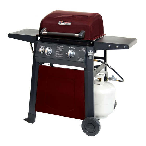
- Page 30 ® Brinkmann 4220 (Assembled)
- Page 31 LA LIMITACIÓN O EXCLUSIÓN ANTERIOR PODRÍA NO SER APLICABLE EN SU CASO. ESTA GARANTÍA LE OTORGA DERECHOS LEGALES ESPECÍFICOS Y USTED PUEDE TENER ADEMÁS OTROS DERECHOS QUE VARÍAN DE UN ESTADO A OTRO. ©2012 The Brinkmann Corporation 140-4220-S Owner’s Manual for Model: 0812 Manual del Propietario para el Modelo: Dallas, Texas 75244 U.S.A.