
Related Manuals for Toro 74629


Summary of Contents for Toro 74629
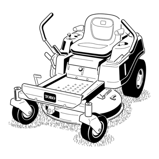
- Page 1 Form No. 3381-516 Rev A TimeCutter ® SS 3216 Riding Mower Model No. 74629—Serial No. 314000001 and Up *3381-516* A Register at www.Toro.com. Original Instructions (EN)
-
Page 2: Introduction
Important: This engine is not equipped with a spark arrester muffler. It is a violation of California Public You may contact Toro directly at www.Toro.com for product Resource Code Section 4442 to use or operate the engine and accessory information, help finding a dealer, or to register on any forest-covered, brush-covered, or grass-covered your product. -
Page 3: Table Of Contents
Cleaning and Storage ..........41 Troubleshooting ............42 Introduction ..............2 Schematics ..............44 Safety ................4 Safe Operating Practices........... 4 Toro Riding Mower Safety ........6 Slope Indicator ............7 Safety and Instructional Decals ......... 8 Product Overview ............11 Controls ...............11 Operation ..............12 Adding Fuel............12... -
Page 4: Safety
In these instances, others from serious injury. Toro has refined the statement to convey the meaning of the • Always follow the recommendations for any application standard while better matching the product this Operator's of counterweights. - Page 5 Towing Safety • Do not mow slopes when grass is wet. Slippery conditions reduce traction and could cause sliding and • Do not attach towed equipment except at the hitch point. loss of control. • Follow the attachment manufacturer's recommendation •...
-
Page 6: Toro Riding Mower Safety
Never interfere with the intended function of a safety device or to reduce the protection provided by a safety The following list contains safety information specific to Toro device. Check their proper operation regularly. products or other safety information that you must know that •... -
Page 7: Slope Indicator
Slope Indicator G011841 Figure 3 This page may be copied for personal use. 1. The maximum slope you can safely operate the machine on is 15 degrees. Use the slope chart to determine the degree of slope of hills before operating. Do not operate this machine on a slope greater than 15 degrees. Fold along the appropriate line to match the recommended slope. -
Page 8: Safety And Instructional Decals
Safety and Instructional Decals Safety decals and instructions are easily visible to the operator and are located near any area of potential danger. Replace any decal that is damaged or lost. 93-7009 Manufacturer's Mark 1. Warning—don't operate the mower with the deflector up or 1. - Page 9 Battery Symbols Some or all of these symbols are on your battery 1. Explosion hazard 6. Keep bystanders a safe distance from the battery. 2. No fire, open flame, or 7. Wear eye protection; smoking. explosive gases can cause blindness and other injuries 3.
- Page 10 120-2239 1. Warning—read the Operator's Manual. 5. Warning—do not use split ramps, use a full ramps when transporting machine. 2. Warning—read the instructions before servicing or performing 6. Loss of traction/control hazard, slopes—loss of traction/control maintenance; move the motion control levers to the park on a slope, disengage the blade control switch (PTO), (brake) position, remove the ignition key and disconnect the proceed off the slope slowly.
-
Page 11: Product Overview
Ignition Switch Product Overview The ignition switch has 3 positions: Off, Run, and Start. The key will turn to Start and move back to Run upon release. Turning the key to the Off position will stop the engine; however, always remove the key when leaving the machine to prevent someone from accidentally starting the engine (Figure 5). -
Page 12: Operation
Fuel-presence Window Operation The fuel window located on the left-hand side of the machine, Note: Determine the left and right sides of the machine can be used to verify the presence of gasoline in the tank from the normal operating position. (Figure 7). -
Page 13: Filling The Fuel Tank
of varnish deposits in the fuel system, use fuel stabilizer DANGER at all times. In certain conditions during fueling, static electricity can be released causing a spark which Filling the Fuel Tank can ignite the gasoline vapors. A fire or explosion Ensure that the engine is shut off and the motion controls are from gasoline can burn you and others and can in the parked position. -
Page 14: Checking The Engine-Oil Level
3. Install the fuel-tank cap securely, and tighten until it clicks. Checking the Engine-oil Level Before you start the engine and use the machine, check the oil level in the engine crankcase; refer to Checking the Engine-oil Level (page 25). Breaking in a New Machine New engines take time to develop full power. -
Page 15: Starting The Engine
Understanding the Safety-interlock System WARNING If safety-interlock switches are disconnected or damaged, the machine could operate unexpectedly causing personal injury. • Do not tamper with the interlock switches. • Check the operation of the interlock switches daily, and replace any damaged switches before operating the machine. -
Page 16: Operating The Blades
Figure 15 1. Control panel 2. Blade-control switch—On position Figure 14 Disengaging the Blades 1. Control panel 4. Off 2. Ignition key—run position 5. Run Push down on the blade-control switch to move it to the Off position, and disengage the blades (Figure 16). 3. -
Page 17: Stopping The Engine
6. Repeat with the other motion-control lever. 7. While sitting on the seat, move the blade-control switch to Off, and lock the motion-control levers in the park position. 8. Start the engine. 9. While the engine is running, engage the blade-control switch, and rise slightly from the seat. -
Page 18: Driving Forward
Using the Smart Speed™ Control Driving Forward System 1. Move the levers to the center, unlocked position. The Smart Speed™ Control-System lever, located below the 2. To go forward, slowly push the motion-control levers operating position (Figure 18), gives the operator a choice to forward (Figure 17). -
Page 19: Stopping The Machine
Driving Backward 1. Move the levers to the center, unlocked position. 2. To go backward, look behind you and down, as you slowly pull the motion-control levers rearward (Figure 20). G014476 Figure 21 1. Height-of-cut lever 3. 115 mm (4.5 inches)—transport position G008953... -
Page 20: Adjusting The Motion-Control Levers
Adjusting the Motion-control Adjusting the Tilt Levers The motion-control levers can be tilted fore or aft for maximum operator comfort. 1. Loosen the upper bolt holding the control lever to the Adjusting the Height control-arm shaft. The motion-control levers can be adjusted higher or lower for 2. -
Page 21: Operating The Machine
g017303 Figure 24 1. Bypass-lever locations 3. Lever position for pushing the machine 2. Lever position for operating the machine 6. When finished, ensure that the key has been returned to the Stop position to avoid draining the battery charge. Note: If the machine fails to move, the electric brake may still be engaged. -
Page 22: Operating Tips
If a blade is damaged or worn, replace it immediately with a genuine Toro replacement blade. Cutting 1/3 of the Grass Blade It is best to cut only about 1/3 of the grass blade. Cutting more than that is not recommended unless grass is sparse, or it is late fall when grass grows more slowly. -
Page 23: Maintenance
Maintenance Note: Determine the left and right sides of the machine from the normal operating position. Recommended Maintenance Schedule(s) Maintenance Service Maintenance Procedure Interval • Change the engine oil. After the first 5 hours • Check the safety-interlock system. • Clean and check the air cleaner foam element. •... -
Page 24: Lubrication
Lubrication Engine Maintenance Greasing the Bearings Servicing the Air Cleaner Service Interval: Every 25 hours—Grease all the lubrication Service Interval: Before each use or daily—Clean and check points. the air cleaner foam element. Grease Type: No. 2 General Purpose, Lithium-Base Grease Every 50 hours—Replace the air cleaner paper 1. -
Page 25: Servicing The Engine Oil
Servicing the Engine Oil Oil Type: Detergent oil (API service SF, SG, SH, SJ, or higher) Crankcase Capacity: 1.0 L (34 oz) when you do not change the filter; 1.05 L (36 oz) when you change the filter. Viscosity: See the table below. Figure 28 1. -
Page 26: Changing The Engine Oil
Important: Do not overfill the crankcase with oil 11. Change the engine-oil filter; refer to Changing the and run the engine; engine damage may result. Engine-oil Filter (page 26). 12. Slowly pour approximately 80% of the specified Changing the Engine Oil amount of oil into the fill hole (Figure 31). -
Page 27: Servicing The Spark Plug
Servicing the Spark Plug Checking the Spark Plug 1. Inspect the spark plug (Figure 34). Service Interval: Every 50 hours—Check the spark plug. Note: If you see light brown or gray on the insulator, Every 100 hours—Replace the spark plug. the engine is operating properly. -
Page 28: Fuel System Maintenance
Fuel System 5. Remove the filter from the fuel lines. 6. Install a new filter with the flow direction arrow coming Maintenance from the fuel tank and pointing to the engine. Note: Move the hose clamps close to the filter (Figure DANGER 35) to secure it in place. -
Page 29: Electrical System Maintenance
Electrical System WARNING Maintenance Incorrect battery-cable routing could damage the machine and cables causing sparks. Sparks can cause the battery gasses to WARNING explode, resulting in personal injury. • Always disconnect the negative (black) CALIFORNIA battery cable before disconnecting the Proposition 65 Warning positive (red) cable. -
Page 30: Servicing The Fuses
Charging the Battery Servicing the Fuses Service Interval: Before storage—Charge the battery and The electrical system is protected by fuses. It requires disconnect battery cables. no maintenance; however, if a fuse blows, check the component/circuit for a malfunction or short. 1. -
Page 31: Drive System Maintenance
Releasing the Electric Brake Drive System Maintenance The electric brake releases by manually rotating the link arms forward. Once the electric brake is energized the brake will reset. Checking the Tire Pressure To release the brake: 1. Locate the shaft on the electric brake where the Service Interval: Every 25 hours—Check tire pressure. -
Page 32: Cooling System Maintenance
If a blade is damaged or worn, replace at all times. it immediately with a genuine Toro replacement blade. For Use a dry brush to clean grass and accumulated debris from convenient sharpening and replacement, you may want to the air-intake screen and around the engine. -
Page 33: Inspecting The Blades
Inspecting the Blades 3. Measure from the tip of the blade to the flat surface (Figure 43). Service Interval: Before each use or daily—Check the cutting blades. 1. Inspect the cutting edges (Figure 41). Note: If the edges are not sharp or have nicks, remove and sharpen the blades;... -
Page 34: Removing The Blades
(Figure 48). optimum performance and continued safety conformance Note: If the blade stays in a horizontal position, the of the machine, use genuine Toro replacement blades. blade is balanced, and can be used. Replacement blades made by other manufacturers may result in non-conformance with safety standards. -
Page 35: Leveling The Mower Deck
2. Install the blade stiffener, the curved washer (cupped within 5 mm (3/16 inch), an adjustment is required; side toward the blade), and the blade bolt (Figure 46). continue with this procedure. 3. Torque the blade bolt to 47 to 88 N-m (35 to 65 ft-lb). 6. -
Page 36: Adjusting The Front-To-Rear Blade Slope
Adjusting the Front-to-Rear Blade Slope Check the front-to-rear blade slope any time you install the mower. If the front of the mower is more than 7.9 mm (5/16 inch) lower than the rear of the mower, adjust the blade level using the following instructions: 1. -
Page 37: Removing The Mower
G014634 Figure 54 1. Adjusting rod 3. Locknut 2. Adjusting block G014635 Figure 55 7. To raise the front of the mower, tighten the adjustment nut. 1. Front support rod 3. Deck bracket 2. Locking nut 8. To lower the front of the mower, loosen the adjustment nut. -
Page 38: Installing The Mower
Installing the Mower 2. Remove the nut (3/8 inch) from the rod under the mower (Figure 57). 1. Park the machine on a level surface and disengage the 3. Slide the rod out of the short stand-off, spring, and blade-control switch. grass deflector (Figure 57). -
Page 39: Mower Belt Maintenance
(Figure 58). remove the idler spring from the deck hook to remove 6. Using a spring removal tool (Toro part no. 92-5771), tension on the idler pulley, and roll the belt off of the install the idler spring over the deck hook and placing pulleys (Figure 58). -
Page 40: Cleaning
Cleaning 9. Run the mower again for 1 to 3 minutes to remove excess water. Washing the Underside of the WARNING Mower A broken or missing washout fitting could expose you and others to thrown objects or Service Interval: After each use—Clean the mower-deck blade contact. - Page 41 Storage plug(s) removed from the engine, pour two tablespoons of engine oil into the spark plug hole. Use the starter to crank the engine and distribute the oil inside the Cleaning and Storage cylinder. Install the spark plug(s). Do not install the wire on the spark plug(s).
- Page 42 Troubleshooting Problem Possible Cause Corrective Action The engine overheats. 1. The engine load is excessive. 1. Reduce the ground speed. 2. The oil level in the crankcase is low. 2. Add oil to the crankcase. 3. The cooling fins and air passages 3.
- Page 43 Problem Possible Cause Corrective Action The cutting height is uneven. 1. The blade(s) is not sharp. 1. Sharpen the blade(s). 2. A cutting blade(s) is/are bent. 2. Install a new cutting blade(s). 3. The mower is not level. 3. Level the mower from side-to-side and front-to-rear.
- Page 44 Schematics G014644 Electrical Diagram (Rev. A)
- Page 45 Notes:...
- Page 46 Notes:...
- Page 47 Notes:...
- Page 48 Toro importer. If all other remedies fail, you may contact us at Toro Warranty Company. Australian Consumer Law: Australian customers will find details relating to the Australian Consumer Law either inside the box or at your local Toro Dealer.