
Related Manuals for Tokyo Hy-Power HL-45B


Summary of Contents for Tokyo Hy-Power HL-45B
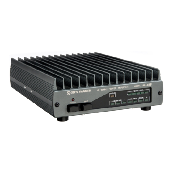
- Page 1 Instruction Manual Solid-State HF/50MHz Band 45W Linear Power Amplifier Model HL-45B TOKYO HY-POWER LABS., INC.
- Page 2 ( 1 ) FEATURES HL-45B is a solid-state HF/50MHz band linear power amplifier with the maximum output power of 45W. Designed RF drive power is 5W. This amplifier is particularly designed for the use with popular portable radio of YAESU FT-817.
- Page 3 ( 2 ) SPECIFICATIONS Frequency : HF Band (1.8 ~ 28MHz and 50MHz Amateur Bands) Mode : SSB(A3E), CW(A1A), FM(F3E) RF Output Power : SSB (PEP)/CW 45W (Typical maximum output) RF Drive Power : 5W max. Duty Cycle 3 minutes (Continuous carrier transmission) DC Power : DC 13.8V, 8.5A max.
-
Page 4: Power Level
( 3 ) FRONT and REAR PANELS <FRONT PANEL> $` POWER : ON/OFF switch for DC power. When it is first pushed, the switch is locked to turn DC power “ ON” . If it is pushed again, the lock will be reset to turn DC power “ OFF” . $a BAND (Manual Band Select Switch) : As you press this button, BAND will be shifted to upper band. - Page 5 Connector to apply RF drive signal from the transceiver. Connect the coaxial jumper cable from the transceiver “ ANT” . Please note that input power for HL-45B is 5W max. $f REMOTE : Socket for remote cable from the transceiver.
- Page 6 ( 4 ) TYPICAL CONNECTION AND SETTING A. <Connec t i ons f or FT- 817 Com bi nat i on> H F / 50M H z B and A ntenna H L -45B C oaxi al C able 50 © S W R M eter or P ow erm eter R em ote C on trol C a b le...
- Page 7 5) When you wish to run the transceiver only and do not need to amplify, simply turn off the POWER of HL-45B. The signal to and from the radio will bypass the amplifier, so you do not need to remove the cables.
- Page 8 ( 6 ) REMOTE (Remote Control Socket) Pin assignment of REMOTE socket is shown in the following table for your convenience. You can connect the supplied control cable for FT-817 to this ACC socket. Or prepare a suitable control cable for your own radio using the supplied 8 pin DIN plug.
- Page 9 ( 7 ) ALC POT ADJUSTMENT If the drive power from the radio exceeds the designed limit of 5W, output of the amplifier will also exceed the designed value of 45W, and output signal wave form may get distorted, especially in SSB mode. In order to keep the output within the maximum limit and to avoid signal distortion, ALC connection is most effective.
- Page 10 3) Do not exceed the RF input limit of 5W. 4) Rated DC power supply voltage is 13.8V. Higher voltage will give stress to the expensive RF power MOS FETs. Never apply AC100V, DC24V, etc. or HL-45B will be seriously damaged at once.
- Page 11 DC power supply shows an unstable behavior as you key the radio and HL-45B amp, insert ferrite cores or clip both ends of DC power cable with clip-on ferrite cores. (For further details, consult with your local radio dealer or manufacturers of respective equipments.)