Advertisement
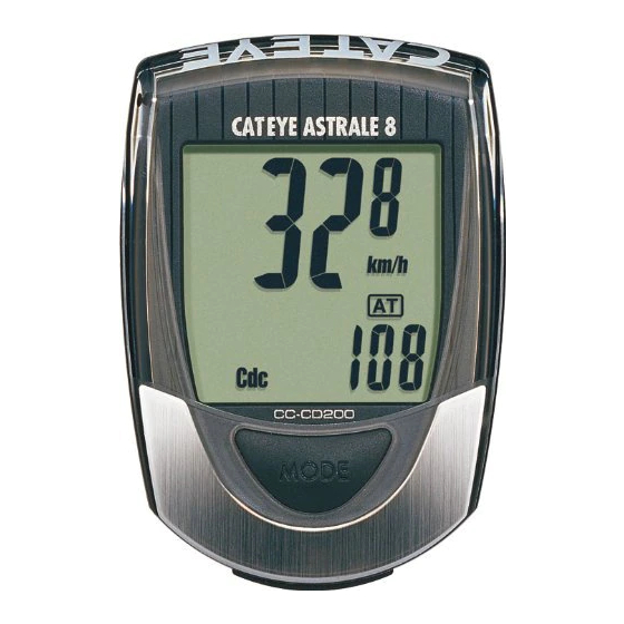
CAT EYE ASTRALE 8
CYCLOCOMPUTER CC-CD200
®
E: Owner's Manual
ASTRALE8
U.S. Pat. Nos.4633216/4642606/5226340/5236759 Pat. and Design Pat. Pending
Please read these instructions carefully before installing or
using the CAT EYE ASTRALE 8.
Please don't throw away this manual, Keep the manual at a place easily accessible.
Installation of the Computer on Your Bike
The computer comeswith the following parts.
3
2
1
4
9
5
8
7
1 Bracket
5 Sensor Rubber Pad
2 Cord
6 Wheel Magnet
3 Speed Sensor
7 Cadence Magnet
8 Bracket Rubber Pad
(short cord)
4 Cadence Sensor
9 Nylon Ties (12)
(long cord)
1
Mount the wheel magnet and speed sensor
• Mount the wheel magnet 6 on a spoke of the front wheel so the surface of the magnet
will face the sensor.
• Secure the speed sensor 3 on the front fork with the larger nylon ties 9.
6
Sensor Side
Spoke
2
Mount the cadence magnet and cadence sensor.
• Mount the cadence magnet 7 on the crank arm so that it faces the sensor.
• Secure the cadence sensor 4 on the left chain stay with the nylon ties 9.
9
Inward Side of
Sensor Side
The Crank Arm
7
Important Note
Mount the magnets 6 (7) and the sensors 3 (4) on the appropriate positions so that
the center of each magnet 6 (7) may align with the the marked line on the sensor
when the front wheel (or the crank arm) is rotated.
3
6
Center
Important Note
Adjust the position of each sensor so they are within 5mm of the 6 (7) magnet.
Secure the nylon ties.
Front Fork
6
3
Rotate
Within 5 mm
Copyright © 2002 CAT EYE Co. Ltd.
CCMCD2-021210 066600250 1
3
6
1
Front Fork
3
9
4
7
Marked Line
4
Marked Line
7
Center
Left Chain Stay
7
4
Crank Pedal
Rotate
Within 5 mm
• Pay attention to the road or trail! Do not be distracted by the
• Be sure to securely mount the magnet, the sensor, and the
Warning
• Keep batteries out of reach of small children. Dispose of batter-
• Avoid unnecessary prolonged exposure to the sun. Never at-
Important
• Don't use thinner, benzene or alcohol to wipe the surface of the
Note
3
Mount The Bracket
Secure the cord on the frame or the fork with the nylon ties 9 and coil it around the brake
cable to lead to the handle bar.
Put the rubber pad 8 on the bracket 1 and secure the bracket on the handle bar with the
screw. Slide the computer into the bracket until you hear the click sound. The contact
points are automatically closed. When you need to remove the computer, slide forward the
computer with the lever pushed simultaneously.
Allow enough wire clearance in the area marked with
Note
the handlebars all the way from side to side without pulling the wire.
2
4
Basic Functions Test
Spin the front wheel to see if Speed is reading properly. Push the mode button until Cadence
(Cdc) is in the sub-display. Spin the crank arm backwards to test if Cadence is reading
properly.
When the computer does not indicate the speed/cadence, check the position of the
Note
magnet and the sensor.
Rotate the front wheel.
Computer Set-up
(For first use or after replacing the battery)
Left Chain
START/STOP Button
Stay
MODE Button
1
All Clear
Push the AC button on the backside.
* Push the AC button when using this
system for the first time and every
time the battery is replaced.
2
Measurement Selection
Select the measurement unit, kilometer or mile, by pushing the
MODE button. And fix it by pushing the SET button.
Kilometer
SET
3
Set The Tire Circumference
Set the tire circumference in mm.
Refer to the chart shown on the right.
Note
Setting is fixed and completed by pushing the SET button.
SET
(the screen will show the time measurement in this state)
* The auto mode is ON in this state.
computer.
bracket on your bicycle. Periodically check to insure they are
mounted securely and the screws are not loosen.
ies according to local regulations.
tempt to disassemble the computer head.
computer. They may damage the surface of computer.
1
9
8
Rotate the crank arm
OK
!
Contact Point
SET Button
AC Button
AC Button
Mile
MODE
Increase the
number
Max. 2999 mm
MODE
Decrease
the number
Min. 10 mm
ST/STOP
Preparation Complete.
to insure you can turn
Lever
Slide
1
OK
You need to know the
tire circumference
(L mm) beforehand.
You can refer to the
L mm
guide chart to roughly
know the tire circum-
ference.
Tire size
L(mm)
12 x1.75
935
14 x 1.50
1020
14 x 1.75
1055
16 x 1.50
1185
16 x 1.75
1195
18 x 1.50
1340
18 x 1.75
1350
20 x 1.75
1515
20 x 1-3/8
1615
22 x 1-3/8
1770
22 x 1-1/2
1785
24 x 1
1753
24 x 3/4 Tubular
1785
24 x 1-1/8
1795
24 x 1-1/4
1905
24 x 1.75
1890
24 x 2.00
1925
24 x 2.125
1965
26 x 7/8
1920
26 x 1(59)
1913
26 x 1(65)
1952
26 x 1.25
1953
26 x 1-1/8
1970
26 x 1-3/8
2068
26 x 1-1/2
2100
26 x 1.40
2005
26 x 1.50
2010
26 x 1.75
2023
26 x 1.95
2050
26 x 2.00
2055
26 x 2.10
2068
26 x 2.125
2070
26 x 2.35
2083
26 x 3.00
2170
27 x 1
2155
27 x 1-1/8
2161
27 x 1-1/4
2161
27 x 1-3/8
2169
650 x 35A
2090
650 x 38A
2125
650 x 38B
2105
700 x 18C
2070
700 x 19C
2080
700 x 20C
2086
700 x 23C
2096
700 x 25C
2105
700 x 28C
2136
700 x 30C
2170
700 x 32C
2155
700C Tubular
2130
700 x 35C
2168
700 x 38C
2180
700 x 40C
2200
Tire size is usually shown on
the sidewall of tires.
Advertisement

Related Manuals for Cateye Astrale 8


Summary of Contents for Cateye Astrale 8
- Page 1 Please read these instructions carefully before installing or screw. Slide the computer into the bracket until you hear the click sound. The contact using the CAT EYE ASTRALE 8. points are automatically closed. When you need to remove the computer, slide forward the Please don’t throw away this manual, Keep the manual at a place easily accessible.
-
Page 2: Computer Operations
Phone: 303-443-4595 Toll Free: 800-5CATEYE Fax: 303-473-0006 e-mail: service@cateye.com Is the gap between the sensor and the magnet too big? URL: http://www.cateye.com * Accessory parts are available for the customers as shown below. (should be within 5 mm)