
Related Manuals for Toshiba RAS-13SKHP-E


Summary of Contents for Toshiba RAS-13SKHP-E
-
Page 1: Service Manual
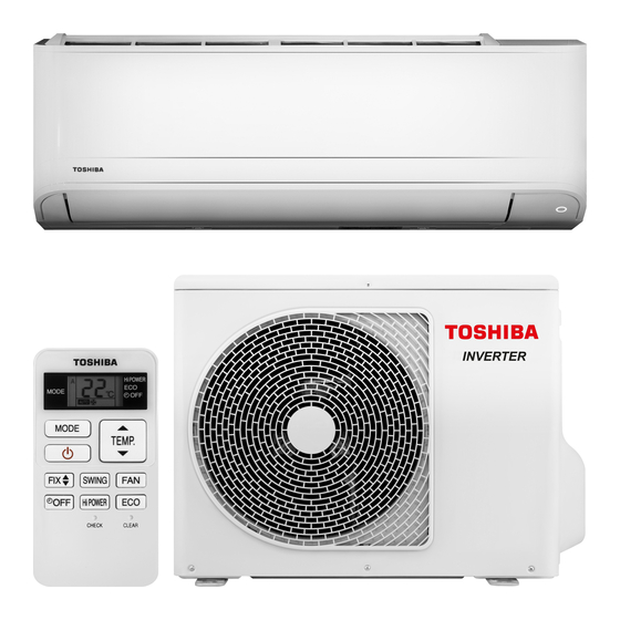
FILE NO. SVM-07033-1 SERVICE MANUAL AIR CONDITIONER SPLIT WALL TYPE RAS-13SKHP-E / RAS-13S2AH-E Revised May, 2007... -
Page 2: Table Of Contents
FILE NO. SVM-07033-1 CONTENTS SPECIFICATIONS CONSTRUCTION VIEWS Indoor Unit Outdoor Unit WIRING DIAGRAM SPECIFICATION OF ELECTRICAL PARTS Indoor Unit Outdoor Unit REFRIGERATION CYCLE DIAGRAM CONTROL BLOCK DIAGRAM OPERATION DESCRIPTION Remote control Description of Operation Circuit Outline of Air Conditioner Circuit Description of Safety and Reliability Prevention Function One-Touch Operation Hi POWER Operation... - Page 3 FILE NO. SVM-07033 INSTALLATION PROCEDURE Safety Cautions Installation Diagram of Indoor and Outdoor Units Installation Indoor Unit Outdoor Unit How to Set Remote Control Selector Switch Others TROUBLESHOOTING CHART Troubleshooting Procedure Basic Check Items Primary Judgement Self-Diagnosis by Remote Control (Check Code) Troubleshooting Flowcharts Troubleshooting for Remote Control (Including the Indoor P.C.
-
Page 4: Specifications
FILE NO. SVM-07033 1. SPECIFICATIONS MODEL RAS-13SKHP-E / RAS-13S2AH-E ITEM Cooling Heating 220 V 240 V 220 V 240 V Capacity 3.55 3.60 3.95 4.05 Phase 1Æ Power source 220 - 240 Power consumption 1.12 1.16 1.08 1.12 Power factor... - Page 5 FILE NO. SVM-07033 Note : 1 · Capacity is based on the following temperature conditions. JIS C9612 Condition Temperature Cooling Heating (DB) 27°C 20°C Indoor unit inlet air temperature (WB) 19°C 15°C (DB) 35°C 7°C Outdoor unit inlet air temperature (WB) 24°C 6°C...
-
Page 6: Construction Views
FILE NO. SVM-07033-1 2. CONSTRUCTION VIEWS 2-1. Indoor Unit Air filter Air inlet Front panel Heat exchanger Knock out system Knock out system Installation plate hanger Wireless remote controller Installation plate hanger Drain hose (0.50m) Connecting pipe (0.35m) Connecting pipe (0.40m) (Flare 12.7mm) (Flare... -
Page 7: Outdoor Unit
FILE NO. SVM-07033 2.2. Outdoor Unit Ø6 hole R5.5 Ø6 hole Ø11x14 hole A detail Drawing (Back leg) Ø 11 x 14 Hole 25 Drain outlet Ø B Detail Drawing (Front leg) (For 8 - 10 anchor bolt) Ø Ø FAN-GUARD Ø... -
Page 8: Wiring Diagram
FILE NO. SVM-07033 3. WIRING DIAGRAM OUTDOOR OUTDOOR OUTDOOR OUTDOOR OUTDOOR OUTDOOR OUTDOOR OUTDOOR OUTDOOR OUTDOOR OUTDOOR OUTDOOR TERMINAL TERMINAL TERMINAL TERMINAL TERMINAL TERMINAL BLOCK BLOCK BLOCK BLOCK BLOCK BLOCK CHASSIS CHASSIS CHASSIS CHASSIS CHASSIS CHASSIS OVERLOAD OVERLOAD OVERLOAD OVERLOAD OVERLOAD OVERLOAD RELAY... -
Page 9: Specification Of Electrical Parts
FILE NO. SVM-07033 4. SPECIFICATION OF ELECTRICAL PARTS 4-1. Indoor Unit Parts name Type Specifications ° Fan motor (for indoor) AFS-220-20-4AR AC Motor with 145 C thermo fuse ° Thermo sensor (TA-sensor) 10k at 25 C µRM1260V Micro Power Module (M01) DC 390V, Secondary DC 12V Microcontroller unit (IC30) TMP87CM40ANG... -
Page 10: Refrigeration Cycle Diagram
FILE NO. SVM-07033 5. REFRIGERATION CYCLE DIAGRAM Indoor unit Heat exchanger Cooling 0.39 m 0.49 m Heating (Connecting pipe) (Connecting pipe) Æ12.7 Æ6.35 Cross flow fan O.D.:12.7 mm O.D.:6.35 mm Packed valve Packed valve (Æ12.7) (Æ6.35) Heating Cooling 4-way valve Heating Cooling Compressor 2K22S225CUA Capillary tube... -
Page 11: Control Block Diagram
FILE NO. SVM-07033 6. CONTROL BLOCK DIAGRAM Main Unit Control Panel M.C.U. Operation Heat Exchange sensor Functions Display Timer Thermo. Sensor • Louver Control Display Filter Sign Current Sensor • 3-minutes Delay at Restart Display for Compressor (Compressor Current) Hi Power Infrared Rays Signal Reciver Sign Display Initiallizing Circuit... -
Page 12: Operation Description
FILE NO. SVM-07033 7. OPERATION DESCRIPTION 7-1. Remote control 7-1-1. Function of Push Putton TOSHIBA 1 1 1 1 Infrared signal emitter Start/Stop button Mode select button (MODE) Temperature button (TEMP) Fan speed button (FAN) Swing louver button (SWING) PRESET... - Page 13 FILE NO. SVM-07033 7-1-2. Display of Remote Control All indications, except for the clock time indicator, are displayed by pressing the button. Transmission mark . TIMER and clock time indicator This transmission mark indicates when the The time setting for timer operation or the clock remote controller transmits signals to the indoor time is indicated.
-
Page 14: Outline Of Air Conditioner Control
Table 7-2-3 according to the setup temperature, room temperature, and heat exchanger temperature. Table 7-2-3 Indoor fan and air flow rate FAN TAP Cooling OPERATION Fan only MODE Heat 1250 1200 1150 1100 1040 RAS-13SKHP-E Air flow (m - 13 -... -
Page 15: Description Of Operation Mode
FILE NO. SVM-07033-1 7-3-2. Cooling operation 7-3. Description of Operation Mode ([MODE] button on the remote control is set (1) When turning on the breaker, the operation lamp to the cooling operation.) blinks. This means that the power is on (or the (1) The compressor, 4-way valve, outdoor fan and power supply is cut off.) operation display lamp are controlled as shown in... - Page 16 FILE NO. SVM-07033-1 7-3-3. Dry operation 7-3-4. Heating operation ([MODE] button on the remote control is set ([MODE] button on the remote control is set to the dry operation.) to the heating operation.) (1) The compressor, 4-way valve, outdoor fan and (1) The compressor, 4-way valve, outdoor fan and operation display lamp are controlled as shown in operation display lamp are controlled as shown in...
-
Page 17: Cooling Operation
FILE NO. SVM-07033-1 (3) The indoor heat exchanger restricts revolving 7-3-5. Automatic operation speed of the fan motor to prevent a cold draft. The ([MODE] button on the remote control is set upper limit of the revolving speed is shown in to the automatic operation.) Fig. -
Page 18: Description Of Safety And Reliability Prevention Function
The compressor and outdoor fan motor are controlled operation and starts the defrost operation to melt ice. as shown in Fig. 7-4-1. Condition to start the defrost operation RAS-13SKHP-E The defrost operation starts whichever below conditions are satisfied. Heat exchanger... - Page 19 FILE NO. SVM-07033-1 Defrost operation time control <In case of B> <In case of C> (1) The heating operation is performed for at least (1) The heating operation is performed for at least 90 40 minutes. minutes. (2) The maximum defrost operating time is 6 minutes. (2) The defrost operating time is 10 minutes.
- Page 20 FILE NO. SVM-07033-1 7-4-4. Current Limit Control The microcontroller detects the input current so as to prevent it exceeds a specified value by means of controlling the outdoor fan control as described in (1) and (2). (1) Current limit control (Cooling operation) Control is performed as shown below by detecting the compressor operating current with a current sensor (C.T).
-
Page 21: One-Touch Operation
FILE NO. SVM-07033-1 7-5. One-Touch Operation One touch comfort is the fully automated operation that is set according to the preferable condition in a region. Operation *AUTO/L AUTO Time after operation starts (min) *AUTO/L : Fan operates depends on the setting temperature and room temperature. During the One Touch Comfort mode if the indoor unit receives any signal with other operation mode, the unit will cancel the comfort mode and operates according to the signal received. -
Page 22: Hi Power Operation
FILE NO. SVM-07033-1 7-6. Hi POWER Operation 7-7. QUIET Operation ([Hi POWER] button on the remote When the [QUIET] button is pressed, the fan of the control is pressed.) indoor unit will be restricted the revolving speed at speed L− until the [OUIET] button is pressed once When [Hi POWER] button is pressed while the indoor again (cancel Quiet mode). -
Page 23: Filter Check Lamp
FILE NO. SVM-07033-1 7-10. FILTER Check lamp Heating mode · The preset temperature will drop down 1ºC after the When the elapsed time reaches 1000 hours after air comfort sleep mode has operated for 1 hour and purifier operation, the FILTER indicator lights. After the temperature will decrease another 1ºC after cleaning the filters, turn off the FILTER indicator. -
Page 24: Auto Restart Function
FILE NO. SVM-07033-1 7-11. Auto Restart Function This indoor unit is equipped with an automatic restarting function which allows the unit to restart operating with the set operating conditions in the event of a power supply being accidentally shut down. The operation will resume without warning three minutes after power is restored. - Page 25 FILE NO. SVM-07033-1 7-11-2. How to Cancel the Auto Restart Function To cancel auto restart function, proceed as follows : Repeat the setting procedure : the unit receives the signal and beeps three times. The unit will be required to be turned on with the remote controller after the main power supply is turned off. •...
-
Page 26: Self-Cleaning Operation
FILE NO. SVM-07033-1 7-12. Self-Cleaning Operation 1. Purpose The Self-Cleaning operation is to minimize the growth of mold, bacteria etc. by running the fan and drying so as to keep Unit now performing cooling or dry operation the inside of the air conditioner clean. Self-Cleaning operation When the cooling or dry operation shuts down, the unit automatically starts the Self-Cleaning operation which is... - Page 27 FILE NO. SVM-07033-1 7-12-1. Self-Cleaning diagram Operation display FCU fan rpm is depend on presetting. (SL) FCU louver OPEN CLOSE OPEN (12.7º) ON or OFF ON or OFF Timer display depend on presetting of timer function. depend on presetting of timer function. ON or OFF Compressor depend on presetting per room temperature.
-
Page 28: Installation Procedure
Also, make sure the equipment is properly earthed. • Appliance shall be installed in accordance with national wiring regulations. If you detect any damage, do not install the unit. Contact your TOSHIBA dealer immediately. CAUTION • Exposure of unit to water or other moisture before installation could result in electric shock. - Page 29 FILE NO. SVM-07033 REQUIREMENT OF REPORT TO THE LOCAL POWER SUPPLIER Please make absolutely sure that the installation of this appliance is reported to the local power supplier before installation. If you experience any problems, or if the installation is not accepted by the supplier, the service agency will take adequate countermeasures.
-
Page 30: Installation Diagram Of Indoor And Outdoor Units
FILE NO. SVM-07033 8-2. Installation Diagram of Indoor and Outdoor Units Hook Installation For the rear left and left piping plate Wall Insert the cushion between the indoor unit and wall, and tilt the indoor unit for better operation. Shield pipe Do not allow the drain hose to Super Oxi Deo filter get slack. -
Page 31: Installation
FILE NO. SVM-07033 8-3. Installation 8-3-1. Optional installation parts Part Parts name Q'ty Code Refrigerant piping Æ Liquid side : 6.35 mm each Æ Gas side 12.70 mm Pipe insulating material (polyethylene foam, 6 mm thick) Putty, PVC tapes each <Fixing bolt arrangement of outdoor unit>... - Page 32 FILE NO. SVM-07033 8-3-2. Accessory and installation parts Part Part Part Part name (Q’ty) Part name (Q’ty) Part name (Q’ty) Mounting screw ∅4 x 25 s x 6 Installation plate x 1 Remote control holder x 1 Pan head wood screw Wireless remote control x 1 Super Oxi Deo filter x 1 ∅3.1 x 16 s x 2...
-
Page 33: Indoor Unit
FILE NO. SVM-07033-1 8-4. Indoor Unit 8-4-2. Cutting a hole and mounting installation 8-4-1. Installation place plate A place which provides the spaces around the <Cutting a hole> indoor unit as shown in the diagram in part 8-2. When installing the refrigerant pipes from the rear. A place where there is no obstacle near the air inlet and outlet. -
Page 34: Wiring Connection
FILE NO. SVM-07033 <When the installation plate is directly mounted on 8-4-3. Electrical work the wall> 1. The supply voltage must be the same as the rated 1. Securely fit the installation plate onto the wall by voltage of the air conditioner. screwing it in the upper and lower parts to hook up 2. - Page 35 FILE NO. SVM-07033 Wiring Connection Stripping length of the power supply cord How to connect the power cord Earth line 40 mm For the air conditioner that does not have power cord, 10 mm connect a power cord to it as mentioned below (1) Open the air inlet grille upward.
- Page 36 FILE NO. SVM-07033 <How to connect the connecting cable> NOTE Wiring of the connecting cable can be carried out • Use stranded wire only. without removing the front panel. • Wire type : H07RN-F or more 1. Remove the air inlet grille. <How to install the air inlet grille on the indoor unit>...
- Page 37 FILE NO. SVM-07033 8-4-4. Piping and drain hose installation How to fix the drains cap 1) Insert hexagonal wrench (4 mm) in a center <Piping and drain hose forming> head. * Since dewing results in a machine trouble, make sure to insulate both the connecting pipes. (Use polyethylene foam as insulating material.) 4 mm Rear right...
- Page 38 FILE NO. SVM-07033 <Left-hand connection with piping> 8-4-5. Indoor unit fixing Bend the connecting pipe so that it is laid within 43 mm 1. Pass the pipe through the hole in the wall, and hook above the wall surface. If the connecting pipe is laid the indoor unit on the installation plate at the upper exceeding 43 mm above the wall surface, the indoor hooks.
-
Page 39: Outdoor Unit
FILE NO. SVM-07033 8-4-6. Drainage 8-5. Outdoor Unit 1. Run the drain hose sloped downwards. 8-5-1. Installation place • A place which provides the spaces around the NOTE outdoor unit as shown in the left diagram. • Hole should be made at a slight downward slant on •... - Page 40 FILE NO. SVM-07033 8-5-2. Refrigerant piping connection Outer dia. 1. Cut the pipe with a pipe cutter. Tightening torque of copper pipe ∅6.35 16 to 18 (1.6 to 1.8 kgf·m) Roughness Warp Obliquity 90° ∅9.52 30 to 42 (3.0 to 4.2 kgf·m) ∅12.70 50 to 62 (5.0 to 6.2 kgf·m) Fig.
- Page 41 FILE NO. SVM-07033-1 8-5-3. Evacuating <Packed valve handling precautions> After the piping has been connected to the indoor unit, Open the valve stem all the way out; but do not try · you can perform the air purge together at once. to open it beyond the stopper.
-
Page 42: How To Set Remote Control Selector Switch
• Every wire must be connected firmly. 2. Remote Control A has not "A" display. 3. Default setting of Remote Control from factory is A. NOTE • Wire type: H07RN-F or 245 IEC66 (2.0 mm more) TOSHIBA “B” Display “00” Display Fig. 8-6-1 - 41 -... -
Page 43: Others
FILE NO. SVM-07033 8-7. Others 8-7-1. Gas leak test 8-7-3. Auto restart setting This product is designed so that, after a power failure, it can restart automatically in the same operating mode as before the power failure. Valve Cover Information Check places for flare nut connection (Indoor unit) -
Page 44: Troubleshooting Chart
FILE NO. SVM-07033 9. TROUBLESHOOTING CHART 9-1. Troubleshooting Procedure 9-2-2. Incorrect cable connection between Indoor and outdoor units Follow the details of 9-2. Basic Chec k Items . The indoor unit is connected to the outdoor unit with If there is no trouble corresponding to 9-2, check 5 cables (Heat pump model) or 3 cables (Cooling Only whether or not there are faulty parts following model). -
Page 45: Primary Judgement
FILE NO. SVM-07033 9-3. Primary Judgement 9-3-2. Failure diagnosis The indoor unit diagnoses the operation condition and 9-3-1. Role of indoor unit controller indicates the information of the self-diagnosis with the The indoor unit controller receives the operation lamps on the display panel of the indoor unit. commands from the remote control and executes them. -
Page 46: Self-Diagnosis By Remote Control (Check Code)
Press [CHECK] button with a tip of pencil to set the remote controller to the service mode. • “ ” is indicated on the display of the remote controller. TOSHIBA Press [ON ] or [OFF ] button If there is no fault with a code, the indoor unit will beep... - Page 47 FILE NO. SVM-07033 Table 9-4-1 Block level Diagnosis function Judgement and action Check Check Block Symptom Conditioner Condition code code status Indoor Thermo. sensor Indicated Continued 1.Check thermo sensor. P.C. board short/break. when detected operation. 2.If it is OK, check abnormal P.C.
-
Page 48: Troubleshooting Flowcharts
FILE NO. SVM-07033 9-5. Troubleshooting Flowcharts 9-5-1. Power can not be turned on (No operation at all) <Preliminary checks> (1) Is the supply voltage normal? Operation (2) Is the connection to the AC output OK.? Check Items Heat pump Model Main cause Shut off the power supply from AC outlet once and... - Page 49 FILE NO. SVM-07033 9-5-2. Power can not be turned on after replacing indoor P.C. board <Checking Procedure> Connect the AC Power supply Return the wiring of the Does the OPERATION Is it wired as shown power relay is returned to lamp blink? in Figure below? the normal procedure.
- Page 50 FILE NO. SVM-07033 9-5-3. Outdoor unit does not operate Shut off the power supply from AC outlet once and turn it on after 5 seconds. Does the OPERATION lamp blink? See "Power can not be turned on". Does the power turn on by pushing See "Power can not be turned on".
- Page 51 FILE NO. SVM-07033 9-5-4. Only compressor does not operate Shut off the power supply from AC outlet once and turn it on after 5 seconds. Does the OPERATION lamp blink? See "Power can not be turned on". Does the power turn on by See "Power can not be turned on".
- Page 52 FILE NO. SVM-07033 9-5-5. Only outdoor fan does not operate Shut off the power supply from AC outlet once and turn it on after 5 seconds. Does the OPERATION lamp blink? See "Power can not be turned on". Does the power turn on by See "Power can not be turned on".
- Page 53 FILE NO. SVM-07033 9-5-6. Only 4-Way valve does not operate (During heating operation) Shut off the power supply from AC outlet once and turn it on after 5 seconds. Does the OPERATION lamp blink? See "Power can not be turned on". Does the power turn on by See "Power can not be turned on".
- Page 54 FILE NO. SVM-07033 9-5-7. Only the indoor fan does not operate <Check procedure> Heat Pump Model Shut off the power supply once. Turn the power supply. Does the fan stop in Replace the P.C. board. Control P.C. board is defective. no operating status? Start the operation with low fan setting...
-
Page 55: Troubleshooting For Remote Control (Including The Indoor P.c. Board)
FILE NO. SVM-07033 9-6. Troubleshooting for Remote Control (Including the Indoor P.C. Board) There is no been from the indoor unit. Push the [ ] button. The operation lamp of the air conditioner main unit does not light. Does the transmission indicator blink? Reset the remote control by use the tip pencil push... - Page 56 FILE NO. SVM-07033 9-6-1 How to check the P.C. board (2) Inspection procedres 1) When a P.C. board is judged to be defective, (1) Operating precautions check for disconnection, burning, or discolora- 1) When removing the front panel or the P.C. board, tion of the copper foil pattern or this P.C.
- Page 57 FILE NO. SVM-07033 (3) Checking procedure Heat Pump Model Table 9-6-1 Procedure Check Point (Symptom) Causes Shut off the power supply and 1. Is the fuse blown? 1. • Application of shock voltage. remove the P.C. board assembly • Overload by short-circuit of the from the electronic parts base.
- Page 58 FILE NO. SVM-07033-1 Table 9-6-3 Approximate resistance value of thermo sensor (kΩ) Temperature 0°C 10°C 20°C 25°C 30°C Resistance value 33.8 20.35 12.59 10.00 7.99 9-6-3. How to shorten time of restart delay timer Press [CLR] button while pressing [CHK] button with a tip of a pencil.
-
Page 59: How To Replace The Main Parts
FILE NO. SVM-07033 10. HOW TO REPLACE THE MAIN PARTS WARNING • Since high voltages pass through the electrical parts, turn off the power without fail before proceeding with the repairs. Electric shocks may occur if the power plug is not disconnected. •... - Page 60 FILE NO. SVM-07033 Part name Procedures Remarks Front panel 4) Press "PUSH" part under the front panel and remove hooks of the front panel from Installation plate the installation plate. Front panel Press 5) Remove the front panel fixing screws. (2 pcs.) 6) Take off three hooks of panel from rear side.
- Page 61 FILE NO. SVM-07033 Part name Procedures Remarks ‚ Electric parts 1) Follow the procedure box assembly 2) Remove screw of earth lead attached to the end plate of the evaporator. 3) Remove the lead wire cover, and remove connector for the fan motor and connec- tor for the louver motor from the electric parts box assembly.
- Page 62 FILE NO. SVM-07033 Part name Procedures Remarks ƒ Horizontal louver 1) Remove shaft of the horizontal louver from the back body. (First remove the left shaft, and then remove other shafts while sliding the horizontal louver leftward.) ‚ „ Evaporator 1) Follow to the procedure in the item (Heat exchanger) 2) Remove the pipe holder from the rear side of the main unit.
- Page 63 FILE NO. SVM-07033 Part name Procedures Remarks … „ Bearing 1) Follow to the procedure in the item 2) Remove the two screws used to secure the bearing base. Two screws 3) Remove the bearing base. <Caution at assembling> • If the bearing is out from the housing, push it into the specified position and then incorporate it in the main body.
- Page 64 FILE NO. SVM-07033 Part name Procedures Remarks „ † Fan motor 1) Follow to the procedure 2) Loosen the set screw of the cross flow fan. 3) Remove two fixing screws of the motor cover and them remove the motor cover. 4) Remove two more fixing screws of the motor band and remove the motor band.
- Page 65 FILE NO. SVM-07033 Part name Procedures Remarks ‡ Cross flow fan <Caution at reassembling> 5 mm 1) To incorporate the fan motor, remove the fan motor rubber (at shaft core side), incorporate the motor into the position in the following figure, and then install the fan motor.
-
Page 66: Outdoor Unit
FILE NO. SVM-07033 10-2. Outdoor Unit Part name Procedures Remarks Cord clamp 2-Screws Ø4 x 16L Common 1) Stop the operation of air-conditioner, and procedure disconnect the power cord from the AC supply. 2) Remove packed valve cover and Electric parts cover. -
Page 67: Exploded Views And Parts List
FILE NO. SVM-07033 11. EXPLODED VIEWS AND PARTS LIST 11-1. Indoor Unit (E-Parts Assy) Location Part Location Part Description Description 43T60385 TERMINAL BLOCK;2P 43T60077 FUSE,TEMPERATURE 43T60365 TERMINAL BLOCK; 3P 43T60002 TERMINAL BLOCK; 3P 43T69004 SENSOR;HEAT EXCHANGER 43T62003 CORD CLAMP 43T69005 SENSOR;THERMOSTAT 43T69666 ASM-PCB-SERVICE... -
Page 68: Indoor Unit
FILE NO. SVM-07033 11-2. Indoor Unit Electric Parts Assembly Location Part Location Part Description Description 43T21397 LOUVER MOTOR 43T39327 BEARING BASE 43T21393 FAN MOTOR 43T39328 MOTOR BAND (LEFT) 43T22312 MOLD BEARING ASSEMBLY 43T39329 MOTOR BAND (RIGHT) 43T70313 DRAIN HOSE 43T09409 HORIZONTAL LOUVER 43T20325 CROSS FLOW FAN ASSEMBLY... -
Page 69: Outdoor Unit
FILE NO. SVM-07033 11-3. Outdoor Unit 1 19 2 6 7,9 8,10 11 : CAPILLARY TUBE; 1.5 DIA 35 : CAPILLARY TUBE; 1.0 DIA Location Part Location Part Description Description 43T39322 MOTOR BASE 43T42328 BASE PLATE ASSEMBLY CONNECTION PLATE 43T41400 COMPRESSOR(Made in China) 43T39318 MOTOR BASE... - Page 70 FILE NO. SVM-03004(1) TOSHIBA CARRIER (THAILAND) CO.,LTD. 144/9 MOO 5, BANGKADI INDUSTRIAL PARK, TIVANON ROAD, TAMBOL BANGKADI, AMPHUR MUANG, PATHUMTHANI 12000, THAILAND. – 75 –...