
Related Manuals for Ariens 920006


Summary of Contents for Ariens 920006
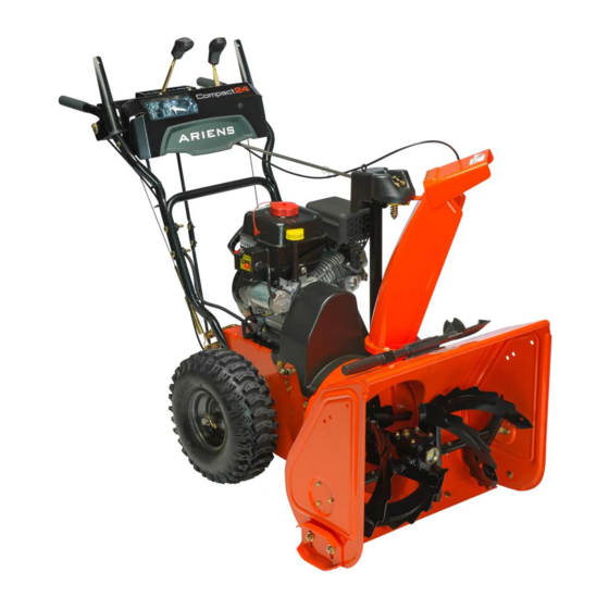
- Page 1 Sno-Thro ® Owner/Operator Manual Manuel Du Propriétaire/Utilisateur Models 920006 – Compact 24 920007 – Compact 20 920010 – Compact 24 03882500C 2/10 ENGLISH Printed in USA FRANÇAIS...
-
Page 2: Table Of Contents
Manuals in languages other than English may position and facing the direction of forward be obtained from your Dealer. Visit your travel. dealer or www.ariens.com for a list of languages available for your equipment. ENGINE MANUAL Manuals printed in languages other than... -
Page 3: Product Registration
UNAUTHORIZED REPLACEMENT 5. Review Limited Warranty Policy. PARTS 6. Fill out a Product Registration Card and return the card to the Ariens Company or Use only Ariens replacement parts. The go to www.ariens.com. replacement of any part on this vehicle with... -
Page 4: Safety
SAFETY PRACTICES AND LAWS WARNING: To avoid injury to hands Practice usual and customary safe working and feet, always disengage clutches, precautions, for the benefit of yourself and shut off engine, and wait for all others. Understand and follow all safety movement to stop before unclogging messages. -
Page 5: Safety Rules
1. WARNING! 3. DANGER! Read Owner/Operator Manual. ROTATING PARTS. Keep clear of auger while engine is running. • Read Operator’s Manual. OL1801 • Allow operation only by OS2080 properly trained adult, Keep people away from unit while never children. operating. Keep children out of •... - Page 6 DO NOT operate near drop-offs, ditches, or ALWAYS disengage attachment, stop unit embankments. Unit can suddenly turn over if and engine, remove key and allow moving a wheel is over the edge of a cliff or ditch, or if parts to stop before leaving operator’s an edge caves in.
- Page 7 Never leave a running unit unattended. When practical, remove gas-powered ALWAYS shut off engine before leaving unit. equipment from the truck or trailer and refuel ALWAYS remove key to prevent unauthorized it on the ground. If this is not possible, then use.
-
Page 8: Assembly
ASSEMBLY Unfold Handlebar (Figure 4) WARNING: AVOID INJURY. Read 1. Remove the lower and loosen the upper and understand the entire Safety hardware on the handlebar assembly. section before proceeding. 2. Loosen the hardware on the shift rod. 3. Put the speed selector lever in the sixth forward position. - Page 9 Install Discharge Chute (Figure 5) Install Discharge Chute Crank (Figure 6) 1. Grease underside of discharge chute ring (if not already greased). 1. Slide Chute Crank through the opening 2. Remove mounting hardware from the in the control panel. bottom of the chute pedestal. 2.
- Page 10 Check Tire Pressure Check Function of all Controls Check tire pressure and adjust to the Ensure unit runs and performs properly. Refer pressure listed on tire sidewall. to Operation. Run-in Attachment Belt CAUTION: Avoid injury! Explosive separation of tire and rim parts is 1.
-
Page 11: Controls And Features
CONTROLS AND FEATURES 920006, 007 – Briggs & Strattion 920010 – Subaru Figure 7 OS8145 OS8140 1. Attachment Clutch Lever 14. Gas Tank and Cap 2. Speed Selector 15. Electric Starter 3. Traction Drive Clutch Lever 16. Recoil Starter Handle 4. -
Page 12: Operation
NOTE: DO NOT twist key after it is inserted. locations. Dual Handle Interlock 920010 920006, 007 When Attachment Clutch and then Traction Drive Clutch are engaged, the Attachment Clutch will remain engaged (lever down) if released. To stop attachment, release Traction Drive Clutch and both clutches will disengage. - Page 13 2. Choke Open position: allows for normal operation. IMPORTANT: Gradually open choke after engine starts. 920006, 920007 OS1193 Forward: (6) Fastest (1) Slowest Reverse: (1) Slow (2) Fast IMPORTANT: DO NOT change motion from forward to reverse with clutch engaged.
- Page 14 Electric Starter Discharge Chute Deflector The electric starter will start a properly ALWAYS position discharge chute deflector choked and cranked engine when the starter at a safe angle before starting engine. button is pushed. Refer to Starting and Shut DO NOT throw snow any higher than Off on page 16.
-
Page 15: Filling Fuel Tank
FILLING FUEL TANK Wheel Unlocked WARNING: AVOID INJURY. Read and understand the entire Safety section before proceeding. GASOLINE IMPORTANT: ALWAYS use gasoline that meets the following guidelines: • Clean, fresh gasoline. • A minimum of 87 octane/87 AKI (91 RON). High altitude use may require a Axle Lock different octane. -
Page 16: Starting And Shut Off
5. Fill fuel tank to within 1/2 in. (1.2 cm) 6. Check Engine Fuel & Crankcase below bottom of filler neck with unleaded gasoline. 6. Replace Fuel Cap and tighten. WARNING: AVOID INJURY. Read 7. ALWAYS clean up any spilled fuel. and understand the entire Safety section before proceeding. -
Page 17: Snow Removal
Hand Lever. grounded outlet. IMPORTANT: DO NOT overload unit capacity IMPORTANT: Use only Ariens extension cord by attempting to clear snow at too fast a rate. (P/N 02483100) or an equilavent cord that is Use slow speed to clear deep or hard packed rated for a minimum of 13 amps, grounded, snow. -
Page 18: Maintenance
MAINTENANCE MAINTENANCE SCHEDULE Ariens Dealers will provide any service or adjustments which may be required to keep The chart below shows the recommended your unit operating at peak efficiency. Should maintenance schedule that should be engine service be required, contact an Ariens performed on a regular basis. -
Page 19: General Lubrication
If clutches do not engage or disengage IMPORTANT: Use only Ariens special gear properly, adjust or repair before operation lubricant L-2 (Part Number 00008000). (see Attachment Clutch/Brake Adjustment on Gearcase filler plug may require an application of Loc-Tite®... -
Page 20: Service And Adjustments
Grease OS8050 Figure 13 SERVICE AND ADJUSTMENTS 2. Adjust skid shoes by inserting a spacer of desired thickness under center of WARNING: AVOID INJURY. Read scraper blade, loosen skid shoe and understand the entire Safety hardware, slide skid shoe to flat surface. section before proceeding. -
Page 21: Shear Bolts
SHEAR BOLTS IMPORTANT: Use only Ariens shear bolts for replacement. Use of any other type of shear bolt may result in severe damage to unit and may void the warranty. Occasionally a foreign object may enter the auger/impeller housing and jam the auger, breaking shear bolts which secure the auger to the shaft (Figure 15). -
Page 22: Speed Selector Adjustment
3. Turn the speed selector arm straight down towards the ground as far as it will 4. For 920006 models with serial numbers less than 001201: Thread the adjustment pivot pin along the shift rod until it aligns with the mating hole on the speed selector arm. - Page 23 7. Remove hex bolts securing housing to frame (two on each side). Tip housing and frame apart on pivot pin. 8. Remove attachment drive belt from attachment pulley (hold brake away from belt). 1. Traction 5. Attachment 1. Pinion Gear 3.
-
Page 24: Traction Drive Belt Replacement
TRACTION DRIVE BELT REPLACEMENT NOTE: Housing and frame must be tipped apart and attachment drive belt removed from engine sheave in order to change traction drive belt (Figures 19, 20, 21 and 24) CAUTION: Always support Sno-Thro frame and blower housing when loosening the cap screws holding them together. - Page 25 Remove Attachment Cable Slack With the attachment clutch disengaged, 1. Remove the belt cover. check the attachment idler arm position 2. Loosen jam nut on cable adjustment here. The attachment idler arm should barrel, and then turn the adjustment lightly touch the frame. barrel down to shorten cable and remove all cable slack.
- Page 26 Adjust the Attachment Clutch Cable 2. Adjust cable length (See Figure 27). Spring Extension a. Loosen jam nut on cable. b. To increase spring extension, 1. Check the attachment clutch cable adjust barrel down the cable and spring extension. tighten jam nut. Measure the length of the attachment c.
-
Page 27: Traction Drive Clutch Adjustment
Check Belt Finger Clearance (Figure 29) Traction Clutch Lever 7-1/2 – 8 in. 1. With clutch lever engaged, the belt (19.0 – 20.3 cm) finger located opposite the belt idler must be less than 1/8 in. (3,2 mm) from belt, but not touching the belt. To adjust belt finger, loosen the bolts and move the finger to the proper position. - Page 28 10. Remove three screws holding friction disc to carrier bearing. 11. Remove old friction disc. Put the new friction disc in place, cup side to carrier bearing. 12. Reinstall three screws into new friction disc and carrier bearing. Torque to 5 –...
-
Page 29: Storage
ACCESSORIES condition. Store unit in a cool, dry protected area. See your authorized Ariens dealer to add the additional accessories available to your LONG TERM Sno-Thro model. Clean unit thoroughly with mild soap and low Part No. -
Page 30: Troubleshooting
TROUBLESHOOTING PROBLEM PROBABLE CAUSE CORRECTION Engine will 1. Fuel tank is empty. 1. Fill fuel tank. 2. Fuel shut-off valve 2. Open fuel shut-off valve. closed. crank/start. 3. Build up of dirt and 3. Clean area around residue around governor/carburetor. governor/carburetor. -
Page 31: Specifications
SPECIFICATIONS Model Number 920006 920007 920010 Description Compact 24 Compact 20 Compact 24 Engine Briggs & Stratton Briggs & Stratton Subaru SX17 900 Series 900 Series Gross Torque* - ft-lbs (N-m) 9.0 (12.2) 9.0 (12.2) Displacement - in. (cc) 12.5 (205) 12.5 (205) - Page 32 GB - 32...
-
Page 33: Warranty
The battery pack and/or battery subassemblies on AMP series electric Sno-Thro products is/are war- ranted to the original purchaser for two years from the date of purchase. Ariens will replace, free of charge to the original purchaser, any battery pack and/or battery subassembly that fails due to defect in material or workmanship for one year after the date of purchase. - Page 34 Canada. In all other countries, contact place of purchase for warranty information. Disclaimer Ariens may from time to time change the design of its products. Nothing contained in this warranty shall be construed as obligating Ariens to incorporate such design changes into previously manufactured products, nor shall such changes be construed as an admission that previous designs were defective.
- Page 35 Ariens Company 655 West Ryan Street Brillion, WI 54110-1072 920-756-2141 www.ariens.com...