
Related Manuals for GE Spacemaker GSM1800J Series


Summary of Contents for GE Spacemaker GSM1800J Series
- Page 1 GE Consumer Products TECHNICAL SERVICE GUIDE Spacemaker 18-In. Built-In Compact Dishwasher MODEL SERIES: GSM1800J PUB # 31-9114 11/03...
- Page 2 If grounding wires, screws, straps, clips, nuts, or washers used to complete a path to ground are removed for service, they must be returned to their original position and properly fastened. GE Consumer Products Technical Service Guide Copyright © 2003 All rights reserved.
-
Page 3: Table Of Contents
TABLE OF CONTENTS Bottom Door Seal ....................18 Component Locator Views ..................7 Control Panel Features ..................6 Detergent/Rinse Module ..................15 Dishwasher Components ................... 10 Dishwasher Tub Seal ..................19 Door Assembly ..................... 16 Door Panel ......................14 Door Switch and Latch Assembly ................ 12 Drain Pump Assembly .................. -
Page 4: Introduction
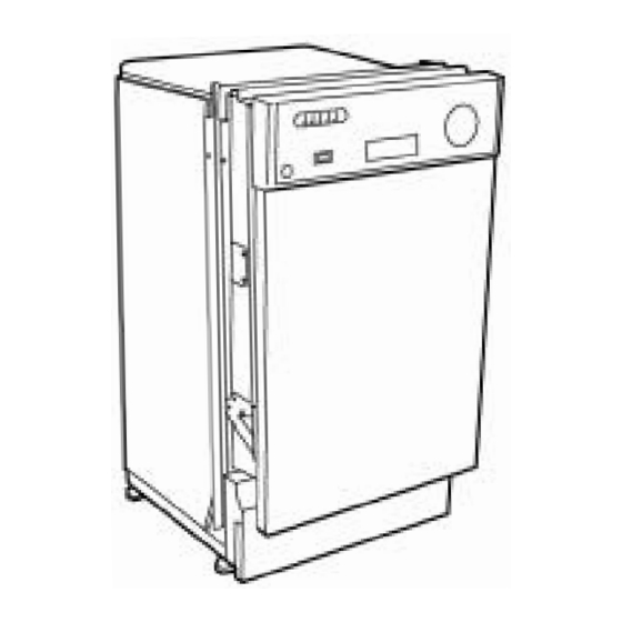
Introduction The new Spacemaker 18" Built-In Dishwasher has a compact size, allowing the unit to fit in areas as small as 18 inches (45.72 cm) wide, 22 inches (55.88 cm) long, and 34 inches (86.36 cm) high. It is compact in size, yet still delivers the performance of larger units. With ®... -
Page 5: Nomenclature
Nomenclature Model Number G S M 1 8 0 0 J 0 0 W W Brand P = Profile E = General Electric - NATM Exterior Color G = General Electric BB = Black Product Type CC = Bisque CD - Counter Top DW = Dishwasher SS = Stainless Steel SD = Standard... -
Page 6: Control Panel Features
Control Panel Features Heated Dry Switch Control Timer Door Latch Switch Control Timer: Close the dishwasher door and turn the control timer knob to the desired setting. START Water fill begins and approximately 30 seconds later, the wash action begins. This cycle is specifically designed for heavy soiled cookware with dried-on or baked-on soils. -
Page 7: Component Locator Views
Component Locator Views Front View Control Panel Insulation Door Tension Spring Access Panel Control Panel View Static Vent Control Timer Heated Dry Switch Door Latch Switch – 7 –... - Page 8 Interior View (With Racks) Top Rack Bottom Rack Detergent/Rinse Module Static Dry Vent Detergent/Rinse Module Compartment View Detergent Compartment Sight Glass Rinse Agent Cap Compartment Lid – 8 –...
- Page 9 Interior View of Basin (With Racks Removed) Right Side View (Insulation Removed) Spray Arm Fill Funnel Fill Hose Heating Element Pressure Switch Hose Filter Assembly Clamp Nut Micro-filter Bottom View (Looking Up) Sump Drain Pump Motor Pump Capacitor Assembly – 9 –...
-
Page 10: Dishwasher Components
Dishwasher Components Throughout this manual, features and appearance may vary from your model. Timer WARNING: Always turn off the electric power supply before servicing any electrical component, making ohmmeter checks, or replacing any parts. Note: All voltage checks should be made with a voltmeter having a full scale range of 130 volts or higher. -
Page 11: Heated Dry Switch
8. Release the door latch and allow the control panel cover to hang against the dishwasher door. Timer Align the threaded holes marked in step 3 with the holes in the control panel. Control Panel Heated Dry Switch 9. Disconnect the ground wire from the timer. The heated dry switch is used to turn the heating element ON or OFF. -
Page 12: Door Switch And Latch Assembly
7. Disconnect the 2 wire terminals from the heated dry switch and remove the switch. 7. Remove the 4 screws that connect the door switch mounting bracket to the control panel cover. 8. Reverse the above procedure to install. Door Switch and Latch Assembly The latch and switch assembly are located on the door assembly behind the control panel cover. -
Page 13: Static Dry System
9. Remove the door switch from the door switch 4. Remove the static vent channel cover and mounting bracket. assembly as shown below. Inspect the cover for hard water/lime deposits or debris and clean if necessary. Switch Cover Bracket Channel 10. -
Page 14: Door Panel
Installation Door Panel 1. Insert the static vent channel through the The door panel covers the door to the dishwasher static vent door hole. and protects the detergent/rinse module electronics. Removal 1. Disconnect power. Hole Channel 2. Open the dishwasher door. 3. -
Page 15: Detergent/Rinse Module
When activated for the second time in a cycle, the Detergent/Rinse Module lever lifts the connecting rod by the notch, lifting the rinse dispenser plunger (4) and releasing the The detergent rinse module automatically rinse agent. When deactivated, the lever returns dispenses both the detergent and the rinse agent to its original starting position. -
Page 16: Door Assembly
5. Remove the 3 screws and top mounting Door Assembly bracket. Removal and Replacement Bracket 1. Disconnect power. 2. Remove the 6 screws that connect the control panel cover to the dishwasher door. (See Timer, step 6.) 3. Close the dishwasher door. 4. - Page 17 11. Remove the bolt, nut, and ground wire from 14. Pull the spring and spring bolt key from the the door. mounting bracket. 12. Pull the wire harness from the door. 15. Lift the bottom of the spring loop from the hinge arm stud.
-
Page 18: Bottom Door Seal
21. Repeat steps 3 through 10 to remove the left- side door hinge assembly. 22. Remove the dishwasher door from the dishwasher. Hook 23. Reverse the above procedure to install. Bottom Door Seal The bottom door seal prevents water leakage. Hinge The seal is fitted in a pinched metal groove at the bottom of the dishwasher door. -
Page 19: Dishwasher Tub Seal
Dishwasher Tub Seal Heating Element The dishwasher tub seal prevents water leakage. The heating element maintains water temperature The seal is fitted in a seal channel that lines the during the wash and rinse cycles and heats the rim of the dishwasher tub. air during the static dry cycle. -
Page 20: Fill Funnel
Heating Element 11. Reverse the above procedure to install. 7. Remove the nut and ground wire. Fill Funnel 8. Remove the lock-washer and spacer bracket. The fill funnel is mounted on the left side of the tub. Its purpose is to provide a method of supplying water for the wash and rinse cycles. -
Page 21: Water Valve
4. Loosen the clamp and disconnect the fill funnel Shown with access panel removed. hose from the fill funnel. 5. Remove the fill funnel from the dishwasher. Fill Funnel Clamp Toe-Kick Panel 3. Disconnect the incoming water line from the water fill valve port. -
Page 22: Pressure Switch
6. Disconnect the 2 terminal lugs from the water As the dishwasher basin fills with water, the air fill valve assembly. pressure in the pressure switch hose increases. Normally, the timer regulates the amount of time the water fill valve remains open. If the water fill valve remains energized, the overfilling of the basin increases the air pressure in the pressure switch hose, causing the pressure switch to open... -
Page 23: Drain Pump Assembly
3. Remove the capillary tube from the float switch. 3 Terminal Lugs Pressure Switch Hose 6. Reverse the above procedure to install. Drain Pump Assembly 4. Turn the float switch clockwise to align the mounting tab vertically with the mounting hole The drain pump assembly is located under the tub and remove the float switch from the at the left, rear corner. -
Page 24: Motor Pump Assembly
Nut Plate Mounting Bracket 2 Screws 2 Lock-washers 5. Remove the 2 bolts, lock-washer, and nuts. 9. Reverse the above procedure to install. Motor Pump Assembly The motor pump assembly is located under the tub behind the sump assembly. This dishwasher model uses a capacitor start induction motor. - Page 25 Caution: The clamp is easily damaged during removal and should not be reused. Replace the old clamp with a new universal clamp (part number: WH1X2036). 7. Remove the clamp from the motor washer arm interconnect hose. Connector Interconnect Hose Clamp Caution: The clamp is easily damaged during removal and should not be reused.
-
Page 26: Sump Assembly
Sump Assembly The sump assembly consists of the filter assembly, micro-filter, sump clamping nut, sump gasket, and sump. The filter assembly prevents large particles from reaching the micro-filter and the micro-filter prevents small particles from reaching the sump. The filter assembly rests Lock Nut above the sump and the micro-filter sits above the sump basin. - Page 27 Note: The sump clamping nut turns counterclockwise and may be difficult to remove. It may be necessary to insert a screw driver or other tool between the clamping nut tabs to enable you to apply sufficient torque to break the factory seal.
-
Page 28: Troubleshooting
Troubleshooting WARNING: Always turn off the electric power Troubleshooting the Door Switch supply before servicing any electrical component, making ohmmeter checks, or replacing any parts. The door switch can be tested using an ohmmeter and the strip circuit. Note: All voltage checks should be made with a 1. - Page 29 Troubleshooting the Heated Dry Switch Troubleshooting the Heating Element The heated dry switch can be tested using an The heating element maintains water temperature ohmmeter, along with the wiring schematic and during the wash and rinse cycles and heats the air selector switch chart.
- Page 30 Timer Strip Circuit Troubleshooting the Timer PRESSURE If the timer is suspected of faulty operation, refer SWITCH to the Timer Cycle Chart and Timer Strip Circuit and proceed as follows: 1. Index the timer to the first increment of the Pots and Pans cycle.
- Page 31 Troubleshooting the Wash Pump Motor Troubleshooting the Water Fill Valve The wash pump motor does not start immediately If the water fill valve is suspected of faulty when the dishwasher cycle has started. The tub operation, refer to the strip circuit and proceed as will begin filling with water and the motor will start follows: approximately 40 seconds into the fill cycle.
- Page 32 2. If the water does not touch the heating ele- Water Fill Valve Strip Circuit ment, disconnect power, close the door, and check the incoming water pressure. A mini- PRESSURE mum incoming water pressure of 20 PSI is SWITCH needed to properly fill the dishwasher basin. Water Fill Valve Will Not Shut Off 1.
- Page 33 The wiring diagram, schematic, and timer cycle Troubleshooting Check List chart are a necessity when making electrical checks. In most cases, an ohmmeter will handle The troubleshooting check list is common for all all the tests necessary. dishwasher models. They use different parts to accomplish the same thing and diagnosis will To verify the setup of any particular cycle of remain similar.
- Page 34 SYMPTOM CHECK FOR THE REMEDY FOLLOWING No heat during the dry 1. Defective heat switch. 1. Replace the heat switch. cycle. 2. Defective heater element. 2. Replace the heater element. 3. Defective timer. 3. Replace the timer. 4. Damaged or defective wiring. 4.
- Page 35 SYMPTOM CHECK FOR THE REMEDY FOLLOWING Poor washability. 1. Improper loading of dishes, pots, 1. Instruct the customer on pans, and nesting of silverware. proper loading of the dishwasher. Refer to the owners manual. 2. Defective spray arm. 2. Check spray arm for proper rotation.
- Page 36 SYMPTOM CHECK FOR THE REMEDY FOLLOWING Noisy pump assembly. 1. Debris in bottom of tub sump area. 1. Clean out the sump area. 2. Pump parts were not properly 2. Inspect the pump and installed. correct and installation errors. 3. Impellers are not properly 3.
-
Page 37: Washability Complaints
Washability Complaints Hot Water – Ample supply of water at a minimum Rinse Agent – Use rinse agent if spotting or temperature of 120 °F (48.9 °C) is necessary. Do drying is a problem. A rinse agent will improve the not use dishwasher soon after using clothes water sheeting action and drying performance. -
Page 38: Schematic
Schematic WARNING: Power must be disconnected before servicing the appliance. PRESSURE SWITCH FLOAT SWITCH DRAIN PUMP INLET VALVE WASH PUMP DISPENSER (YELLOW (WHITE HOUSING) HOUSING) HEATER OPTION SWITCH TIMER TIMER MOTOR DOOR SWITCH 120V 60Hz Note: Schematic diagram subject to change. Please refer to diagram supplied with product located inside product console. - Page 39 Illustrated Parts Catalog – 39 –...
- Page 40 – 40 –...
- Page 41 – 41 –...
- Page 42 – 42 –...
- Page 43 VIEW DRAWING CATALOG DESCRIPTION QUANTITY NUMBER NUMBER NUMBER 2903007105 WD12X10164 MAIN CONDUIT 2903013102 WD01X10240 O RING 2903016010 WD01X10241 GUIDE CASING 2903014012 WD01X10242 RING NUT W/GASKET 2903017007 WD12X10165 MAIN CONDUIT-UPPER SPRAY 2903007109 WD12X10166 CONDUIT - UPPER SPRAY 2907340004 WD22X10039 UPPER SPRAY ASM & GASKET 2903024004 WD12X10167 FILTER ASM...
- Page 44 VIEW DRAWING CATALOG DESCRIPTION QUANTITY NUMBER NUMBER NUMBER 2902010001 WD03X10024 DOOR HINGE SPRING 2902041002 WD01X10250 DOOR HINGE PIN 2902061003 WD14X10018 HINGE ASSEMBLY 2902061002 WD14X10020 RIGHT HINGE ASM 2902061001 WD14X10019 LEFT HINGE ASM 2904001043 WD01X10248 HARNESS ASM 2904008011 WD12X10174 DETERGENT DISPENSER 2903015002 WD08X10050 DOOR GASKET ASM...
- Page 45 Any part of the dishwasher which fails due to a defect in materials or workmanship. During From the date of the this full one-year warranty, GE will also provide, free of charge, all labor and in-home service original purchase to replace the defective part.