Table of Contents
Advertisement
ELECTROLUX HOME PRODUCTS
Corso Lino Zanussi,30
I - 33080 PORCIA /PN (ITALY)
Tel +39 0434 394850
Fax +39 0434 394096
SOI
Edition: 03.2006
SOI 03.06 FV
Publication No.
599 36 78-45
EN/SERVICE/FV
SERVICE MANUAL
MICROWAVE OVENS
Microwave Oven
(Middle Grill)
MCD2660E (EU)
MCD2661E (EU)
MCD2660E (UK)
EMS2685 (EU)
EMS2685 (UK)
ZM266ST (UK)
JMW9161 (A,D)
MO926G (I)
MOA4226 (D,K)
599 36 78-45
Advertisement
Table of Contents

Related Manuals for Electrolux MCD2660E


Summary of Contents for Electrolux MCD2660E
- Page 1 SERVICE MANUAL MICROWAVE OVENS Microwave Oven (Middle Grill) ELECTROLUX HOME PRODUCTS Publication No. Corso Lino Zanussi,30 MCD2660E (EU) I - 33080 PORCIA /PN (ITALY) 599 36 78-45 MCD2661E (EU) MCD2660E (UK) Tel +39 0434 394850 EMS2685 (EU) Fax +39 0434 394096...
- Page 2 SOI 03.06 FV 2/38 599 36 78-45...
-
Page 3: Table Of Contents
TABLE OF CONTENTS CAUTION, MICROWAVE RADIATION / GENERAL IMPORTANT INFORMATION .......4 SERVICING / GENERAL INFORMATION ..................5 PRODUCT SPECIFICATIONS......................6 APPEARANCE VIEW ........................7 OPERATING SEQUENCE ......................13 FUNCTION OF IMPORTANT COMPONENTS................15 TROUBLESHOOTING CHART ......................17 TEST PROCEDURE........................18 CONTROL PANEL ASSEMBLY.....................26 SERVICING ............................27 COMPONENT REPLACEMENT AND ADJUSTMENT PROCEDURE ..........28 MICROWAVE MEASUREMENT ....................34 TEST DATA A GLANCE / WIRING / RE-WIRING .................35 SCHEMATIC DIAGRAMS ......................36... -
Page 4: Caution, Microwave Radiation / General Important Information
CAUTION CAUTION MICROWAVE RADIATION Personnel should not be exposed to the microwave energy which may radiate from the magnetron or other microwave generating devices if it is improperly used or connected. All input and output microwave connections, waveguides, flanges and gaskets must be secured. Never operate the device without a microwave energy absorbing load attached. -
Page 5: Servicing / General Information
SERVICING WARNING TO SERVICE PERSONNEL Microwave ovens contain circuitry capable of producing very high voltage and current. Contact with the following parts will result in electrocution High voltage capacitor, High Voltage transformer, Magnetron, High voltage rectifier assembly, High voltage wires. REMEMBER TO CHECK 3D REMEMBER TO CHECK 4R 1) Disconnect the supply. -
Page 6: Product Specifications
PRODUCT SPECIFICATIONS SPECIFICATION ITEM DESCRIPTION Power Requirements 230 Volts(EU)/230-240 Volts(UK) 50 Hertz Single phase, 3 wire earthed Power Consumption Microwave cooking 1.42kW Approx. 6.3A 1.4/6.2 1.42/6.3 Grill cooking 1.0kW Approx. 4.2A 1.0/4.3 1.0/4.2 Dual cooking 2.4kW Approx. 10.2A 2.35/10.4 2.4/10.2 Power Output 900W watts nominal of RF microwave energy (measured by way of IEC 60705) -
Page 7: Appearance View
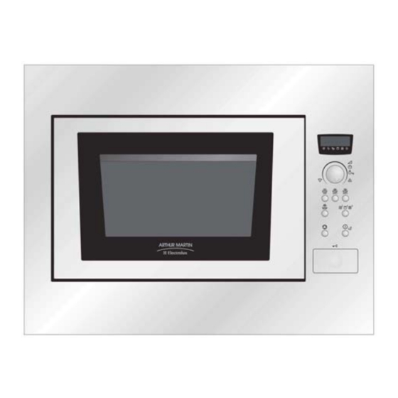
APPEARANCE VIEW OVEN 1 Front trim 2 Oven lamp 3 Control panel 4 Door open button 5 Waveguide cover 6 Oven cavity 7 Seal packing 8 Door seals and sealing surfaces. 9 Fixing points (4 points) 10 Ventilation openings 11 Outer cover 12 Rear cabinet 13 Power supply cord support clip. - Page 8 APPEARANCE VIEW CONTROL PANEL MCD2660E / MCD2661E / MOA4226 1 Digital Display 2 Indicators The appropriate indicator will flash or light up, just above each symbol according to the instruction. When an indicator is flashing, press the appropriate button (having the same symbol) Or carry out the necessary operation.
- Page 9 APPEARANCE VIEW CONTROL PANEL EMS2685 1 Digital Display 2 Indicators The appropriate indicator will flash or light up, just above each symbol according to the instruction. When an indicator is flashing, press the appropriate button (having the same symbol) or carry out the necessary operation.
- Page 10 APPEARANCE VIEW CONTROL PANEL ZM266ST 1 Digital Display 2 Indicators The appropriate indicator will flash or light up, just above each symbol according to the instruction. When an indicator is flashing, press the appropriate button (having the same symbol) or carry out the necessary operation.
- Page 11 APPEARANCE VIEW CONTROL PANEL JMW9161 1 Digital Display 2 Indicators The appropriate indicator will flash or light up, just above each symbol according to the instruction. When an indicator is flashing, press the appropriate button (having the same symbol) or carry out the necessary operation.
- Page 12 APPEARANCE VIEW CONTROL PANEL MO926G 1 Digital Display 2 Indicators The appropriate indicator will flash or light up, just above each symbol according to the instruction. When an indicator is flashing, press the appropriate button (having the same symbol) or carry out the necessary operation.
-
Page 13: Operation Sequence
OPERATION SEQUENCE OFF CONDITION Closing the door activates the door interlock switch (monitored latch switch). IMPORTANT When the oven door is closed, the monitor switch contacts COM - NC must be open. When the microwave oven is plugged in a wall outlet (230V (EU) / 230-240V (UK) 50Hz), the noise filter is energized. -
Page 14: Grill Cooking Condition
OPERATION SEQUENCE HIGH, MEDIUM HIGH, MEDIUM, MEDIUM LOW, LOW COOKING When the microwave oven is preset for variable cooking power, the line voltage is supplied to the power transformer intermittently within a 32-second time base through the vary contact. The following levels of microwave power are given. -
Page 15: Function Of Important Components
FUNCTION OF IMPORTANT COMPONENTS DOOR OPEN MECHANISM The door can be opened by pushing the door open button. MONITORED LATCH SWITCH (SW1) DOOR 1. When the oven door is closed, the contacts LATCH HOOK MONITOR (COM - NO) must be closed. SWITCH (SW2) 2. - Page 16 FUNCTION OF IMPORTANT COMPONENTS FAN MOTOR The fan motor drives a blade which draws external cool air. This cool air is directed through the air vanes surrounding the magnetron and cools the magnetron. This air flows through the oven cavity to remove steam and vapours given off from the heating foods.
-
Page 17: Troubleshooting Chart
TROUBLESHOOTING CHART When troubleshooting the microwave oven, it is helpful to follow the Sequence of Operation in performing the checks. Many of the possible causes of trouble will require that a specific test be performed. These tests are given a procedure letter which will be found in the “Test Procedure” section. IMPORTANT: If the oven becomes inoperative because of a blown fuse F2. -
Page 18: Test Procedure
TEST PROCEDURES PROCEDURE LETTER COMPONENT TEST MAGNETRON TEST NEVER TOUCH ANY PART IN THE CIRCUIT WITH YOUR HAND OR AN INSULATED TOOL WHILE THE OVEN IS IN OPERATION. CARRY OUT 3D CHECK Isolate the magnetron from high voltage circuit by removing all leads connected to the filament terminal. -
Page 19: B Power Transformer Test
TEST PROCEDURES PROCEDURE LETTER COMPONENT TEST NOTE: The operation time of the microwave oven is “t + 3” sec. 3 seconds are needed for magnetron filament heat-up time. Measuring method: 1. Measure the initial temperature of the water before the water is added to the vessel. -
Page 20: D High Voltage Capacitor Test
TEST PROCEDURES PROCEDURE LETTER COMPONENT TEST HIGH VOLTAGE RECTIFIER ASSEMBLY TEST CARRY OUT 3D CHECKS. Isolate the high voltage rectifier assembly from the HV circuit. The high voltage rectifier can be tested using an ohmmeter set to its highest range. Connect the ohmmeter across the terminal B+C of the high voltage rectifier and note the reading obtained. -
Page 21: Test Procedures
TEST PROCEDURES PROCEDURE LETTER COMPONENT TEST SWITCH TEST CARRY OUT 3D CHECKS. Isolate the switch to be tested and using an ohmmeter check between the terminals as described in the following table. Table: Terminal Connection of Switch Plunger Operation COM to NO COM to NC COM;... - Page 22 TEST PROCEDURES PROCEDURE LETTER COMPONENT TEST BLOWN FUSE F8A (F2) CARRY OUT 3D CHECKS If the fuse F8A (F2) is blown when the door is opened, check the primary latch switch, monitor switch and monitor resistor. If the fuse F8A (F2) is blown by incorrect door switching replace the defective switch(es) and the fuse F8A (F2).
-
Page 23: Touch Control Panel Assembly Test
TEST PROCEDURES PROCEDURE LETTER COMPONENT TEST 3. Connect the voltmeter, set to 250V AC, across the motor terminals. (Refer to the relevant motor test procedure or pictorial diagram for the correct terminal numbers.) 4. Arrange the meter in a position where it can be read during the test. (Do not touch the meter, meter leads or oven circuitry while the oven is active.) 5. -
Page 24: M Relay Test
TEST PROCEDURES PROCEDURE LETTER COMPONENT TEST 4. Relay Unit a) Grill cooking is not possible. SWITCH UNIT TEST If the display fails to clear when the STOP key is depressed, first verify the lead wire harness is marking good contact, verify that the stop switch operates properly; that is the contacts are closed when the door is closed and open when the door is open. - Page 25 TEST PROCEDURES PROCEDURE LETTER COMPONENT TEST GRILL HEATING ELEMENT TEST CARRY OUT 3D CHECKS Before carrying out the following tests make sure the heating element is cooled completely. 1. Resistance of heating element. Disconnect the wire leads to the heating element to be tested. Using ohmmeter with low resistance range.
-
Page 26: Control Panel Assembly
CONTROL PANEL ASSEMBLY OUTLINE OF CONTROL PANEL The touch control section consists of the following units as shown in the touch control panel circuit. (1) Switch Unit (2) Control Unit (3) LED Unit (4) Relay Unit The principal functions of these units and the signals communicated among them are explained below. Switch Unit The switch unit is composed of a matrix, signals generated in the LSI are sent to the switch unit through P22, P23 and P24. -
Page 27: Servicing
SERVICING 1. Precautions for Handling Electronic 5) Re-connect the power supply cord after the Components outer case is installed. This unit uses CMOS LSI in the integral part of the 6) Run the oven and check all functions. circuits. When handling these parts, the following A. -
Page 28: Component Replacement And Adjustment Procedure
COMPONENT REPLACEMENT AND ADJUSTMENT PROCEDURE WARNING: Avoid possible exposure to microwave energy. Please follow the instructions below before operating the oven. 1. CARRY OUT 3D CHECKS. 2. Make sure that a definite "click" can be heard 2. Door hinges or latch hook is damaged. when the microwave oven door is unlatched. - Page 29 COMPONENT REPLACEMENT AND ADJUSTMENT PROCEDURE HIGH VOLTAGE COMPONENTS REMOVAL (HIGH VOLTAGE CAPACITOR AND HIGH VOLTAGE RECTIFIER ASSEMBLY) To remove the components, proceed as 8. Remove the high voltage capacitor from the capacitor follows. holder. 1. CARRY OUT 3D CHECKS 9. Disconnect the high voltage wire B and the high voltage 2.
- Page 30 COMPONENT REPLACEMENT AND ADJUSTMENT PROCEDURE FAN MOTOR REPLACEMENT REMOVAL CAUTION: CAUTION: Do not reuse the removed fan blade as the fixing hole may be oversize. 1. CARRY OUT 3D CHECKS. 2. Remove the one (1) screw holding the noise 13. Remove the two (2) screws holding the fan motor filter to the chassis support.
-
Page 31: Oven Lamp Removal
COMPONENT REPLACEMENT AND ADJUSTMENT PROCEDURE OVEN LAMP REMOVAL 1. CARRY OUT 3D CHECKS. 2. Disconnect the wire lead from the oven lamp 3. Lift up the oven lamp from the clips of the air intake duct. 4. Now, the oven lamp is free. Lock Bulb Socket... - Page 32 COMPONENT REPLACEMENT AND ADJUSTMENT PROCEDURE MONITORED LATCH SWITCH, MONITOR SWITCH AND STOP SWITCH REMOVAL 1. CARRY OUT 3D CHECKS. MONITOR SWITCH 2. Remove the control panel assembly referring to "CONTROL PANEL ASSEMBLY REMOVAL". 3. Disconnect the all leads from the MONITORRED switches.
-
Page 33: Door Disassembly
COMPONENT REPLACEMENT AND ADJUSTMENT PROCEDURE DOOR DISASSEMBLY REMOVAL Note: After any service to the door; 1. Disconnect the power supply cord. (A) Make sure that monitored latch switch, stop 2. Open the door slightly and remove the switch and monitor switch are operating properly. (Refer built in frame assembly(Ref: to chapter to chapter “Test Procedures , Switch Test page 21”.). -
Page 34: Microwave Measurement
COMPONENT REPLACEMENT AND ADJUSTMENT PROCEDURE INNER SEALER FILM Door film Backing film Installation 1. Tear away the backing film. 3. Put the pasted side of the inner sealer film on the door panel. Figure C-6. Inner Sealer Film MICROWAVE MEASUREMENT After adjustment of door latch switches, monitor Recommended instruments are: switch and door are completed individually or... -
Page 35: Test Data A Glance / Wiring / Re-Wiring
TEST DATA AT A GLANCE Parts Symbol Value / Data Thermal cut-out (OVEN) TC01 145°C Oven lamp 240-250V 25W High voltage capacitor 1.02µF AC 2100V Ω Magnetron Filament < 1 ∞ Filament – chassis ohm. Ω Power transformer Filament winding < 1 Ω... -
Page 36: Schematic Diagrams
SCHEMATIC DIAGRAMS Figure 0-1 Oven Schematic-OFF Condition, Door Closed. Figure 0-2 Oven Schematic-ON Condition, Door Closed (Microwave Cooking) . SOI 03.06 FV 36/38 599 36 78-45... - Page 37 SCHEMATIC DIAGRAMS Figure 0-3 Oven Schematic-ON Condition, Door Closed (Grill cooking). Figure 0-4 Oven Schematic-ON Condition, Door Closed (Dual Cooking) . SOI 03.06 FV 37/38 599 36 78-45...
-
Page 38: Pictorial Diagram
PICTORIAL DIAGRAMS Switch PWB Figure S-1 Pictorial Diagram . SOI 03.06 FV 38/38 599 36 78-45...