Table of Contents
Advertisement
ELECTROLUX HOME PRODUCTS
Corso Lino Zanussi,30
I - 33080 PORCIA /PN (ITALY)
Tel +39 0434 394850
Fax +39 0434 394096
SOI
Edition: 01.2005
SOI 01.05 FV
MICROWAVE OVENS
Publication No.
599 36 78-06
EN/SERVICE/FV
SERVICE MANUAL
Microwave Oven
(Compact Solo)
MC1751E/MC1761E (EU)
MC1751E/MC1761E (UK)
EMS1750X/EM1760X (UK)
QN4025/QN4026
(SCANDINAVIA)
JMW1051/JMW1061 (A,D)
MOA4217 (D,K)
599 36 78-06
Advertisement
Table of Contents

Related Manuals for Electrolux MC1751E


Summary of Contents for Electrolux MC1751E
-
Page 1: Microwave Ovens
SERVICE MANUAL MICROWAVE OVENS Microwave Oven (Compact Solo) ELECTROLUX HOME PRODUCTS Publication No. Corso Lino Zanussi,30 MC1751E/MC1761E (EU) I - 33080 PORCIA /PN (ITALY) 599 36 78-06 MC1751E/MC1761E (UK) EMS1750X/EM1760X (UK) Tel +39 0434 394850 QN4025/QN4026 Fax +39 0434 394096... - Page 2 SOI 01.05 FV 2/33 599 36 78-06...
-
Page 3: Table Of Contents
TABLE OF CONTENTS CAUTION, MICROWAVE RADIATION / GENERAL INFORMATION ..........4 SERVICING............................3 PRODUCT SPECIFICATIONS......................6 APPEARANCE VIEW........................7 OPERATING SEQUENCE ......................10 FUNCTION OF IMPORTANT COMPONENTS................12 TROUBLESHOOTING CHART......................13 TEST PROCEDURE ........................14 CONTROL PANEL ASSEMBLY.....................22 COMPONENT REPLACEMENT AND ADJUSTMENT PROCEDURE ..........24 MICROWAVE MEASUREMENT....................30 TEST DATA A GLANCE / WIRING / RE-WIRING .................31 SCHEMATIC DIAGRAMS ......................32 PICTORIAL DIAGRAM........................33 SOI 01.05 FV... -
Page 4: Caution, Microwave Radiation / General Information
CAUTION CAUTION MICROWAVE RADIATION Personnel should not be exposed to the microwave energy which may radiate from the magnetron or other microwave generating devices if it is improperly used or connected. All input and output microwave connections, waveguides, flanges and gaskets must be secured. Never operate the device without a microwave energy absorbing load attached. -
Page 5: Servicing
SERVICING WARNING TO SERVICE PERSONNEL Microwave ovens contain circuitry capable of producing very high voltage and current. Contact with the following parts will result in electrocution High voltage capacitor, High Voltage transformer, Magnetron, High voltage rectifier assembly, High voltage wires. REMEMBER TO CHECK 3D REMEMBER TO CHECK 4R 1) Disconnect the supply. -
Page 6: Product Specifications
PRODUCT SPECIFICATIONS SPECIFICATION ITEM DESCRIPTION Power Requirements 230 Volts(EU)/230-240 Volts(UK) 50 Hertz Single phase, 3 wire earthed Power Consumption 1.2 kW Power Output 800W watts nominal of RF microwave energy (measured by way of IEC 60705) Operating frequency of 2450 MHz Case Dimensions Width 454mm(including screws) Height 357mm (including foot) -
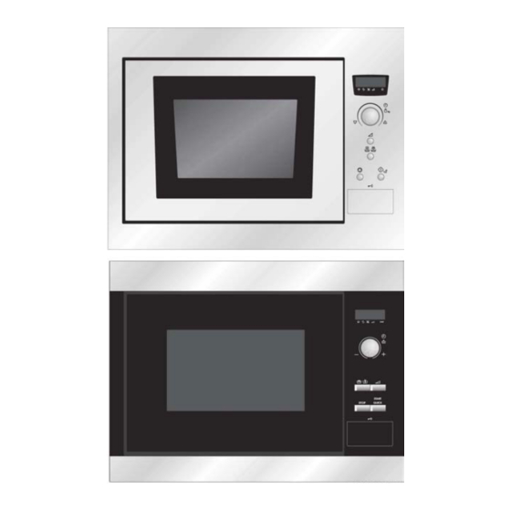
Page 7: Appearance View
1. Place the roller stay on the floor of the oven cavity, engaging shaft into turntable motor shaft. CONTROL PANEL 2. Then place the turntable on roller MC1751E/MC1761E/MOA4117 stay. 1 Digital Display 2 Indicators The appropriate indicator will flash or light up, just above each symbol according to the instruction. - Page 8 APPEARANCE VIEW CONTROL PANEL EMS1750X/EMS1760X 1 Digital Display 2 Indicators The appropriate indicator will flash or light up, just above each symbol according to the instruction. When an indicator is flashing, press the appropriate button (having the same symbol) or carry out the necessary operation. Stir Turn oven Weight...
- Page 9 APPEARANCE VIEW QN4025/QN4026 1 Digital Display 2 Indicators The appropriate indicator will flash or light up, just above each symbol according to the instruction. When an indicator is flashing, press the appropriate button (having the same symbol) or carry out the necessary operation. Stir Turn oven Weight...
-
Page 10: Operation Sequence
OPERATION SEQUENCE MICROWAVE OFF CONDITION Closing the door activates the door interlock switch (monitored latch switch). IMPORTANT When the oven door is closed, the monitor switch contacts COM - NC must be open. When the microwave oven is plugged in a wall outlet (230V/ 230-240v 50Hz), the noise filter is energized. Figure 0-1 on page 32 NOTE: When the oven door is opened, the oven lamp comes on at this time. - Page 11 OPERATION SEQUENCE HIGH, MEDIUM HIGH, MEDIUM, MEDIUM LOW, LOW COOKING When the microwave oven is preset for variable cooking power, the line voltage is supplied to the power transformer intermittently within a 32-second time base through the vary contact. The following levels of microwave power are given.
-
Page 12: Function Of Important Components
FUNCTION OF IMPORTANT COMPONENTS DOOR OPEN MECHANISM The door can be opened by pushing the door open button. MONITORED LATCH SWITCH (SW1) 1. When the oven door is closed, the contacts Door Latch hook (COM - NO) must be closed. 2. -
Page 13: Troubleshooting Chart
TROUBLESHOOTING CHART When troubleshooting the microwave oven, it is helpful to follow the Sequence of Operation in performing the checks. Many of the possible causes of trouble will require that a specific test be performed. These tests are given a procedure letter which will be found in the “Test Procedure” section. IMPORTANT: If the oven becomes inoperative because of a blown fuse F1. -
Page 14: Test Procedure
TEST PROCEDURES PROCEDURE LETTER COMPONENT TEST MAGNETRON TEST NEVER TOUCH ANY PART IN THE CIRCUIT WITH YOUR HAND OR AN INSULATED TOOL WHILE THE OVEN IS IN OPERATION. CARRY OUT 3D CHECK Isolate the magnetron from high voltage circuit by removing all leads connected to the filament terminal. -
Page 15: Test Procedures
PROCEDURE LETTER COMPONENT TEST NOTE: The operation time of the microwave oven is “t + 3” sec. 3 seconds are needed for magnetron filament heat-up time. Measuring method: 1. Measure the initial temperature of the water before the water is added to the vessel. -
Page 16: High Voltage Capacitor Test
PROCEDURE LETTER COMPONENT TEST HIGH VOLTAGE RECTIFIER ASSEMBLY TEST CARRY OUT 3D CHECKS. Isolate the high voltage rectifier assembly from the HV circuit. The high voltage rectifier can be tested using an ohmmeter set to its highest range. Connect the ohmmeter across the terminal B+C of the high voltage rectifier and note the reading obtained. -
Page 17: Component Test
TEST PROCEDURES PROCEDURE LETTER COMPONENT TEST SWITCH TEST CARRY OUT 3D CHECKS. Isolate the switch to be tested and using an ohmmeter check between the terminals as described in the following table. Table: Terminal Connection of Switch Plunger Operation COM to NO COM to NC COM;... - Page 18 TEST PROCEDURES PROCEDURE LETTER COMPONENT TEST NOISE FILTER TEST CARRY OUT 3D CHECKS Disconnect the leads from the terminals of the noise filter. Using an ohmmeter, check between the terminals as described in the following table. MEASURING POINTS INDICATION OF OHMMETER Between N and L Open circuit Between terminal N and WHITE...
-
Page 19: J Touch Control Panel Assembly Test
TEST PROCEDURES PROCEDURE LETTER COMPONENT TEST If a reading of the line voltage was obtained (step 7) but the motor was not turning then it is faulty and should be replaced. If the meter indicated that the no supply was present then the winding to the motor should be checked for continuity or other circuit checks should be made, i.e. - Page 20 If a specific key does not respond, the above method may be used (after clearing the control unit) to determine if the control unit or switch unit is at fault. MC1751E/ EMS1750X/EMS1760X/ Mc1761E/...
- Page 21 TEST PROCEDURES PROCEDURE LETTER COMPONENT TEST PROCEDURES TO BE TAKEN WHEN THE FOIL PATTERN ON THE PRINTED WIRING BOARD (PWB) IS OPEN To protect the electronic circuits, this model is provided with a fine foil pattern added to the input circuit on the PWB, this foil pattern acts as a fuse. If the foil pattern is open, follow the troubleshooting guide given below for repair.
-
Page 22: Control Panel Assembly
CONTROL PANEL ASSEMBLY OUTLINE OF CONTROL PANEL The touch control section consists of the following units as shown in the touch control panel circuit. (1) Switch Unit (2) Control Unit (3) LED Unit The principal functions of these units and the signals communicated among them are explained below. Switch Unit The switch unit is composed of a matrix, signals generated in the LSI are sent to the switch unit through P22, P23 and P24. - Page 23 SERVICING 1. Precautions for Handling Electronic 6) Run the oven and check all functions. Components A. On some models, the power supply cord This unit uses CMOS LSI in the integral part of the between the touch control panel and the oven circuits.
-
Page 24: Component Replacement And Adjustment Procedure
COMPONENT REPLACEMENT AND ADJUSTMENT PROCEDURE WARNING: Avoid possible exposure to microwave energy. Please follow the instructions below before operating the oven. 1. CARRY OUT 3D CHECKS. 2. Make sure that a definite "click" can be heard 2. Door hinges or latch hook is damaged. when the microwave oven door is unlatched. - Page 25 COMPONENT REPLACEMENT AND ADJUSTMENT PROCEDURE HIGH VOLTAGE COMPONENTS REMOVAL (HIGH VOLTAGE CAPACITOR AND HIGH VOLTAGE RECTIFIER ASSEMBLY) To remove the components, proceed as follows. 1. CARRY OUT 3D CHECKS 2. Disconnect all the leads and terminal of high CAUTION: WHEN REPLACING HIGH voltage rectifier from high voltage capacitor.
- Page 26 COMPONENT REPLACEMENT AND ADJUSTMENT PROCEDURE FAN MOTOR REPLACEMENT REMOVAL CAUTION: 1. CARRY OUT 3D CHECKS. • Do not use this removed fan blade again. 2. Disconnect the wire leads from the fan Because the hole (for shaft) of it may motor.
-
Page 27: Power Supply Cord Replacement
COMPONENT REPLACEMENT AND ADJUSTMENT PROCEDURE OVEN LAMP REMUVAL 1. CARRY OUT 3D CHECKS. 2. Disconnect the wire lead from the oven lamp 3. Lift up the oven lamp from the clips of the air intake duct. 4. Now, the oven lamp is free. Lock Bulb Socket... - Page 28 COMPONENT REPLACEMENT AND ADJUSTMENT PROCEDURE MONITORED LATCH SWITCH, MONITOR SWITCH AND STOP SWITCH REMOVAL 1. CARRY OUT 3D CHECKS. flange. 2. Disconnect the wire leads from the switches 4. Re-install the control panel assembly to the oven and control panel. cavity front flange.
- Page 29 COMPONENT REPLACEMENT AND ADJUSTMENT PROCEDURE REMOVAL Note: After any service to the door; (A) Make sure that monitored latch switch, stop 1. Disconnect the power supply cord. 2. Open the door slightly and remove the built in switch and monitor switch are operating frame assembly(Ref: to chapter built in frame properly.
-
Page 30: Microwave Measurement
COMPONENT REPLACEMENT AND ADJUSTMENT PROCEDURE INNER SEALER FILM Door film Backing film Installation 1. Tear away the backing film. 3. Put the pasted side of the inner sealer film on the door panel. Finger tab Figure C-6. Inner Sealer Film MICROWAVE MEASUREMENT After adjustment of door latch switches, monitor Recommended instruments are:... -
Page 31: Test Data A Glance / Wiring / Re-Wiring
TEST DATA AT A GLANCE Parts Symbol Value / Data Thermal cut-out (OVEN) TC01 125°C Oven lamp 240-250V 25W High voltage capacitor 0.91µF AC 2100V(EU) 0.88µF AC 2100V(UK) Magnetron Filament < 1 Ω ∞ Filament – chassis ohm. Ω Power transformer Filament winding <... -
Page 32: Schematic Diagrams
SCHEMATIC DIAGRAMS MAGNETRON OVEN THERMAL THERMAL CUT- OUT 125°C HIGH VOLTAGE CUT- OUT 125°C TRANSFORMER FUSE STOP SWITCH NIOSE FILTER MONITORED MONITOR SWITCH LATCH SWITCH Figure 0-1 Oven Schematic-OFF Condition, Door Closed. * INDICATES COMPONENTS WITH POTENTIAL ABOVE 250V OVEN THERMAL MAGNETRON CUT- OUT 125°C HIGH VOLTAGE... -
Page 33: Pictorial Diagram
PICTORIAL DIAGRAMS SOI 01.05 FV 33/33 599 36 78-06...