
Related Manuals for Gree GWH09AB-A3DNA1B


Summary of Contents for Gree GWH09AB-A3DNA1B
-
Page 1: Service Manual
Service Manual MODEL:GWH09AB-A3DNA1B GWH12AB-A3DNA1B (Refrigerant R410A) GREE ELECTRIC APPLIANCES,INC.OF ZHUHAI... -
Page 2: Table Of Contents
Table of Contents Summary and Features .................1 Part 1 Safety Precautions ..................2 Part 2 Specifications .....................3 Part 3 Construction Views ..................5 3.1 Indoor Unit ......................5 3.2 Outdoor Unit ......................5 Part 4 Refrigerant System Diagram ..............6 Part 5 Schematic Diagram ..................7 5.1 Electrical Data......................7 5.2 Electrical Wiring.................... - Page 3 Table of Contents Part 8 Exploded Views and Parts List ..............26 8.1 Indoor Unit......................26 8.2 Outdoor Unit......................28 Part 9 Troubleshooting ....................32 9.1 Malfunction Analysis .....................32 9.2 Flashing LED of Indoor/Outdoor Unit and Primary Judgement......36 9.3 How to Check Simply the Main Part..............39 Part10 Removal Procedure ..................48 10.1 Removal Procedure of Indoor Unit..............48...
-
Page 4: Summary And Features
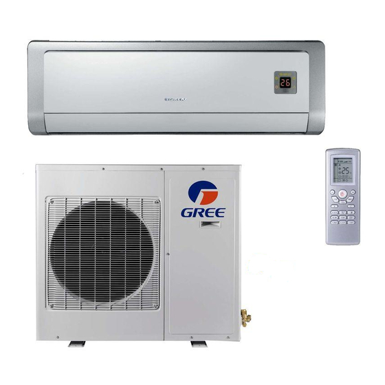
Summary and Features Summary and Features Indoor Unit GWH09AB-A3DNA1B/I GWH12AB-A3DNA1B/I Outdoor Unit GWH09AB-A3DNA1B/O GWH12AB-A3DNA1B/O Remote control window YT1FF MODE I FEEL TIMER CLOCK TIMER X-FAN TEMP TURBO SLEEP LIGHT... -
Page 5: Part 1 Safety Precautions
Safety Precautions 1.Safety Precautions Important! or rubbish. Please Read Before Srarting The unit should be installed according to the instructions This air conditioning system meets strict safety and in order to minimize the risk of damage from earthquakes, operating standards. As the installer or service person, typhoons or strong winds. -
Page 6: Part 2 Specifications
Specifications Specifications Parameter Unit Value Model GWH09AB-A3DNA1B GWH12AB-A3DNA1B Product Code CB11500550 CB11500570 Rated Voltage V ~ Power Rated Frequency Supply Phases Power Supply Mode Outdoor Outdoor Cooling Capacity (Min ~ Max) Btu/h 9000(4000 ~ 11950) 12000(4500 ~ 13000) Heating Capacity (Min ~ Max) Btu/h 9500(3412 ~... - Page 7 Specifications Model of Outdoor Unit GWH09AB-A3DNA1B/O GWH12AB-A3DNA1B/O CHINA CHINA RESOURCES(SHENYANG) RESOURCES(SHENYANG) Compressor Manufacturer/Trademark SANYO COMPRESSOR CO. SANYO COMPRESSOR CO. LTD./SANYO LTD./SANYO Compressor Model C-6RZ110H1A C-6RZ110H1A Compressor Oil FV50S FV50S Compressor Type Rotary Rotary L.R.A. 33.00 Compressor RLA 4.59 4.59 Compressor Power Input...
-
Page 8: Part 3 Construction Views
Constrction Views 3. Construction Views 3.1 Indoor Unit 12K Unit: 3.2 Outdoor Unit Unit:mm Model... -
Page 9: Part 4 Refrigerant System Diagram
Refrigerant System Diagram 4. Refrigerant System Diagram Heat exchanger ( INDOOR ) Muffler 4-Way valve Strainer Expansion valve Heat exchanger Strainer ( OUTDOOR ) Cooling Heating Refrigerant pipe diameter 09K Unit Liquid : 1/4" (6 mm) Gas : 3/8" (9.52 mm) 12K Unit Liquid : 1/4"... -
Page 10: Part 5 Schematic Diagram
Schematic Diagram 5. Schematic Diagram 5.1 Electrical Data Indoor Unit Symbol Color symbol Symbol Color symbol WHITE BROWN YELLOW BLUE BLACK YELLOW GREEN PROTECTIVE EARTH YEGN Outdoor Unit Symbol Parts name Symbol Color symbol WHITE L1 L2 NEUTRAL WIRE, LIVE WIRE YELLOW 4-WAY VALVE ELETRIC EXPANSION VALVE... -
Page 11: Outdoor Unit
Schematic Diagram Outdoor Unit COMP CT1,2 COMP TUBE OUTROOM EXHUAST W8 YEGN TEM.SENSOR TEM.SENSOR TEM.SENSOR W10 RD W3 YEGN W5 BU W6 YE W7 BK OVERHEAT OUTTUBE OUTROOM EXHAUST W15 BU N(1) W4 BK COMU W14 BN FILTER W1 BN W17 RD AC-L1 W2 BU... -
Page 12: Printed Circuit Board
Schematic Diagram 5.3 Printed Circuit Board TOP VIEW high frequency interface of health function live wire indoor fan interface transformer auto button indoor ambient temperature sensor main chip indoor tube temperature sensor BOTTOM VIEW... -
Page 13: Schematic Diagram
Schematic Diagram Models GWH09AB-A3DNA1B/O , GWH12AB-A3DNA1B/O TOP VIEW jumper neutral wire live wire terminal big capacitor electric big capacitor 4-way valve fan terminal jumper 4-way valve terminal expansion valve jumper negative pole positive pole neutral wire terminal live wire neutral wire... -
Page 14: Part 6 Function And Control
Function and Control 6. Function and Control 6.1 Remote Control Operations ON/OFF Button Setpoint Temperature DOWN Button Setpoint Temperature UP Button FAN Speed Button MODE Button I FEEL Button HEALTH function Button AIR function Button Clock Button Timer ON Button X-FAN Button Temperature Displaye Button TIMER OFF Button... - Page 15 Function and Control Auto Medium speed High speed Low speed MODE Press this button, Auto, Cool,Dry, Fan, Heat mode can be selected circularly. Auto mode is default while power on. Under Auto mode, the temperature will not be displayed; In this mode, the unit will automatically select the suitable operation mode in acc- ordance with the room temperature to make the room more comfortable for you.
-
Page 16: Changing Batteries And Notices
Function and Control TEMP : Press this button, could select displaying (the indoor setting temperature) , (indoor ambient temperature )or outdoor am-bient temperature) .The unit defaults not to display the icon. During operation of TEMP button, the set tem- perature is always displayed TIMER OFF Once press this key to enter into TIMER OFF setup, in which case the TIMER OFF icon will blink.The method of setting is the same as TIMER ON. -
Page 17: Description Of Each Control Operation
Function and Control 6.3 Description of Each Control Operation 1. Temperature Parameters Indoor preset temperature (T preset Indoor ambient temperature (T 2. Basic Functions Once energized, in no case should the compressor be restarted within less than 3 minutes. In the situation that memory function is available, for the first energization, if the compressor is at stop before de-energization, the compressor will be started without a 3-minute lag;... - Page 18 Function and Control Protection Protection is the same as that under the cooling mode. (3) Heating Mode Working conditions and process of heating If T Tpreset +2 , the unit enters heating mode, in which case the four-way valve, the compressor and the outdoor fan will amb.
- Page 19 Function and Control Protection In cooling operation, protection is the same as that under the cooling mode; In heating operation, protection is the same as that under the heating mode; When ambient temperature changes, operation mode will be converted preferentially. Once started, the compressor will remain unchanged for at least 6 minutes.
- Page 20 Function and Control 4. Other Controls (1) ON/OFF Press the remote button ON/OFF: the on-off state will be changed once each time you press the button. (2) Mode Selection: Press the remote button MODE, then select and show in the following ways: AUTO, COOL, DRY, FAN, HEAT, AUTO. (3) Temperature Setting Option Button Each time you press the remote button TEMP+ or TEMP-, the setting temperature will be up or down by 1 .
- Page 21 Function and Control (10) Display Operation pattern and mode pattern display All the display patterns will display for a time when the power on, the operation indication pattern will display in red under standby status. When the machine is start by remote control, the indication pattern will light and display the current operation mode (the mode light includes: Cooling, heating and dehumidify).
-
Page 22: Part 7 Installation Manual
Installation Manual 7. Installation Manual 7.1 Notices for Installation 7.1.1 Caution 1.The unit must only be installed by authorized service center according to local or government regulations and in compliance with this manual . 2.Before installating, please contact with local authorized maintenance center. If the unit is not installed by the authorized service center, the malfunction may not be solved due to discommodious contacts. - Page 23 Installation Manual 7.1.5 Safety Precautions for Electric Appliances 1.A dedicated power supply circuit should be used in accordance with local electrical safety regulations. 2.Don’t drag the power cord emphatically. 3.The unit should be reliably earthed and connected to the special earth device by the professionals. 4.The air switch must have the functions of magnetic tripping and heat tripping to prevent short circuit and overload.
-
Page 24: Installation Drawing
Installation Manual 7.2 Installation Drawing Space to the ceiling Above Space to the wall 15cm Above 15cm Above Space to the wall Above Above Space to the floor Air outlet side The dimensions of the space necessary for correct installation of the appliance including the minimum permissible distances to adjacent structures Air inlet side Space to the obstruction... -
Page 25: Install Indoor Unit
Installation Manual 7.3 Install Indoor Unit 7.3.1 Installation of Mounting Plate 1.Make the mounting plate completely level . As the water tray’s oulet of the indoor unit is two-way type, the indoor unit during installation should slightly slant to watert tray’s outlet for smooth drainage of condensing water. 2.Fix the mounting plate on the wall with screws.(Where is pre-covered with plastic granula) 3.Be sure that the mounting plate has been fixed firmly enough to withstand the weight of an adult of 60kg;... - Page 26 Installation Manual 7.3.4 Connecting Indoor and Outdoor Electric Wires 1.Open the front panel. 2.Remove the wiring cover. 3.Make the power connection cord and signal control wire (only for heat Heat PumpType pump unit ) pass through. N(1) 4.Reinstall the cord anchorage and wiring cover. brown yellow- green 5.Reinstall the front panel.the hole at the back of indoor unit.
-
Page 27: Install Outdoor Unit
Installation Manual 7.3.7 Installation of Connection Pipe 1.Align the center of the piping flare with the related valve. 2.Screw in the flare nut by hand and then tighten the nut with spanner and torque wrench by referring to the following: Indoor unit piping Taper nut Piping... -
Page 28: Check After Installation And Operation Test
Installation Manual 7.4.3 Outdoor Condensation Drainage (only for Heat pump unit ) During heating operation, the condensing water and defrosting water should be drained out reliably through the drain hose. Install the outdoor drain connector in a 25 hole on the the base plate and attach the drain hose to the connector, so that the waste water formed in the outdoor unit can be drained out .The hole diameter 25 must be plugged. -
Page 29: Part 8 Exploded Views And Parts List
Exploded Views and Parts list 8. Exploded Views and Parts List 8.1 Indoor Unit... - Page 30 Exploded Views and Parts list Part Code Description GWH09AB-A3DNA1B/I GWH12AB-A3DNA1B/I Product Code CB115N0550 CB115N0570 Front Panel Assy 2000276104 2000276104 Filter Sub-Assy 11122059 11122059 Screw Cover 24252019P 24252019P Front Case 20012049P 20012049P Front Case Assy 20002760 20002760 Guide Louver 10512102 10512102...
-
Page 31: Outdoor Unit
Exploded Views and Parts list 8.2 Outdoor Unit Model GWH09AB-A3DNA1B/O... - Page 32 Exploded Views and Parts list Part Code Description GWH09AB-A3DNA1B/O Product Code CB115W0550 Front Grill 01473012 Cabinet 0143304601P Chassis Sub-assy 01203939P Compressor Gasket 76815203 Drainage Connecter 06123401 Compressor and fittings 00205212 Overload Protector 4300040021 Magnet Coil 4300040021 Discharge sensor 39000016 4-way Valve...
- Page 33 Exploded Views and Parts list Model GWH12AB-A3DNA1B/O 12 13...
- Page 34 Exploded Views and Parts list Part Code Description GWH12AB-A3DNA1B/O Product Code CB115W0570 Front Grill 01473012 Front Panel 0153500201 Chassis Sub-assy 01203939P Compressor Gasket 76815203 Drainage Connecter 06123401 Overload Protector 00180002 Compressor and fittings 00205212 Discharge sensor 39000016 Magnet Coil 4300040021 4-way Valve 430004032 4-way Valve Assy...
-
Page 35: Part 9 Troubleshooting
Troubleshooting 9. Troubleshooting 9.1 Malfunction Analysis Note: When replacing the controller, make sure insert the wire jumper into the new controller, otherwise the unit will display C5 Measure insulation resistance The breaker trips at once when it to ground to see if there is any is set to "ON". - Page 36 Troubleshooting Improper set of temperature Adjust set temperature If cooling (heating) load is Check the forecasted load of cooling (heating) proper Check and fill the leakage, then The refrigerant has leakage vacuumize it and supplement the or is insufficient refrigerant as required Leakage between the high pres- Replace the compressor sure and the low pressure in-...
- Page 37 Troubleshooting The indoor fan motor is burned or breaks Replace the fan motor or the defective part. or has the heat protector malfunction. The built-in heat protector of the motor breaks frequently because the motor is Replace the fan motor The fan does not abnormal.
- Page 38 Troubleshooting C o n t r o l l e r m a l f u n c t i o n ( I C 2 0 0 3 b r o k e n , creepage of Change controller parallel capacitor of relay loop, relay is broken etc.) In cool, heat...
-
Page 39: Flashing Led Of Indoor/Outdoor Unit And Primary Judgement
1.Error codes only can be seen in the type which has the temperature display pcb.maybe some type has not this function,the lamps on the outdoor pcb are avaiable 2.Normally,the communication between indoor unit and outdoor unit is successful, the gree lamp REMARK: (led2)of outdoor pcb blink 1s on, 1s off. - Page 40 Troubleshooting If malfunction occurs,corresponding code will display and the unit will resume normal until protection or malfunction disappears. Yellow indicator blinks for once Compressor stars (normal) Defrosting (normal display of indoor unit) Yellow indicator blinks for twice Anti-freezing protection (normal Yellow indicator blinks for 3 times display of indoor unit) IPM protection...
- Page 41 Troubleshooting Analysis or processing of some of the malfunction display: 1. Compressor discharge protection Possible reasons: shortage of refrigerant; blockage of air filter; poor ventilation or air flow short pass for condenser; the system has noncondensing gas (such as air, water etc.); blockage of capillary assy (including filter); leakage inside four-way valve causes incorrect operation;...
-
Page 42: How To Check Simply The Main Part
Troubleshooting 9.3 How to Check Simply the Main Part (1) Capacitor charge fault (Fault with outdoor unit) (AP1 below refers to the outdoor control panel) Main Check Points: Use AC voltmeter to check if the voltage between terminal L and N on the wiring board is within 210VAC~240VAC. If the reactor (L) is correctly connected? If the connection is loose or fallen? If the reactor (L) is damaged? Fault diagnosis process: Turn on the unit... - Page 43 Troubleshooting (2) IPM Protection, Out-of-step Fault, Compressor Phase Overcurrent (AP1 below refers to the outdoor control panel) Main check points: If the connection between control panel AP1 and compressor COMP is secure? If loose? If the connection is in correct order? If the voltage input of the machine is within normal range? (Use AC voltmeter to measure the voltage between terminal L and N on the wiring board XT) If the compressor coil resistance is normal? If the insulation of compressor coil against the copper tube is in good condition?
- Page 44 Troubleshooting (3)High temperature and overload protection diagnosis (AP1 hereinafter refers to the control board of the outdoor unit) Mainly detect: Is outdoor ambient temperature in normal range? Are the outdoor and indoor fans operating normally? Is the heat dissipation environment inside and outside the unit is good? Fault diagnosis process: Overheat and high temperature protection...
- Page 45 Troubleshooting (4) Start-up failure (following AP1 for outdoor unit control board) Mainly detect: Whether the compressor wiring is connected correct? Is compressor broken? Is time for compressor stopping enough? Fault diagnosis process: Power on the unit Restart it up after Is stop time of the compressor 3 minutes longer than 3 minutes?
- Page 46 Troubleshooting (5) Out of step diagnosis for the compressor (AP1 hereinafter refers to the control board of the outdoor unit) Mainly detect: Whether the system pressure is too high? Whether the input voltage is too low? Fault diagnosis process: Out of step occurs in Out of step occurs once the operation unit is powered on.
- Page 47 Troubleshooting (6)Overload and air exhaust malfunction diagnosis (following AP1 for outdoor unit control board) Mainly detect: Wether the PMV is connected well or not? Is PMV damaged? Is refrigerant leaked? Fault diagnosis process: 20 minutes after the complete unit is powered off Is the terminal FA for the Connect the...
- Page 48 Troubleshooting (7)Power factor correct or (PFC) fault (a fault of outdoor unit) (AP1 hereinafter refers to the control board of the outdoor unit) Mainly detect: Check if the reactor (L) of the outdoor unit and the PFC capacitor are broken Fault diagnosis process: Start Check wiring of the...
- Page 49 Troubleshooting (8) Communication malfunction: (following AP1 for outdoor unit control board) Mainly detect: Is there any damage for the indoor unit mainboard communication circuit? Is communication circuit damaged? Detect the indoor and outdoor units connection wire and indoor and outdoor units inside wiring is connect well or not, if is there any damage? Fault diagnosis process: Start...
- Page 50 Troubleshooting (9) Flow chart for outdoor communitcation circuit detecting: Start Measure voltage at the Test 10 position as shown in the diagram with a voltmeter Value jumping Measure voltage at the Test 15 position as shown in the diagram with a voltmeter Value jumping Fault with outdoor unit...
-
Page 51: Part10 Removal Procedure
Removal Procedure 10. Removal Procedure 10.1 Removal Procedure of Indoor Unit Warning Be sure to wait for a minimum of 10 minutes after turning off all power supplies before disassembly. 1.Remove front panel front Push the convex parts in the left and right sides panel of the front panel, and then lift the front panel. - Page 52 Removal Procedure 5.Remove water tray ground screw electric box cover Unscrew the ground screw on the electric box cover and loose the clasps to remove electric box cover.Pulll out the wiring terminal.Unscrew the 2 screws fixing the water tray to remove the water tray.
- Page 53 Removal Procedure Unscrew the 2 screws in the left of evaporator Turn the evaporator at certain angle to remove it. screw 8.Remove motor and cross flow fan Unscrew the screws fixing the press plate of motor and connecting motor and cross flow fan to remove the motor and cross flow fan.
-
Page 54: Removal Procedure Of Outdoor Unit
Removal Procedure 10.2 Removal Procedure of Outdoor Unit Warning Be sure to wait for a minimum of 10 minutes after turning off all power supplies before disassembly. 1. Remove top cover and handle Remove the screw fixing the handle and then remove the handle;... - Page 55 Removal Procedure 4. Remove electric box sub-assy screw electric box cover Remove the screws fixing the electric box cover and then lift the electric box cover upwards to remove it. Remove the screws fixing the electric box; disconnect the connection wire of compressor with fan motor and electric box, and then lift the electric box upwards to screw remove it.
- Page 56 Removal Procedure 7. Remove 4-way valve assy 4-way valve Unsolder the 4 welding joints of the 4-way valve assy with the condenser, the air-inlet and air-outlet port of welding joint compressor, the gas valve; remove the 4-way valve assy. Unsolder them quickly in order to avoid burning down the leading wire of compressor.
- Page 57 GREE ELECTRIC APPLIANCES,INC.OF ZHUHAI Add:Jinji west Rd.Qianshan Zhuhai Guangdong China Tel:86-756-8522219 (After sale Service Dept) Post code: 5 1 9 07 0...