Advertisement
NOTE:
Please read all instructions
carefully before using this
product
Table of Contents
Safety Notice
Resistance Chart
Model
EVE-1500
Retain This
Manual for
Reference
08-17-05
OWNER'S
MANUAL
CORNER GYM
Made under license from trademark owner Everlast
Worldwide Inc., New York.
14777 DON JULIAN RD., CITY OF INDUSTRY, CA 91746
Tel: (800) 999-8899 Fax: (626) 961-9966
www.impex-fitness.com
info@impex-fitness.com
EVE-1500
IMPEX INC.
Advertisement
Table of Contents

Related Manuals for Everlast EVE-1500


Summary of Contents for Everlast EVE-1500
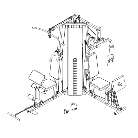
- Page 1 Table of Contents Safety Notice Hardware Pack Assembly Instruction Parts List Resistance Chart Warranty Ordering Parts Model EVE-1500 Retain This Manual for Reference 08-17-05 OWNER'S MANUAL CORNER GYM EVE-1500 Made under license from trademark owner Everlast Worldwide Inc., New York.
-
Page 2: Table Of Contents
BEFORE YOU BEGIN Thank you for selecting the EVERLAST EVE-1500 CORNER GYM by IMPEX INC. For your safety and benefit, read this manual carefully before using the machine. As a manufacturer, we are committed to provide you complete customer satisfaction. If you have any questions, or find there are missing or damaged parts, we guarantee you complete satisfaction through direct assistance from our factory. -
Page 3: Important Safety Notices
OVER THE AGE OF 35 OR PERSONS WITH PRE-EXISTING HEALTH PROBLEMS. READ ALL INSTRUCTIONS BEFORE USING ANY FITNESS EQUIPMENT. IMPEX INC. ASSUMES NO RESPONSIBILITY FOR PERSONAL INJURY OR PROPERTY DAMAGE SUSTAINED BY OR THROUGH THE USE OF THIS PRODUCT. SAVE THESE INSTRUCTIONS. - Page 4 WARNING LABEL REPLACEMENT The warning labels shown here have been placed on the Left Base Frame and Right Upper Frame. If the labels are missing or illegible, please call customer service at 1-800-999-8899 for replacements. Apply the labels in location shown.
-
Page 5: Hardware Pack
HARDWARE PACK... - Page 6 HARDWARE PACK...
- Page 7 HARDWARE PACK...
-
Page 8: Assembly Instructions
ASSEMBLY INSTRUCTION Tools Required Assembling the Machine: Two Adjustable Wrenches and Allen Wrenches. NOTE: It is strongly recommended two or more people assembling this machine to avoid possible injury. STEP 1 (See Diagram 1) A.) Place the Right and Left Base Frames (#1 & #14) on a flat surface. Make sure there is enough space to assemble the machine. - Page 9 STEP 2 (See Diagram 2) A.) Insert two Guide Rods (#12) into the holes on the Guide Rod Base (#10). Secure each Guide Rod with one M10 x ¾” Allen Bolt (#80) and Ø ¾” Washer (#94) from the bottom. B.) Attach the Guide Rod Base to the Left and Right Base Frames (#1 &...
- Page 10 STEP 3 (See Diagram 3) A.) Attach the Right Vertical Beam (#3) onto the Right Base Frame (#1). Secure it with two M10 x 2 ½” Carriage Bolts (#87), Ø ¾” Washers (#94), and M10 Aircraft Nuts (#97). B.) Attach the Left Vertical Beam (#17) onto the Left Base Frame (#14). Secure it with two M10 x 2 ½”...
- Page 11 DIAGRAM 3...
- Page 12 STEP 4 (See Diagram 4) A.) Slide nineteen Weight Plates (#59) onto the Guide Rods (#12). Make sure the grove on the Plates all face toward front of the machine. Insert the Selector Rod (#13) into the center hole. It is strongly recommended to spray lubricant such as WD-40 on the two Guide Rods to minimize friction.
- Page 13 DIAGRAM 4...
- Page 14 STEP 5 (See Diagram 5) A.) Attach the Right Seat Support (#2) onto the Right Base Frame (#1). Secure it with one M10 x 2 ½” Carriage Bolt (#87), Ø ¾” Washer (#94), and M10 Aircraft Nut (#97). B.) Attach the Right Seat Support (#2) to the Right Vertical Beam (#3). Secure it with two M10 x 2 ½”...
- Page 15 STEP 6 (See Diagram 6) A.) Attach the Left Seat Support (#15) to the Left Base Frame (#14). Secure it with one M10 x 2 ½”Carriage Bolts (#87), Ø ¾” Washer (#94), and M10 Aircraft Nut (#97). B.) Attach the Left Seat Support to the Left Vertical Beam (#17). Secure it with two M10 x 2 ½” Carriage Bolts (#87), one 4 3/8”...
- Page 16 STEP 7 (See Diagram 7) A.) Align the Front Press Base (#19) to the Left Upper Frame (#18). Insert a 6” Axle (#52) through the holes and secure it with two Ø ¾” Washers (#94) and M10 Aircraft Nuts (#97). B.) Insert the axle on the Left Butterfly (#20) through the holes on the Front Press Base.
- Page 17 Cable Loop Diagram...
- Page 18 STEP 8 (See Diagram 8 & Cable Loop Diagram) A.) Attach one end of the 118” Butterfly Cable (#42) to the hook on the Right Butterfly (#21). Draw the Cable to the right open Swivel Pulley Bracket (#26). B.) Attach a Pulley (#60) to the Bracket. Secure it with one M10 x 1 ¾” Allen Bolt (#82), two ¾”...
- Page 19 STEP 9 (See Diagram 9 & Cable Loop Diagram) A.) Attach the end of the 115” Front Press Cable (#43) to the open bracket on the Left Vertical Beam (#17). Secure it with one M10 x 1” Allen Bolt (#81), two Ø ¾” Washers (#94), and one M10 Aircraft Nut (#97).
- Page 20 DIAGRAM 9...
- Page 21 STEP 10 (See Diagram 10 & Cable Loop Diagram) A.) Attach the 180” Upper Cable (#40) to the front opening on the Right Upper Frame (#4). B.) Place a Pulley (#60) to the opening and secure it with one M10 x 2 3/8” Allen Bolt (#84), two Pulley Bushings (#78), and one M10 Aircraft Nut (#97).
- Page 22 STEP 11 (See Diagram 11 & Cable Loop Diagram) A.) Attach the 105” Lower Cable (#41) to the opening on the bottom of Leg Developer (#7). B.) Attach a Pulley (#60) to the opening. Secure it with one M10 x 2 3/8” Allen Bolt (#84), two Pulley Bushings (#78), and one M10 Aircraft Nut (#97).
- Page 23 STEP 12 (See Diagram 12 & Cable Loop Diagram) A.) Attach one end of the 276” Leg Press Cable (#44) to the open bracket underneath the Left Seat Support (#15). Secure it with one M10 x 1” Allen Bolt (#81), two Ø ¾” Washers (#94), and one M10 Aircraft Nut (#97).
- Page 24 DIAGRAM 12...
- Page 25 STEP 13 (See Diagram 13) A.) Attach a Backrest Board (#38) to the Right Vertical Beam (#3). Secure it with two M8 x 2 1/8” Allen Bolts (#89) and Ø 5/8” Washers (#93). B.) Attach a Seat Pad (#37) onto the Right Seat Support (#2). Secure it with two M8 x 2 1/8”...
- Page 26 STEP 14 (See Diagram 14) A.) Attach a Backrest Board (#38) to the Left Vertical Beam (#17). Secure it with two M8 x 2 1/8” Allen Bolts (#89) and Ø 5/8” Washers (#93). B.) Attach a Seat Pad (#37) onto the Left Seat Support (#15). Secure it with two M8 x 2 1/8”...
- Page 27 STEP 15 (See Diagram 15) A.) Attach the Weight Stack Cover (#29) to the Guide Rod Upper Frame (#11) and Guide Rod Base (#10). Secure it with four M10 x ¾” Allen Bolts (#80) and Ø ¾” Washers (#94). DIAGRAM 15...
- Page 28 STEP 16 (See Diagram 16) A.) Connect the Lat Bar (#5) to the 180” Upper Cable (#40) with two C-clips (#75) and a Short Chain (#74). Store the Lat Bar onto the hooks on the Right Upper Frame. B.) Connect the Abdominal Strap (#99) to the Cable Head Connector (#45) with a C-clip. Secure the C-clip to the Connector with one M10 x 1 1/8”...
-
Page 29: Parts List
PARTS LIST KEY NO. DESCRIPTION Right Base Frame Right Seat Support Right Vertical Beam Right Upper Frame Lat Bar Arm Curl Stand Leg Developer Arm Curl Handle Rear Vertical Beam Guide Rod Base Guide Rod Upper Frame Guide Rod Selector Rod Left Base Frame Left Seat Support Leg Press Frame... -
Page 30: Resistance Chart
EVE-1500 Weight Resistance Chart WEIGHT FRONT PLATE PRESS PULLEY *Each plate weights approximately 10 lbs. *Resistance measured in pounds. *Numbers are approximate. Actual number may vary. BUTTERFLY STATION STATION PRESS... -
Page 31: Warranty
IMPEX Customer Service Department at 1-800-999-8899. All freights on products returned to IMPEX must be prepaid by the customer. This warranty does not extend to any product or damage to a product caused by or attributable to freight damage, abuse, misuse, improper or abnormal usage or repairs not provided by an IMPEX authorized service center or for products used for commercial or rental purposes.