Table of Contents
Advertisement
Quick Links
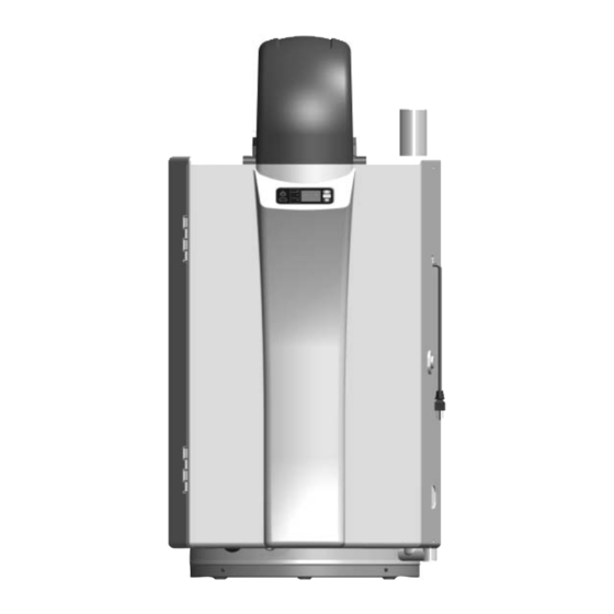
Installation and Operating Manual
HYBRID GAS WATER HEATERS
POWER VENT GAS MODELS
www.hotwater.com
ANSI Z21.10.3b-2008
•
•
For Your Safety
AN ODORANT IS ADDED TO THE GAS USED
BY THIS WATER HEATER.
ALL TECHNICAL AND WARRANTY QUESTIONS: SHOULD BE DIRECTED TO THE LOCAL DEALER FROM WHOM THE WATER HEATER WAS
PURCHASED.
KEEP THIS MANUAL IN THE POCKET ON HEATER FOR FUTURE REFERENCE
WHENEVER MAINTENANCE ADJUSTMENT OR SERVICE IS REQUIRED.
1010
319995-000
Advertisement
Table of Contents

Related Manuals for A.O. Smith Power Vent Gas Series


Summary of Contents for A.O. Smith Power Vent Gas Series
-
Page 1: For Your Safety
Installation and Operating Manual HYBRID GAS WATER HEATERS POWER VENT GAS MODELS www.hotwater.com ANSI Z21.10.3b-2008 • • For Your Safety AN ODORANT IS ADDED TO THE GAS USED BY THIS WATER HEATER. ALL TECHNICAL AND WARRANTY QUESTIONS: SHOULD BE DIRECTED TO THE LOCAL DEALER FROM WHOM THE WATER HEATER WAS PURCHASED. -
Page 2: Table Of Contents
TABLE OF CONTENTS SAFE INSTALLATION, USE AND SERVICE OPERATING INSTRUCTIONS GENERAL SAFETY Display Panel ......33 INTRODUCTION Wiring Diagram . -
Page 3: Safe Installation, Use And Service
SAFE INSTALLATION, USE AND SERVICE Your safety and the safety of others is extremely important in the installation, use and servicing of this water heater. Many safety-related messages and instructions have been provided in this manual and on your own water heater to warn you and others of a potential injury hazard. -
Page 4: General Safety
GENERAL SAFETY www.hotwater.com... - Page 5 GENERAL SAFETY DANGER WARNING Breathing Hazard - Carbon Monoxide Gas • Install vent system In accordance with codes. • Do not operate water heater if flood damaged. • Special Consideration must be taken with installations above 11,000' (3,352m) for standard models.
-
Page 6: Introduction
INTRODUCTION Thank You for purchasing this water heater. Properly Carefully plan the place where you are going to put installed and maintained, it should give you years of trouble the water heater. Correct combustion, vent action, and free service. vent pipe installation are very important in preventing Abbreviations Found In This Instruction Manual: death from possible carbon monoxide poisoning and •... - Page 7 www.hotwater.com...
-
Page 8: Get To Know Your Water Heater - Gas Models
GET TO KNOW YOUR WATER HEATER - GAS MODELS A Mixing Valve*** U Side Casing (Plastic) B Hot Water Outlet (Tempered)*** V Top Casing Enclosure (Plastic) C Pipe Insulation*** W Exhaust Elbow Assembly D Inlet Water Shutoff Valve*** X T&P Relief Valve E Cold Water Inlet*** Y Anode F Expansion Tank***... -
Page 9: Installation Considerations
INSTALLATION CONSIDERATIONS ROUGH IN DIMENSIONS Top View Left Side View FIGURE 2 Capacity, Gas and Electrical Characteristics Model Approx. Capacity Input Gas Supply Pressure Manifold Pressure Electrical Characteristics Type U.S. Gals. Litres BTU/hr Max. Min. in. WC (kPa) Volts/Hz Amperes in. - Page 10 INSTALLATION REQUIREMENTS FOR THE COMMONWEALTH OF MASSACHUSETTS For all side wall terminated, horizontally vented power vent, gas fueled water heaters installed in every dwelling, building or structure used in whole or in part for residential purposes, including those owned or operated by the Commonwealth and where the side wall exhaust vent termination is less than seven (7) feet above finished grade in the area of the venting, including but not limited to decks and porches, the following requirements shall be satisfied: INSTALLATION OF CARBON MONOXIDE DETECTORS At the time of installation of the side wall horizontal vented gas fueled...
-
Page 11: Water Piping - Mixing Valve Usage
WATER PIPING - MIXING VALVE USAGE SUGGESTED PIPING ARRANGEMENT FOR TOP CONNECTIONS TEMPERED SHUT-OFF VALVE POTABLE WATER TEMPERED POTABLE WATER COLD WATER INLET THERMAL EXPANSION TANK TEMPERATURE- PRESSURE RELIEF VALVE MIXING DISCHARGE VALVE PIPE (DO NOT (OPTIONAL) CAP OR PLUG) PIPE INSULATION (RECOMMENDED) METAL... -
Page 12: Facts To Consider About Location
and the physically or developmentally disabled. If anyone Important: The electrical controls used inside the gas using hot water from this heater fi ts into one of these control of this water heater are polarity sensitive. Ensure groups or if there is a local code or state law requiring a the electrical supply is connected correctly in the receptacle certain temperature water at the hot water tap, then you box. -
Page 13: Handle Installation
Also, the water heater must be located and/or protected so DANGER it is not subject to physical damage by a moving vehicle. FLAMMBLE Flammable Vapors Vapors from flammable Water heater has a main liquids may explode and burner and spark generator. catch fire causing death or The spark generator: severe burns. -
Page 14: Earthquake Zones
When installing the heater, consideration must be given to Remove the right side panel proper location. Location selected should be as close to Use a screwdriver to remove the screw from the the wall as practicable and as centralized with the water bottom, front of the right side panel. - Page 15 Screws Screws Casing (Front) FIGURE 7 Screws FIGURE 9 After the heater has been positioned and the earthquake straps have been installed, re-assemble the shroud in the reverse order. FIGURE 8 www.hotwater.com...
-
Page 16: Combustion Air And Ventilation
COMBUSTION AIR AND VENTILATION In unconfi ned spaces in buildings, infi ltration may be adequate to provide air for combustion, ventilation and A gas water heater cannot operate properly without the dilution of flue gases. However, in buildings of tight correct amount of air for combustion. -
Page 17: Opening Should Have A Minimum Free Area Of 1 Square
FIGURE 11 FIGURE 13 B. ALL AIR FROM OUTDOORS: (See Figures 12, 13 and 4. When ducts are used, they should be of the same cross-sectional area as the free area of the openings to The confi ned space should be provided with two permanent which they connect. -
Page 18: Chemical Vapor Corrosion
6. Louvers and Grilles: In calculating free area, Water heaters are intended to produce hot water. Water consideration should be given to the blocking effect of heated to a temperature which will satisfy space heating, louvers, grilles or screens protecting openings. Screens clothes washing, dish washing, cleaning and other sanitizing used should not be smaller than 1/4 in. -
Page 19: Hard Water
limited warranty. Thermal expansion can also cause HARD WATER intermittent temperature-pressure relief valve operation: We highly recommend installing water fi ltering system or water discharged from the valve due to excessive pressure a water softener before the water heater system. If you build up. -
Page 20: Figure 17
The temperature-pressure relief valve must be installed The temperature-pressure relief valve must be manually directly into the fi tting of the water heater designed for the operated at least once a year, (see Figure 17). Caution relief valve. Must terminate a maximum of 6 in. (15cm) should be taken to ensure that (1) no one is in front of or above a fl... -
Page 21: Gas Piping
GAS PIPING Use pipe joint compound or Tefl on tape marked as being resistant to the action of petroleum [Propane (L.P.)] Make sure gas supplied is same type listed on model gases. rating plate. The inlet gas pressure must not exceed 14 in. -
Page 22: Gas Line Purging
a sediment trap) must be incorporated in the piping. The FLOODING/FREEZING drip leg must be readily accessible. Install in accordance with the “Gas Piping” section. Refer to the current edition If this water heater has been exposed to flooding, of the National Fuel Gas Code (ANSI Z223.1/NFPA 54). freezing, fi... -
Page 23: Vent Pipe Termination
VENT PIPE TERMINATION Instructions on proper installation through a sidewall are provided in Figures 31. NOT RECOMMENDED: PREFERRED PRACTICE: Plan the vent system layout so that proper clearances are maintained from plumbing and wiring. Vent pipes serving power vented appliances are classifi ed by building codes as “vent connectors”. - Page 24 NOTE: VENT PIPE MUST BE SUPPORTED EVERY 4 ft. (1.2m). TO PREVENT VIBRATION, USE ISOLATION PADS WHEN ATTACHING STRAPS TO FLOOR JOISTS, WALLS OR CEILINGS. TERMINATION 45° ELBOW ELBOW STRAP 90° ELBOW RODENT SCREEN (INSTALL INTO Example for calculating equivalent feet. Vent piping must slope up ELBOW) Section “A”...
-
Page 25: Condensate
CONDENSATE VENTING EXHAUST ELBOW This water heater is a condensing unit and requires a drain BARBED FITTING to be located in close proximity to allow the condensate to drain safely. The condensate drains from the unit at CONDENSATE the exhaust tee located at the bottom of the unit (see TRAP Figure 22). -
Page 26: Sequence Of Installations
SEQUENCE OF INSTALLATIONS B. WOODEN SIDE WALLS Drill a pilot hole Cut a length of PVC pipe about 3.5 in. (9cm) longer than approximately 1/4 in. (0.64cm) outside of the marked the wall thickness at the opening. Glue the vent terminal circle. -
Page 27: Installation Of Vent System, Sidewall
ATTACH 45° BRACKET 6 in. (15 cm) TERMINATION MIN. LENGTH ELBOW SEALANT ATTACH 45° TERMINATION ELBOW RODENT EQUIVALENT SCREEN VENT LENGTH VENT PIPING TO BE (INSTALL MEASURED SLOPED (DOWN) RODENT INTO FROM THIS TOWARD HEATER SCREEN ELBOW) POSITION TO PREVENT WATER (INSTALL SEALANT FROM COLLECTING. -
Page 28: Vent Pipe Preparation
VENT PIPE PREPARATION 1. INITIAL PREPARATION. A. Make sure the solvent cement you are planning to use is designed for the specifi c application you are attempting. B. Know the physical and chemical characteristics and limitations of the PVC and CPVC piping materials that you are about to use. - Page 29 *USE ONLY NATURAL BRISTLE 3. MAKING THE JOINT. A. Cutting Pipe must be squarely cut to allow for the proper interfacing of the pipe end and the fi tting socket bottom. This can be accomplished with a miter box saw or wheel type cutter Wheel type cutters are not generally recommended for larger diameters since they tend to fl...
-
Page 30: Connection To Vent Pipe
D. Inspection, cleaning, priming G. Cleanup and joint movement Visually inspect the inside of the pipe and fi tting Remove all excess cement from around the pipe sockets and remove all dirt, grease or moisture and fi tting with a dry cotton rag. This must be done with a clean dry rag. -
Page 31: U.s. Power Vent
U.S. POWER VENT WARNING VENT HOOD(S) MAY BE EXTREMELY HOT DURING OPERATION. FIGURE 31 CAUTION TO PREVENT EXHAUSTING PRODUCTS FROM CIRCULATING TO THE AIR INTAKE IN WINDY/COLD AREAS, THE MAXIMUM PRACTICAL DISTANCE BETWEEN THESE TWO TERMINALS IS RECOMMENDED. www.hotwater.com... -
Page 32: Electrical Connections
ELECTRICAL CONNECTIONS To put the heater into service after a successful calibration: The water heater must be connected to a properly Unplug the power cord from the 120Vac/60Hz outlet grounded electrical branch circuit. A dedicated circuit is Open (plastic) front door of the heater and remove the preferred. -
Page 33: Operating Instructions
OPERATING INSTRUCTIONS DISPLAY PANEL STANDBY LED TEMPERATURE (GREEN) UNITS-OF-MEASURE STANDBY-ON/OFF NUMERIC UP (HOTTER) BUTTON DISPLAY BUTTON MODE BUTTON BURNER IN KEY LOCK OPERATION MODE LEDs (3) DOWN (COLDER) FAULT INDICATOR BUTTON FIGURE 33 Changing the Standby Status Operating Modes When the Standby Button is pressed, the Status changes Operating modes are: to normal operation and all the LEDs on the display will Boost (for peak demand), Energy Saver and Vacation. - Page 34 Numeric Display Burner in Operation Numeric information such as temperature set-point, When the burners are in operation and fl ame is detected maintenance codes and error codes are displayed using by the fl ame sensor, the fl ame symbol is illuminated. a large yellow LED display.
-
Page 35: Wiring Diagram
WIRING DIAGRAM FIGURE 34 www.hotwater.com... -
Page 36: Lighting Instructions
LIGHTING INSTRUCTIONS FOR YOUR SAFETY READ BEFORE LIGHTING FLAMMABLE BEFORE LIGHTING: ENTIRE SYSTEM MUST BE FILLED WITH WATER AND AIR PURGED FROM ALL LINES A. This appliance does not have a pilot. It is equipped with • If you cannot reach your gas supplier, call the fire an ignition device which automatically lights the burner. -
Page 37: Heat Cycle Defi Nitions
HEAT CYCLE DEFINITIONS STATE DESCRIPTION Pre-purge If the heat engine initial call-for-heat is successful (all checks are passed), the combustion fan is energized. The fan is started at a high speed for several seconds and the system verifi es the fan speed. -
Page 38: Temperature Regulation
TEMPERATURE REGULATION THIS WATER HEATER IS EQUIPPED WITH AN ADJUSTABLE THERMOSTAT TO CONTROL WATER TEMPERATURE. HOT WATER TEMPERATURES REQUIRED FOR AUTOMATIC DISHWASHER AND LAUNDRY USE CAN CAUSE SCALD BURNS RESULTING IN SERIOUS PERSONAL INJURY AND/OR DEATH. THE TEMPERATURE AT WHICH INJURY OCCURS VARIES WITH THE PERSON’S AGE AND THE TIME OF THE EXPOSURE. -
Page 39: Unique Hybrid Features
Three LED’s are used to indicate the Operating Mode Time for Time for 1st Selection Permanent Burns Water Degree Burn Vacation Mode: Yellow LED 2nd & 3rd Degree Temperature (Less Severe Energy Saver Mode: Green LED (Most Severe Burns) Boost Mode: Orange LED Burns) 110°F (44°C) - Page 40 Water Circulation Pump The power for the main gas valve is to be routed through A circulation pump is integrated into the heat engine for the Exhaust Vent High Temperature Switch causing the the Hybrid application. The pump serves to push water main gas valve to be de-energized immediately when the through the heat engine at a rate that supports optimum switch opens.
-
Page 41: Temperature Regulation
Line Voltage Monitor Storage Tank Call For Heat The control monitors the line voltage provided to The storage tank call for heat is generated when the tank the system. If the line voltage is too low, the system thermistor temperature drops below the storage tank set- components may not operate properly. -
Page 42: Constant Output Temperature Control
CONSTANT OUTPUT TEMPERATURE CONTROL OPERATIONAL CONDITIONS While the temperature regulation in the previous section Smelly Water describes the features of temperature monitoring and In each water heater there is installed at least one anode regulation, your water heater goes beyond the on/off rod (see parts section) for corrosion protection of the tank. -
Page 43: Maintenance
MAINTENANCE HOUSEKEEPING Vacuum around base of water heater for dust, dirt, and lint on a regular basis. VENTING SYSTEM INSPECTION At least once a year a visual inspection should be made of the venting system. You should look for: Obstructions which could cause improper venting. The combustion and ventilation air fl... -
Page 44: Anode Rod Replacement
softened water is exceedingly corrosive because the TEMPERATURE-PRESSURE RELIEF VALVE process substitutes sodium ions for magnesium and OPERATION calcium ions. The use of a water softener may decrease the life of the water heater tank. The anode rod should be inspected after 3 years of use and annually thereafter until the condition of the anode rod dictates its replacement. -
Page 45: Snow Accumulation
SNOW ACCUMULATION Heat Keep the area around fl ue terminal free of snow and ice. Engine The appliance will not function properly if the intake air Cabinet or exhaust is impeded (blocked or partially blocked) by obstructions. Water CLEANING THE INLET WATER FILTER Inlet Filter The cold water inlet fi... -
Page 46: Draining The Tank
• Disconnect the hoses joining the tank and the heat • Reconnect the original hoses to the tank. engine (upper hose is water outlet and lower hose is • Remove the in-line fi lter at the cold water inlet and water inlet). -
Page 47: Diagnostic Display
DIAGNOSTIC DISPLAY By simultaneously pressing the “Mode” and “down arrow” buttons for 3 seconds the unit will allow access to the diagnostic mode. In diagnostic mode, using the up/down arrow allows for cycling between diagnostic codes. The numeric display will show the diagnostic code for 1 second, followed by the actual measurement displayed for 3 seconds. - Page 48 If an error code is displayed, or odd behavior of the unit occurs, the fi rst corrective action should be to “Cycle the Power”: Unplug the 120Vac power cord and after 5 seconds plug it in again. If this doesn’t clear the fault, proceed with the “Remedy”...
- Page 49 Fault Lockout Code Description Cause Remedy type Displayed Blower speed is 200RPM below the target speed for 20 seconds. Blower speed is 500RPM above the target speed for 6 seconds. Soft Check the blower wire harness. Blower speed Machine starts or normal Change the blower.
- Page 50 Fault Lockout Code Description Cause Remedy type Displayed Water Flow Valve The water valve did not Check the water valve wire harness. Closed. open when attempting to Soft Change the board. establish fl ow. Change the water valve. Proportional Valve The closed loop control Check the proportional gas valve wire (PV) Response...
-
Page 51: Troubleshooting
TROUBLESHOOTING These guidelines should be utilized by a qualifi ed service agent. Problem Possible Cause(s) What to do NOT ENOUGH HOT WATER STANDBY button turned off. Press switch to turn heater on. No power at outlet. Repair service to outlet. Error Code being displayed Refer to “FAULT INDICATION AND ERROR CODES”... - Page 52 Problem Possible Cause(s) What to do WHEN THE TAP IS OPENED, a. The hot water fi xture is not Check if there is any error code on THERE IS NO HOT WATER OR THE suffi ciently open to draw the water the display.
-
Page 53: Service
SERVICE If a condition persists or you are uncertain about the operation of the water heater contact a qualifi ed service agency. LEAKAGE CHECKPOINTS Use this guide to check a “Leaking” water heater. Many suspected “Leakers” are not leaking tanks. Often the source of the water can be found and corrected. -
Page 54: Parts Identifi Cation
PARTS IDENTIFICATION ITEM # DESCRIPTION Baffl e, Flue Hot Water Outlet Nipple (w/ Anode, Heat Trap) T&P Relief Valve Cold Water Inlet Nipple (w/ Dip Tube, Heat Trap) Cover, Back-Flue Gas Return Top Insulation Flue Gas Return Duct Assy Shroud, Back-Tank Assembly Shroud, Right Side-Tank Assembly Temperature Switch Condensate Trap... - Page 55 www.hotwater.com...
-
Page 56: Replacement Parts
REPLACEMENT PARTS DESCRIPTION KIT # Drain valve 9000058015 T&P relief valve 9003741005 Anode/MG/NIP/HT 9004333005 Anode/AL/NIP/HT 9006291005 Circulation pump assembly 9007173005 Inlet/outlet thermistor (Temp sensor) 9007174005 PCB assembly w/ base 9007175005 12” Hose (braided) 9007176005 Tank thermistor 9007177005 NIP/DIP/TBO/HT 9007178005 Hi limit 85 (ECO) 9007179015 Drain/trap assembly-condensate 9007205005... -
Page 57: Limited Residential Gas Warranty
LIMITED RESIDENTIAL GAS WARRANTY THIS WARRANTY IS APPLICABLE TO THE ORIGINAL OWNER ONLY If SERVICE AND LABOR RESPONSIBILITY the glass lined tank in this water heater shall prove upon examination by (the UNDER THIS LIMITED WARRANTY, THE WARRANTOR WILL warrantor) to have leaked during the warranty period in normal residential PROVIDE ONLY A REPLACEMENT WATER HEATER OR PART use, due to natural corrosion from potable water therein, the warrantor will THEREOF. -
Page 58: Notes
NOTES www.hotwater.com... - Page 59 NOTES www.hotwater.com...
- Page 60 500 TENNESSEE WALTZ PARKWAY ASHLAND CITY, TN 37015 PHONE: 1-800-433-2545 FAX: 1-800-433-2515 www.aosmithwaterheaters.com / email: parts@hotwater.com...