GE Profile WPGT9150 Technical Service Manual
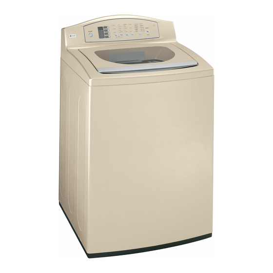
High-efficiency washer
Hide thumbs
Also See for Profile WPGT9150:
- Owner's manual and installation instructions (44 pages) ,
- Owner's manual and installation instructions (44 pages) ,
- Service manual (18 pages)

Related Manuals for GE Profile WPGT9150


Summary of Contents for GE Profile WPGT9150
- Page 1 GE Consumer & Industrial Technical Service Guide June 2008 GE Profi le High-Effi ciency Washer WPGT9150 31-9171 GE Appliances General Electric Company Louisville, Kentucky 40225...
- Page 2 If grounding wires, screws, straps, clips, nuts, or washers used to complete a path to ground are removed for service, they must be returned to their original position and properly fastened. GE Consumer Products Technical Service Guide Copyright © 2008 All rights reserved.
-
Page 3: Table Of Contents
Table of Contents Backsplash ...................................15 Basic Wash Cycle ................................9 Bearing Housing Assembly ............................30 Brake Resistor ..................................17 Clutch Shifter Assembly ..............................28 Component Locator Views ............................12 Component Logic Flow Chart .............................31 Control Features ................................6 Control System ..................................15 Drain Pump ..................................22 Error Codes ..................................35 Introduction .................................. -
Page 4: Nomenclature
Nomenclature Model Number W P G T 9 1 5 0 H 0 W W Back Splash GE Washer Color Feature Pack Body Color Common Brand Features Exceptions: Engr. Revision H = Energy Star P = Profi le™ Model Year... -
Page 5: Introduction
Introduction General The GE Profi le High-Effi ciency Washer is part of the GE Profi le Clothes Care system utilizing the latest developments in washing technology. The Profi le High-Effi ciency Washer does not use the typical agitator found on conventional washers. -
Page 6: Control Features
Control Features Throughout this manual, features and appearances may vary from your model. Power Press to “wake up” the display. If the display is active, press to put the washer into idle mode. Note: Pressing POWER does not disconnect the appliance from the power supply. Wash Cycles The wash cycles are optimized for specifi... - Page 7 WASHABLE WOOL For the washing of machine washable wool products, provided that they are washed according to the instructions on the garment label. When selecting this cycle, you must use a detergent suitable for washing wool. _____________________________________________________________________________________ MY CYCLE Press to use, create or modify custom wash cycles. _____________________________________________________________________________________ SPEED WASH For lightly soiled items that are needed in a hurry.
-
Page 8: Washer Features
Washer Features Cycle Signal Use the SIGNAL button to change the volume of the end of cycle signal. Press the button until you reach the desired volume. _________________________________________________________________________________________ Soak SOAK is an extra wash before the main wash. Use it for heavily soiled clothes or for clothes with a care label that recommends soaking before washing. -
Page 9: Basic Wash Cycle
Operation Overview Note: Dry load and wet load sensing are used on all Basic Wash Cycle cycles except COMFORTERS. Note: See for identifi cation Component Locator Views COMFORTERS cycle defaults to the maximum water and location of washer components. level. After a load is placed in the basket, the user selects Wash Water Temperature the appropriate wash cycle and presses start. - Page 10 Centrifusion Wash Conditioning Spin The locked infusor and wash basket begin a The infusor and wash basket lock together. The clockwise spin (fi gure 1). The speed of the spin is basket spins very slowly at fi rst. This allows dirty customized to the load type and fabric type.
-
Page 11: Wash Cycle Chart Example
Wash Cycle Chart Example User Selection of Cycle Dry Load Sensing Water Fill Adjust Water Temp Wet Load Sensing Adjust Water Fill (only if needed) Wash Process Basket Wash Centrifusion Wash Infusor Wash Spin and Drain* *Spin Information Spray Rinse Maximum spin speeds will vary depending on the cycle: Hand-wash 500 rpm... -
Page 12: Component Locator Views
Component Locator Views Balance Ring 304 Stainless Wash Basket Infusor Tub Cover Pressure Sensor Hose Suspension Rod Motor Wiring Harness Drain Pump (Continued Next Page) – 12 –... - Page 13 Note: To view the basket while it is in operation, open the lid Lid Switch and place a magnet on the left front corner of the top cover (in front of the bleach dispenser). Bleach Water Reservoir Additive Dispenser Pressure Sensor Magnet Underside of Top Cover Backsplash...
-
Page 14: Inverter And Main Board Pin Connectors
Inverter and Main Board Pin Connectors Inverter Board Lid Switch Pressure Sensor Hall Sensor Main Board CON1 Main Board CON2 Thermistor Water Valve Assembly Washer Motor Power LED Clutch Motor Drain Pump 120 VAC Input From RF Choke Brake Resistor Ground Main Board Cable 2 to CON1... -
Page 15: Backsplash
Washer Components Control System Backsplash The washer control system consists of two main The backsplash must be removed to access the components: control system components. • Main PCB To remove the backsplash: • Inverter PCB Remove the 4 Phillips-head screws that hold the backsplash in place. -
Page 16: Inverter
Testing the Inverter Inverter The inverter board is enclosed in a protective box mounted on the top cover under the backsplash. CON2 To access and remove the inverter: Remove backsplash. (See Backsplash Power LED Remove the 2 Phillips-head screws that hold the inverter box in place. -
Page 17: Brake Resistor
• When the washer is turned on by pressing a Brake Resistor membrane pad, the Power LED on the inverter comes on. • The brake resistor absorbs energy from the reversing of the motor during the brake cycle. • When the Power LED is on, the 12-VDC power supply on the inverter board is energized and •... -
Page 18: Pressure Sensor (Water Level Switch)
The frequency is monitored by the inverter, which Pressure Sensor (Water Level Switch) turns off the water valves when the desired water level is achieved. The pressure sensor is connected by a clear hose to an air reservoir near the bottom of the outer tub and Note: The water level will vary depending on the operates by a frequency (kHz) signal to the inverter load size, which is measured by the dry load and... -
Page 19: Water Valve Assembly
To remove the pressure sensor: Water Valve Assembly Remove the backsplash. (See Backsplash The water valve consists of a valve body and fi ve Disconnect the wiring harness from the pressure solenoid coils. It is only available as a complete sensor. -
Page 20: Top Cover
2. Note the placement of the wires, then 6. Remove the water valve assembly and disconnect the wiring from the solenoid coils. distribution pipe. Note: The distribution pipe separates from the water valve assembly as shown below. Disconnect 3. Squeeze the clamps on the 2 water inlet hoses and slide back. -
Page 21: Wash Basket
3. Disconnect the pressure sensor hose from the Wash Basket outer tub. Caution: If the basket is not free to rotate, damage to the clutch coupler can occur. Ensure that the washer is in the spin mode before removing the wash basket. -
Page 22: Drain Pump
4. Remove the 10-mm hex-head screw that holds Drain Pump the infusor in place with a socket or Phillips- head screwdriver (turn screw counterclockwise • The drain pump consists of a 120 VAC, 60-Hz, to remove). motor, impeller, and impeller housing. Note: The 10-mm screw has a rubber O-ring. - Page 23 2. Remove the 4 Phillips-head screws (2 on each To remove the drain pump: side) that hold the back cover in place. Remove Note: Water will remain in the hoses even when the back cover. the tub appears empty. Use care to avoid water spills.
-
Page 24: Thermistor/Atc Control (Auto Temp)
5. Remove the 2 Phillips-head screws that hold the Thermistor/ATC Control (Auto Temp) drain pump mounting plate to the washer fl oor. • The ATC control uses a water temperature sensor (thermistor) to regulate the wash water temperature. • The thermistor has a negative temperature coeffi... -
Page 25: Outer Tub And Suspension Assembly
Resistance can be measured at the purple 2-pin Outer Tub and Suspension Assembly connector on the inverter board. Make sure to unplug the connector to isolate the thermistor The wash basket, outer tub, and motor are before taking resistance readings. (See Inverter and suspended by four rod and spring assemblies. -
Page 26: Motor Assembly
3. Lift the outer tub up and disengage the The washer motor has an approximate resistance value of 8 Ω between any two of the three wires: suspension rod assemblies from each corner of the outer tub. Ω • Blue to red - 8 Ω... - Page 27 Hall Sensor To remove the rotor and stator: • The Hall effect sensor measures the motor rpm. WARNING: The rotor is not grounded. Unplug the washer before servicing to avoid electrical shock. • Four wires connect the Hall sensor to the inverter board at the 4-pin dark blue connector.
-
Page 28: Clutch Shifter Assembly
5. Disconnect the wiring harnesses from the stator Clutch Shifter Assembly and the Hall sensor. The clutch assembly locks or unlocks the basket IMPORTANT: The motor connector and Hall sensor and infusor together, depending on the wash cycle connector are very fragile, handle with care. pattern. - Page 29 Clutch Operation To diagnose the clutch motor: • The clutch locks and unlocks the basket by • The inverter supplies 120 VAC to the clutch engaging teeth on the inside of the rotor with motor through the brown and white wires when teeth on the clutch coupler.
-
Page 30: Bearing Housing Assembly
To remove the clutch shifter assembly: Bearing Housing Assembly Remove the rotor. (See Motor Assembly. To remove the bearing housing assembly: Remove the three Phillips-head screws from the Remove the motor assembly and clutch shifter clutch coupler plate. assembly. (See Motor Assembly Clutch Shifter Assembly... -
Page 31: Component Logic Flow Chart
Component Logic Flow Chart Control Panel INPUTS INPUTS Pressure Clutch Brake Hall Sensor Thermistor Sensor Motor Switch Resistor PROCESSING INVERTER PROCESSING Motor Water Valve Drain Pump OUTPUTS – 31 –... -
Page 32: Test Mode
Troubleshooting Test Mode The dryer control has a service test mode that can be utilized by the service technician in order to test critical components and to access error codes. This test mode will help the service technician to quickly identify failed or improperly operating dryer components. - Page 33 Test Mode Displays • The display will initially show “t1”. • Press the START button. Once the START button is pushed, the display will initially toggle between “t1” and H3”. All LEDs turn on. This cycle will continue until the START button or CYCLE button is pressed.
- Page 34 Test Mode Displays • The display will initially show “t5”. • Press the START button. Once the START button is pushed, the display will initially toggle between “t5” and the estimated agitate RPM. The control will enable agitation and remain there for a maximum of 3 minutes (or until the CYCLE or START button is pressed).
-
Page 35: Error Codes
Error Codes Error Description Code Overfl ow Error Critical Inverter Not Operating Correctly Critical Inlet Valve Failure Critical Pump Failure Critical Clutch Error Critical Pressure Sensor Failure Critical Lid Switch Failure Critical EEPROM Error Control Inoperable Motor Not Rotating Properly Critical No Brake Resistance Critical... - Page 36 Problem Possible Cause What To Do Control panel is asleep • This is normal. Press POWER. Washer won’t operate Washer is unplugged • Make sure cord is plugged securely into a working outlet. Water supply is turned off • Turn both hot and cold faucets fully on. Controls are not set properly •...
- Page 37 – 37 –...
-
Page 38: Schematic
Schematic – 38 –... -
Page 39: Warranty
This warranty is extended to the original purchaser and any succeeding owner for products purchased for home use within the USA. If the product is located in an area where service by a GE Authorized Servicer is not available, you may be responsible for a trip charge or you may be required to bring the product to an Authorized GE Service location for service.