
Related Manuals for Daewoo D-CV701PC Series


Summary of Contents for Daewoo D-CV701PC Series
- Page 1 Service Manual Wall-Mounted Front-Load Washer MINI D-CV701PC** D-CV701AW** D-CV701AW**01...
-
Page 2: Table Of Contents
1. What is Wall-Mounted Front-Load Washer MINI? ..........2 2. Specifications ......................4 3. Assembly Part List ....................5 4. PCB Functions ....................14 5. Wiring Diagram ....................29 6. Part List and Major Specifications ..............30 7. Installation ......................47... -
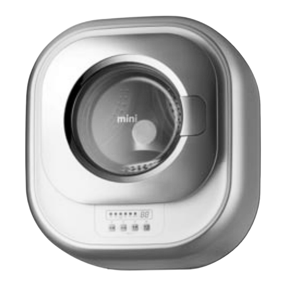
Page 3: What Is Wall-Mounted Front-Load Washer Mini
1. What is Wall-Mounted Front Load Washer MINI? 1. What is the Wall-Mounted Front-Load Washer MINI? Mini is the world's first ever wall-mounted front-load washer, which is installable in bathroom, pantry, kitchen and various locations. 2. Features of Wall-Mounted Front-Load Washer MINI Spoon-Shaped Detergent Container Containers for detergent and softener are discretely designed to prevent... - Page 4 As the Normal cycle takes only 29 minutes, it speeds up the laundry process and reduces water and power consumption by 64% compared to regular front-load washers. 3. Baby Clothes Cleaning (D-CV701PC**, D-CV701AW**) Mini's 'Baby Care' cycle enables a complete steam wash and rinse function to protect sensitive baby skin from irritation.
-
Page 5: Specifications
DOOR FRAME *O BODY COVER Category Specifications Notes Dimension 550mmX600mmX292mm(WXHXD) Weight 16.5KG Standard Volume Power 220V, 50/60Hz Power Wash 100W D-CV701PC**/701AW**/701AW**01 Consumption Steam 1500W D-CV701PC**/AW** Standard Wash Load Spin Washer Type Front Load Installation Mounted on Wall Water Pressure 98.1KPA~784KPA (1KGf/cm2~8KGf/CM2) -
Page 6: Assembly Part List
3. Assembly Part List 1. TUB AS... - Page 7 PART NAME PART CODE DESCRIPTION Q’TY REMARK DRUM SUB AS 3617030010 D-M300 LIFTER WASH 361A401900 D-M300, PP SPIDER AS 361A301610 D-M300 SPECIAL BOLT 3616063000 STS430 M6*21 SI-LOCK DRAIN MOTOR AS 3919601110 SAMCO, NEW 220~240V 50/60HZ 5/6RPM PV ASM DRAIN MOTOR 3919601100 SAMCO, 220V 5/6RPM,SSM-16HR DRAIN...
- Page 8 2. COVER TUB AS PART NAME PART CODE DESCRIPTION Q’TY REMARK CLAMP GASKET AS 3611204540 D-M300, D1.4 GASKET DOOR 3612328000 D-M300,EPDM PACKING DETERGENT PRPKCA3R80 D-M300, NBR COVER TUB 3618831700 D-M300, FRPP SCREW TAPPING 7122502508 T2S TRS 5*25 SUS GASKET TUB 3612326100 D-M300, PI=4.5,EPDML=1385...
- Page 9 3. COVER BODY AS PART NAME PART CODE DESCRIPTION Q’TY REMARK COVER BODY 361081WG01 D-M300,ABS,SPRAY CASE DETERGENT 36111T3J00 D-M300, PP HANDLE DETERGENT 3612613121 D-M300, ABS, SPRAY CAP SCREW 3610917731 D-M300, ABS, SPRAY DECORATOR FILM 36116DWQ01 D-M301, PET PCB AS PRPSSWD100 D-M301 FRONT PCB AS, H/T SWITCH DOOR LOCK 3619047230 DL-S2,DM.
- Page 10 4. DOOR AS...
- Page 11 PART NAME PART CODE DESCRIPTION Q’TY REMARK HANDLE DOOR 3612614801 D-M301, ABS, CR-GILDING D-CV701PC** 3612614800 D-M300, ABS D-CV701AW**** PIN HANDLE 3618200200 SUS304, D3, L48 HOOK SPRING 3615119400 SUS D1.6 L40 HOOK DOOR 3613102000 D-M300, ZNDC FRAME DOO*O 36117AE101 D-M301, ABS, CR-GRLDING...
- Page 12 5. BODY AS PART NAME PART CODE DESCRIPTION Q’TY REMARK BODY AS 361081WF11 D-M301 D-CV701PC** 361081WF10 D-M300, ABS D-CV701AW****...
- Page 13 6. PACKING AS PART NAME PART CODE DESCRIPTION Q’TY REMARK CUSHION BOTTOM 3611580000 D-M300,EPS CUSHION *L 3611578000 D-M300,EPS CUSHION *R 3611579000 D-M300,EPS ANCHOR BOLT AS 3616067100 3/8"(M10),SUS,L=6"/BASIC, P/W 2T 30MM,LOCK NUT HOSE DRAIN OUTER AS 3613275800 D-M300. PVC, L=3M, CLAMP, ID=10,OD:14 HOSE INLET 3613270980 DFE04 LLDPE ID=4,OD=6...
- Page 14 7. Further parts for install <MIDDLE> <LARGE> <ROYAL> <HOOK TYPE> <SCREW TYPE> PART NAME PART CODE DESCRIPTION Q’TY REMARK HOSE INLET 3613270980 DFE04 LLDPE ID=4,OD=6 300M/1Roll HOSE DRAIN *O 3613275839 SVC,D-M300. PE-LD, ID=14,OD=18,L=1M POWER CORD AS 3611308100 3M, MINI DRUM 3611308200 5M, MINI DRUM MOLDING AS...
-
Page 15: Pcb Functions
4. PCB Functions 1. Cycle Programs 1.1.1 SEQUENCE CHART Baby Night Normal Delicate Spin Tub clean Category Progress Time Care Time Water Supply 2 min Wash 1 33 min (Heating) 10 min Wash 2 27 min 11 min 10 min 8 min 4 min Drain... - Page 16 1.1.2 SEQUENCE CHART Cotton Cotton Progress Cotton Cotton Baby Cold Delicate Spin Division Care Time (IEC60456) (IEC60456) Water Supply 2min Heating Wash 33min 15min 30min 20min 35min 10min Main Wash 138min 98min 18min 27min 13min 11min 10min 8min 4min Drain 1min Middle Spin 2min...
- Page 17 1.1.3 SEQUENCE CHART Intensive Progress Baby Night Normal Delicate Spin Division Time Care Time COLD 60 (IEC60456) Water Supply 2min Heating Wash 33min 30min 35min 10min Main Wash 118min 27min 12min 11min 10min 8min 4min Drain 1min Middle Spin 2min 3min 3min 3min...
- Page 18 1.2. Button Functions Buttons Functional Description Note Power When the power button is turned off, the power relay is cut offto sever the common line for electric supply and, accordingly,ensure electrical safety. Program Premium: Normal->Delicate->Baby Care->Night Time ->Spin->Tub clean Regular: Normal->Delicate->Night Time->Spin->Tub clean Premium: Cold ->...
- Page 19 2. Program Functions 2-1. Wash Program 1) Wash Programs 1 The default washing times and water levels apply for all the programs without sensing the load. 2) Wash Times * Washing time after the water temperature reaches the target level. 1 The washing time consists of heating cycle and post-heating main wash cycle.
- Page 20 4) Detection of Overflow 1 The water level is measured every two minutes after the initial water supply to drain water if the level is above the overflow level. 2 If the water level is measured above the overflow level three times, the 'E3' error is displayed and the wash cycle is suspended.
- Page 21 2-2. Rinse Cycle 1) Drainage 1 If the water is 55°C or hotter, cold water is added to lower the water temperature. When the water temperature decreases to 50°C or lower, water drainage resumes. 2 After the water drainage starts, the drain pump continues to work. 3 If the water level lowers to the reset level within 60 seconds, the waiting time of 20 seconds applies.
- Page 22 3. Functional Structure 3-1. Water Supply Level 1) Water Supply Level 1 RESET : It is the water level to start drainage. The spin cycle starts 30 seconds after the reset level is reached. It is the minimum water level to start operating the heater. 2 HEATER OFF : .
- Page 23 3-2. DOOR S/W 1) DOOR S/W 1 Locking of Door A pulse of 20m sec duty is transmitted twice to the solenoid 3 seconds after the bimetal door switch starts running until the door is locked. The bimetal starts running as soon as the power button is pressed. 2 Unlocking of Door A pulse of 20m sec duty is transmitted to the solenoid after the bimetal door switch is turned off until the door is unlocked...
-
Page 24: Test Mode
4. TEST MODE 4-1. Part Test Mode 1) Test Start 1 Press the 'Program' button and then select 'Delicate' program. With the 'Program' button pressed, press the 'Add Rinse' button three times to start a test. 2 The product version is displayed after starting a test. 3 Press the 'Program' button to run the washer in the following sequence. - Page 25 5. Error Alerts 5-1. IE (Input Error) Error - Failure in Water Supply 1) Conditions 1 The preset water level is not reached within 20 minutes after the water supply starts or resumes. 2 During wash: The error occurs 4 minutes after the water level remains unchanged or 20 minutes after the water level starts changing.
- Page 26 5-4. E1 Error - Error in Water Level Detection 1) Conditions 1 The water level is below the reset level or above the overflow level in the line test mode. 2) The drainage synchronous motor continues to work until the water level drops to the reset level. 3) If the Power button is turned off and on, the error display disappears.
- Page 27 5-7. E4 Error - Error in the Detection of Water Leaks 1) Water is resupplied over 20 times during a wash cycle. -> This rarely occurs due to the short cycle duration. 2) The motor stops running and the 'E4' error appears on the display panel. 3) If the Power button is turned off and on, the error display disappears.
- Page 28 5-10. Errors in Temperature Sensor (Available for premium model only) 1) H2 Error - Open/Short error in washer temperature sensor (Available for premium model only) 1 The washer temperature sensor fails to work or is not properly connected. 2 The error warning is sounded for 10 seconds every 10 minutes. 3 If the Power button is turned off and on, the error display disappears.
- Page 29 6. PCB PIN...
-
Page 30: Wiring Diagram
5. Wiring Diagram D-CV701****01 D-CV701****... -
Page 31: Part List And Major Specifications
6. Part List and Major Specifications PART NAME Rating PART CODE BOM DESCRIPTION Maker/ WASH MOTOR d.c. 310 V, 125 W 36189L8000 DWD200BL, Class F DRAIN MOTOR 220 V, 3 W 3919601000 SDPV-1, Class E VALVE INLET 220 V, 5.5 W 3615401000 SV-11CWB, Class E WASH HEATER 220 V, 1400 W... - Page 32 Model Maker Premium Regular SPEC Maker/Post-Production Procedures Steam Wash New Motech Samco Shinsung Mtech IRCA IRCA LITTEL FUSE ORISEL Thermo- G5 167, G5 184, On/Off 184 SE SHIN SE SHIN SE SHIN 5.0 mH(L), 1 680 k (R) 2 0.47 (X cap) , 2 1000pF(Y cap) MORSE DC 30 V, 3 A, AC 250 V, 2 A...
- Page 33 1. Specifications, Operation, and Defect Inspection of Inverter Motor 1) Specifications Category Specifications Configuration Motor Type Ternary Phase Brushless DC Motor Ventilation/Cooling Open/magnetic ventilation For Use Load Front load washer Stator Pole 9 POLE Rotor Pole 6 POLE Voltage (V) DC 240 - 310V Max.
- Page 34 Motor's Functional Mechanism - The device transforms electric energy into mechanical energy. - The motor contains a costly auxiliary driving gear, is controlled by semiconductors, causes low electric/mechanical noises, and is capable of running at high speed. - The hall IC applies to locate the rotor. It acts as a brush-type commutator. - The hall IC locates the active rotor with the magnet attached to the rotor and sends signals from the current rotor location to the base of transistor connected to the coil producing torques.
- Page 35 2. Specifications, Operation, and Defect Inspection of Drain Motor 1) Specifications Category Specifications Configuration Type Combination of Housing and Synchronous Motor Pole Negative Pole Synchronous Motor Revolution per Minute 5/6R.P.M. (50/60Hz) Electric Current 35mA or lower Power Consumption 3.0W or lower Voltage AC220~240V, 50/60Hz Opening of Bellows...
- Page 36 Set Operation When the drainage valve is on When the internal switch is off, signals continue to be transmitted to the drain motor until the internal switch is turned on. If the internal switch is turned on, signals are sent to the drain motor for about 3.6 seconds, which is subsequently turned off.
- Page 37 4) Cleaning and Exchange of Drain Housing STOPPER Drain Motor + bellows Assembly BASE+MOTOR [Disassembly] 1 Push the stopper of housing and turn the motor base counterclockwise to detach the bellows. 2 Examine the inside to remove any impurities. 3 Exchange only the motor if the motor causes poor operation. [Assembly] Re-assemble the parts in the opposite sequence to disassembly.
- Page 38 3. Specifications, Operation, and Defect Inspection of Inlet Valve [Valve for cold water and softener] 1) Specification Category Specifications Configuration Type 1/4 Inch Fitting Solenoid Valve Voltage AC 220 VOLT 50/6Ohz #250 Red color Electric Current 30mA or lower (Water inlet) Rating Time 60 minutes (Unloaded = 40 minutes) Power Consumption 5.5W or lower...
- Page 39 3) Inspection and Repairs of Water Inlet Valve PCB Error Defects Descriptions Causes Inpsection Method Repair Method Mode Water Water is not Faucet is turned off. Check whether the faucet is turned on Turn on the faucet "IE" supply supplied despite Short coil Exchange the part "IE"...
- Page 40 5) Disassembly and Asssembly for Part Exchange [Disassembly] 1 Turn off the faucet 2 Detach the housing 3 With the snap fit on inlet (red) pressed, separate the inlet hose. With the snap fit on outlet (gray) pressed, separate the inlet hose. 4 Unscrew a bolt * Notes 1 Connect the inlet hose properly to the inlet (red) and outlet (gray)
- Page 41 4. Specifications, Defect Inspection, and Repairs of Heater 1) Specifications Category Specifications Note 1. Temperature Fuse of Water Heater (184 °C Cutoff Maker 1RCA Type) Voltage 220V • If the heater is running without water due to a Power Consumption 1400 W ±5% malfunction in water level sensor and other Resistance...
- Page 42 2) Defect Inspection Defects and PCB Error Causes Inspection of Defects and Errors Resolution Errors Mode Water is not Wire Reconnect the "H6" Inspect the wire connection: Applicable heated disconnection disconnection to all models "H6" (Applicable Disconnection in Exchange the Inspect the wire connection: If the inter- "H6"...
- Page 43 5. Specifications, Operation, and Defect Inspection of Water Level Sensor 1) Specifications RESET: O/F: Water level at which the water must be drained 1. Drainage level. A spin cycle starts 20 to 40 due to excessively high level. Water supply is seconds after the reset level is reached.
- Page 44 2) Defect Inspection Defects Inspection of Defects PCB Error Details Causes Resolution and Errors and Errors Mode Incessant Water Defect in the bellows Exchange the "E2" Check the frequency water continues to of water level sensor water level sensor supply be supplied Defect in pressure Exchange the...
- Page 45 6. Specifications, Operation, and Defect Inspection of Door Lock Switch 1) Specifications of Door Lock Switch TYPE Part Code Model Power Locking Mechanism DF F01 007 36169047230 DWD-M301WP 250V 16A Bimetal operation on the PTC heat DWD-M300WA Lock "On/Off" Time Lock Off Type Configuration 1.
- Page 46 Defects and Inspection of Defects Error Details Causes Resolution Errors and Errors Mode Power cutoff or forced After the "power cutoff" or "forced shutdown" during operation, Non- shutdown during "PCB MICOM" is not able to open the door. At least 5 minutes openable Door operation...
- Page 47 7. Specifications and Assembly of Cord Power Assy 1) Specifications Category Power Color Part Code Type Length Note 250V 16A GRAY 3611308100 H05W-F 1.5mm 3.0 M 250V 16A GRAY 3611308200 H05W-F 1.5mm 5.0 M 2) Specifications and Major Test Items - Size of conductor: 1.5mm2 - Thickness of sheath: 0.8mm - Thickness of insulator: 0.6mm...
-
Page 48: Installation
7. Installation The washer is recommended to be installed by a professional service engineer. Install the washer without plugging in the power cord. Before installation Perform a test run to identify any water leaks or abnormal noise. After installation 1. Determine the location for installation 2. - Page 49 9. Organize hoses 10. Inject chemical anchor and insert cushion pads 11. Install the washing machine - Place hoses in the hole. - Inject chemical anchor into the fixed set anchors. - Install the washer on the surface of wall so as not to create a large gap.
- Page 50 Follow the installation instructions to install the washer more conveniently. 14. Test Operation 15. Organize inlet and drain hoses and power cord 16. Mount the body - Run a test operation to identify any - Organize inlet and drain hoses and power - Connect 4 nuts and bolts above and below malfunctions or leaks.
- Page 52 ABOUT THIS MANUAL ABOUT THIS MANUAL...