Table of Contents
Advertisement
Advertisement
Table of Contents

Related Manuals for Ten-Tec 1253


Summary of Contents for Ten-Tec 1253
- Page 1 74327 No. 1253 Complete T-KIT with Enclosure 9-BAND SHORTWAVE RECEIVER Electronic switching of 9 bands in 1.8-22MHz range, with front panel RF gain and fine tuning; plus outstanding speaker/headphone audio by TEN-TEC INSTRUCTION MANUAL America’s Best!
- Page 3 T-KIT Manual No.74327 Kit Assembly and Instruction Manual for T-KIT Model No. 1253 9-Band Shortwave Receiver TABLE OF CONTENTS ..... .
-
Page 4: Table Of Contents
5.0: Bandswitch Board ......30-35 (Complete 1253 Schematic Diagram) ..32-33 6.0: Bandswitching Components, Connections .. -
Page 5: Introduction
Introduction The T-KlT 1253 receiver features electronic switching among the most popular international broadcasting and ham bands between 1.8 and 22 MHz. Far more "deluxe" than most simple kit-built receivers, it has ample audio power for a built-in speaker, convenient front panel controls, and a top quality cabinet. -
Page 6: "Regenerative" Receivers: The Story
Today, both shortwave radio listening and building electronic kits are again popular pastimes. Your T-KIT 1253 is a much better receiver than the "classic" radio sets which attracted several 1253 - 4... - Page 7 IC and the fairly cool operating temperature of all the components. And, even though air-variable tuning capacitors have become quite expensive these days, smooth main tuning and fine tuning controls are made possible by "varactor diode" technology. 1253 - 5...
-
Page 8: How It Works
"glossary" of Helpful Words and Abbreviations (pp. 13-14), and the following circuit explanation. T-KIT Model No. 1253 Regenerative Receiver Block Diagram (A block diagram illustrates how major circuit sections are connected together without showing all individual components as does the "schematic”... - Page 9 RF going back out to the antenna. Diodes D11 and D12 permit the use of an external DC power supply with no need to remove the batteries. 1253 - 7...
-
Page 11: Kit Parts List
680 (blue-gray-brown).......... -
Page 12: Other Components
…......35283 2.1 mm. C power jack …........…......35132 3: round speaker …..........…......47011 T-KIT Model 1253 Instruction Manual …..... …......74327 ELECTRONIC SWITCH BOARD KIT 470 ohm resistor (yellow-violet-brown) ….... 30134 1.5 K resistor (brown-green-red)....... 30140 3.3 K resistor (orange-orange-red) ….... - Page 13 RG174 mini coax, 9 inches …........…..... 46025 Cable ties …..............…..... 77007 9-volt battery snap connector …........…..... 35174 1253 RECEIVER CABINET KIT, Finishing Hardware Model 1253 subpanel …..........…....93162 Model 1253 chassis/panel …........…....93159-DP2A Top shell …..............…....
-
Page 14: Required Items And Tools
OPTIONAL: Headphones or External Speaker Active antenna for portable operation (such as T-KIT 1552) Cigar lighter power cord for car/RV operation MINIMUM TOOLS FOR 1253 KIT ASSEMBLY: 15 to 35 watt soldering iron diagonal cutters or wire "nippers" needle-nose pliers... -
Page 15: Helpful Words, Abbreviations
μH ► "microhenry” a common unit of inductance (1 X 10 Henry) Oscillator ► see Regeneration pf ► "picofarad," a tiny unit of capacitance (1 X 10 Farad). Pad ► a circle or other shape around a circuit board hole for a solder connection. 1253 - 13... - Page 16 DC voltage is applied to it, therefore performing the same tuning function as an air-variable capacitor. Vcc ► Voltage supplied to the collector of a transistor, roughly equivalent to "B+" in vacuum tube circuits. In general usage, Vcc refers to the main DC voltage in a circuit. 1253 - 14...
-
Page 17: Before You Start Building
Insert in correct PC Board location Insert correctly, if there is a right way and wrong way such as for diodes, the audio IC, electrolytic capacitors, and transistors. Solder all wires or pins Trim or "nip" excess wire lengths 1253 – 15... -
Page 18: Receiver Board X-Ray View
T-KIT Model 1253 Regenerative Receiver X-RAY View of Main Circuit Board 1253 – 16... -
Page 19: Step By Step Assembly
A. Like all listed and try out the finished radio when I'm done? T-KITs, the 1253 receiver indeed will work as specified if all parts are installed correctly. Our directions are intended to be as helpful as possible to beginners; please also see the final Q&A! Q. - Page 20 R18 and R23, both 3.3 ohms, and L6, 3.3 microhenries, all with the same color code of orange-orange-gold-gold! R18 and R23 are installed early in Phase 1.0; simply keep L6 with the other inductors until they are installed all together. 1253 - 18...
-
Page 21: Audio Amplifier Section
This and all other electrolytic capacitors in the kit MUST be installed with the (+) side corresponding to the "+" marked on the board. 1-16. Install C17, 220 μF electrolytic, per Step 1-15. 1253 - 19... - Page 22 STRIP about 1/8" of insulation from each end. To assure neat wiring of the finished receiver, it is important to cut the wire lengths as specified. lf any wires are too short, they will interfere with installing the battery shelf assembly. 1253 - 20...
-
Page 23: Optional Amplifier Test
ANY such sounds, it means that the amplifier is oscillating, caused by some error in preceding steps. Make sure you have the amplifier working properly before proceeding. 1-36. Disconnect the battery or power supply. 1-37. Disconnect the speaker. 1253 - 21... -
Page 24: Dc Voltage Control & Regulation
2-17. Double-check your work in Steps 2-1 to 2-16. This completes the wiring of the DC voltage regulation circuitry. While the output of U2 could be checked for 8 volts, no testing is necessary at this point. 1253 - 22... -
Page 25: Rf Amplifier, Detector, Tuning
3-15. Resistor R22, also 1 megohm. 3-16. Set aside the 9 .01 1tF mylar capacitors to be used for C20-C27 in Phase 6. These capacitors are marked 103 and are easily recognized by their dark, shiny rectangular bodies. 1253 - 23... - Page 26 3-31. Gently slip the subpanel over the shafts and bushings of the four board-mounted controls until it is flush against the fronts of the controls. Notice how the locking pins should fit into the small holes of the subpanel. (Do NOT mount washers and nuts yet.) 1253 - 24...
- Page 27 3-42. Solder the remaining wire to R20C. 3-43. Use any kind of tape to temporarily secure the antenna coax to the subpanel during further assembly. It is important that the solder connections not be stressed by repeated cable movement. 1253 - 25...
-
Page 28: Note On L10 And C43
Inductor L10 is a 100 μH RF choke resembling the smaller electrolytic capacitors but with no polarity stripe or one lead being longer than the other. C43 is a .01 μF ceramic disc type. Return to step 3-34 after deciding about L10 and C43. 1253 - 26... -
Page 29: Basic Receiver Operation Test
Phase 1 test. 4-10. Turn the volume control fully clockwise and then back to its middle position. With all other controls turned to the left, you should hear only a soft hiss during volume control rotation. 1253 - 27... - Page 30 4-15. After you've finished exploring your one-band receiver, disconnect DC power and speaker, and carefully unsolder the red wire from the C37 pad near L4. This wire will soon be soldered permanently to the Bandswitch control board. 1253 - 28...
-
Page 31: Preparation Of Main Tuning Knob
We provided this economical receiver kit with the very same made-by-TEN-TEC Main Tuning knob designed for our Model 555 Scout HF transceiver and the T-KIT 1220 VHF transceiver. Since those applications do not require any marking on the main tuning... - Page 33 The 100mfd. 6.3vdc cap goes across zener D1 on display board with the plus side of the cap on the band end of the diode.
-
Page 34: (Complete 1253 Schematic Diagram)
1253 - 32... - Page 35 1253 - 33...
- Page 36 The screws are inserted from the back side of the subpanel, through the board and secured by the washer and nut. All wires pass through the large opening for soldering to the main receiver board. 1253 - 34...
- Page 37 5-29. Prepare a 3" length of BLACK wire. solder one end to "Y" on the main board and-the other end to "Y" on the band- switch board. 5-30. Double-check all work done in steps 5-1 to 5-29. Chart 6.1: T-KIT Model 1253 Receiver Bandswitching Quick-Reference Chart Band Coil-Value...
-
Page 38: Bandswitching Components, Connections
There is no right or wrong direction for inserting the inductors, but a consistent pattern is helpful for double-checking your work. i.e., orient the first two bands of all 9 coils in the same direction, one way or the other. 1253 - 36... - Page 39 6-43. Attach a cable tie around Wire, Group 1-5, about 1 " from the wire for Band 5 near the switch board. Pull the tie tight, making the beginning of a neat bundle of wires. Trim away the excess pull-through strip. 1253 - 37...
-
Page 40: Bandswitch Board
Don't be alarmed if there is an occasional skip to a higher band under these test conditions. DO be concerned if there are one or more LED's which NEVER light, an indication of an assembly problem which must be corrected before final assembly. 1253 - 38... - Page 41 Figure 7.1: Overview of interconnections between receiver board and external items (See further illustrations for more detail) 1253 - 39...
-
Page 42: Final Wiring And Assembly
7-9. Prepare a 4.0" length of RED wire and solder one end to the other pad in the "Power Switch" box outlined on the board. (One such wire was installed in Step 1-29.) 1253 - 40... - Page 43 7-21. Loosely mount the subpanel to the chassis using two 3/8" #4-40 screws through the chassis and subpanel, with #4 lock washers and #4-40 hex nuts on the top side subpanel flange. 1253 - 41...
- Page 44 R29 to lug 8 of the jack. 7-29. Solder the remaining ends of R28 and R29 PLUS the other end of the WHITE wire from "AUDIO OUT" to lug 6 of the phone jack. Figure 7.2 1253 - 42...
- Page 45 #10 hex nut. Tighten the nut all the way. Add two #10 flat washers and one #10 wing nut to complete the ground terminal. for easier soldering, bend the solder lug away from from the panel slightly, using a screwdriver or knife blade. 1253 - 43...
- Page 46 The anode lead can be insulated with a layer of electrical tape or by stripping a length of insulation from extra hookup wire and sliding it over the anode wire. 7-41. Mount LED1 and insulate its anode lead as explained in step 7-40. Figure 7.4 1253 - 44...
- Page 47 Connect antenna wire to rear panel antenna terminal. If the antenna feedline is coax, connect the shield of the feedline to GROUND. If not, it may be necessary to make an earth ground connection to GROUND in order to properly evaluate higher-frequency performance. 1253 - 45...
- Page 48 -- to ensure that the headphones are active and that the speaker is muted (silent). (If no headphones are handy, ANY 1/4" plug can be inserted to verify cutting off of speaker audio.) 1253 - 46...
- Page 49 Figure 7.5 General View of 1253 Receiver Assembly 1253 - 47...
- Page 50 Adjust as needed. These steps for Phase 7, followed exactly and in order, complete the assembly of the T-KIT 1253 Shortwave Receiver. When or if necessary, the receiver can be disassembled by following these same steps in reverse order.
-
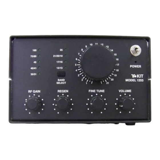
Page 51: Receiver Controls And Connections
(see sample logging sheet in this manual). As you become used to this classic method of receiver tuning, it becomes second nature, and you'll find your favorite stations or bands easily. 1253 - 49... - Page 52 DC power sources. Some DC wall adapters may work well, depending on their design Keep in mind that some wall transformers only provide AC output voltage - you MUST use a unit with 12 to 15 volts DC output. 1253 - 50...
-
Page 53: Understanding The Regeneration Control
SSB voice signal. After you've had some practice with using the regeneration control, it will become second nature, giving you a sense of real control over the performance of your receiver. 1253 - 51... -
Page 54: About The 9 Bands Of The Receiver
About the 9 Tuning Bands of your 1253 Receiver . . . The following tuning ranges are typical but can vary +5% due to manufacturing tolerances of the inductors and capacitors in the bandswitching circuits. Notice that the bands begin to overlap each other above 8 MHz. - Page 55 The higher frequencies (6 to 9) generally are most active during daylight hours. Make your own copies of the sample Shortwave Listening Log to keep track of your radio listening experiences. 1253 - 53...
-
Page 56: About The Receiver Logging Scale
We chose the "Logging Scale" approach to the calibration of the 1253 receiver because it is a proven method of accurate frequency-finding each time you use the receiver. - Page 57 Model 1253 Band/Main Tuning Calibration Chart DIAL 1 10.0 11.0 12.0 13.0 14.0 15.0 16.0 17.0 18.0 19.0 20.0 1253 - 55...
-
Page 58: Setting Up A Shortwave Listening Antenna
Nor take a direct lightning hit to damage this receiver or other equipment. If the receiver remains connected to an antenna during a storm, lightning strikes a mile away can burn out parts, particularly transistor Q1 in the 1253 receiver. 1253 - 56... -
Page 59: Tuning Ssb Voice Signals
SSB transmissions also are used by embassies, international airlines agencies of various governments, so you might find interesting voice signals on other than ham frequencies. Check with an experienced Shortwave Listener (SWL) or listings in popular Communications Magazine (available at newsstands) for more details. 1253 - 57... -
Page 60: Troubleshooting Guide
3.3 μH (orange-orange-GOLD-gold). 8. Extreme squealing or buzzing at higher settings of volume control. This "feedback" indicates an error in kit assembly. Recheck all assembly steps. (Slight feedback may begin to occur with extremely weak batteries.) 1253 - 58... -
Page 61: Experimenting With Modifications
As the years go by, we have a hunch that you'll always remember the first thrills of building and listening to your T-KIT 1253. And, because it's compact and far more sophisticated than the first receivers of yesteryear, we... - Page 62 (ARRL, Newington, CT 06111, also sold by Radio Shack™) Or, if you just want to try a single copy of one magazine that's all about ALL the signals you may hear on your T-KIT 1253, you can find the latest issue of Popular Communications at many magazine stands.
-
Page 63: Appendix: Notes For Instructors, Etc
Club Leaders, Teachers, Engineers, etc. A regeneratve circuit for a 1990's SWL receiver? This is a fair concern which we ourselves have debated, but the T-KIT 1253 is not like any regeneratve receiver you've ever bought or used before! We wanted these features: ✔... - Page 64 Simple regeneratve detectors have very low-level audio output suitable only for high- impedance earphones. Boostng such audio must be done with care – the job of the Q4 preamp circuit. This 1253 design bufers the highly sensitve oscillator/detector secton and uses the generous audio output capabilites of U1, the same TDA2611A audio IC used in TEN-TEC transceivers.
- Page 66 T-KIT Electronic Parts Identification Guide T-KIT Electronic Parts Identification Guide with Schematic Symbols with Schematic Symbols If your kit also includes parts not illustrated below, If your kit also includes parts not illustrated below, consult this manual for detailed description or illustration consult this manual for detailed description or illustration...
- Page 67 This limited warranty applies solely to KITS sold by TEN-TEC, Inc. under the trade name :T-KIT”. The terms of this warranty do not apply to other products of any kind manufactured by TEN-TEC Inc., nor shall any other warranties published by TEN-TEC Inc., or any TEN-TEC customer service policies for its manufactured products, be construed as applicable to T-KIT products.