Table of Contents
Advertisement
Advertisement
Table of Contents

Related Manuals for Century Hawk Pro


Summary of Contents for Century Hawk Pro
-
Page 1: Instruction Manual
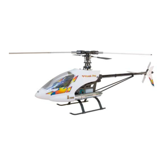
Hawk Pro Instruction Manual SPECIFICATIONS Main Rotor Diameter 49.5 in. Tail Rotor Diameter 9.3 in. Overall Length 46 in. Height 16.2 in. Engine 32 ~ 40 Ball Bearings Century Helicopter Products Designed and Developed in USA... -
Page 2: Table Of Contents
Congratulations on your purchase of Century Helicopter Product’s latest version of our HAWK series RC helicopter model. The Hawk Pro helicopter is not only ideal for beginners new to the hobby, but also for the intermediate and right on through to the expert and 3D flyers. -
Page 3: Required Items And Tools For Assembly
Required items for operation This is the general list of items required to get started on any nitro R/C helicopter. Century produces a full spectrum of accessories and tools to assemble your helicopter. The Hawk Pro is a mechanical cyclic collective pitch mixing type helicopter requiring a standard helicopter radio (the helicopter radio does not require eCCPM type mixing for this model). -
Page 4: Package Contents
Package contents: Opening The Hawk Pro for the first time Time to inventory your Hawk Pro! The helicopter is assorted into multiple bags contained inside the box. Each bag will have some parts that are not associated with that specific part bag. We recommend organizing all hardware and pieces and inventory them then keep them with their re- spective bags. -
Page 5: Section 1 Preparing The Engine
Section 1: Preparing the engine Remove the thrust washer that comes on the engine from the factory. Only use the 9x14 washer that comes with the fan and clutch package. Mount that washer first and the clutch (1.1-1.2) to the engine using thread lock. Mount the fan so the two protrud- ing portions on the underside slide into the slots machined in the clutch (1.3). -
Page 6: Section 3 Assembling The Servo Tray
Section 3: Installing servos to servo tray Insert and attach the lower throttle servo on the left side (3.1) with the output “horn” fac- ing the front of the servo tray. Install the upper collective servo above the throttle servo with the output facing the back (3.2). -
Page 7: Section 5 Muffler & Fuel Tubing
flight). Connect the fuel tank air tube (long (Optional Toki muffler for Toki .40 engine shown. Toki muffler is curved) to the muffler pressure nipple (5.3). supplied with a Hawk Pro “Toki engine and muffler combo”) Using thread lock:... -
Page 8: Section 7 Landing Gear
Section 7: Landing gear All components for installing landing gear are included with the landing gear bag. Attach the plastic U shaped struts to the bottom of the main frame and insert the metal skids when aligned (7.1). Bolt the landing gear to the main frame using provided hardware (7.2). -
Page 9: Section 9 Tail Boom Support Struts And Tail Fin Set
Section 9: Tail boom supports & tail fin set Attach the tail boom support struts to the base of the side frames using the plastic spacer on the outside of the frame (9.1) . Attach the horizontal fin (hardware found inside fin bag) and tail boom supports onto the horizontal boom clamp (9.2 use the white plastic piece found with the canopy grommets between the fin clamp and the fin). -
Page 10: Section 12 Cyclic Servo Linkage
Section 12: Cyclic servo linkage Aileron servo Before any pushrod adjustments are made center both sticks and servos on the transmitter. *Pushrod measurements include ball links from plastic end to plastic end. Adjust the two aileron control rods to 158mm and attach the two balls on the aileron servo wheel and to the two aileron bellcranks. -
Page 11: Section 16 Antenna Routing
Section 16: Antenna routing Thread the small clear tube into the guides (located on the right bottom side of the struts) on the side opposite the muffler. Insert the receiver antenna into the tube and secure to the rear area of the tail boom or one of the boom support struts. -
Page 12: Main Sub Assemblies (Exploded Views)
Main Sub-Assemblies This section will overview parts that came pre assembled from the factory. Items not attached to main sub assemblies can be found in the parts list. Main Rotor Head Main head Bell mixer block Flat washer Flat washer arm set #HI3160B Ball bearing... - Page 13 Short ball Bell Bell mixer arm Upper Side Frame Exterior #CNLR1011 mixer arm #HI3189A M3x16 Socket spacer Washout arm set cap screw (2) washer #HI3152C (comes assembled uses #CNBB0730 Ball bearing) M3x7 ball M3x7 ball bearing (2) bearing (2) Long ball #CNBB0730 #CNBB0730 #CNLR1012...
- Page 14 Collective pitch lever Swashplate set #HI3146B M3x5 flat Elevator lever washer set #HI3032B M3x5 flat washer Aileron bell- crank set M3x30 socket #HI3031B head cap screw (2) M3x7 ball bearing (4) #CNBB0730 (2 per bellcrank) Aileron bellcrank set #HI3031B Collective M6x10 ball lever set bearing (2)
- Page 15 Flybar Flybar con- M3x4 paddle set M4x5 trol arm set Flybar assembly M3x7 ball #HI3179 #HI3176 screw bearing (2) screw CNBB0730 Flybar #HW3173 Main gear Starter shaft Hex start adapter #CN0402 Autorotation M3x4 set screw using bearing set thread lock #HW3050 (inside main gear) Hardened start...
- Page 16 Lower Side Frames Servo Side Frame Set Servo side frame Lower side set #HW3115A frame set #HW3112C Front canopy mount set #HI3129 Fuel tank set Engine mount #HI3138A #HW3017 Tail Section Interior Torque tube collar (also includes male end from page 17) #HI3065 Tail gear box (left &...
- Page 17 Tail pitch lever Tail pitch plate Tail pitch plate assembly Tail pitch plate #HI3087A Tail pitch plate assembly assembly #HI3087A (brass slider) #HI3087A M2 short ball on tail pitch plate connects here M3x16 socket M3x16 head screw socket connects here head screw Ball bearing...
-
Page 18: Replacement Part List And Photos
LOWER SIDE FRAMES CNLR1013 M2 Ball joint with short standoff HW3115A SERVO MOUNT FRAME SET CN3033A Black Torpedo Muffler 32-40 Hawk Pro Upgrade Parts & Accessories CN2208B Metal Swashplate Anti-rotation Bracket - black CN0427 Hex start wand with one-way bearing CN2208P... - Page 19 Hawk Pro Replacement Parts HW3000 CN0402 CN2226 HI3007 HI3009 Cooling fan Starter bearing blocks Hex start adapter Hardened start shaft Hardware pack HI3010 HW3011 HW3017 HI3020A HW3024 Clutch bell Clutch shoe Collective pitch lever set Engine mount (.30 size) Cooling fan shroud...
- Page 20 HI3099 HI3102A HI3106A HI3107 HI3112C Upper side frame set Lower side frame set Tail pitch lever Tail pushrod guides Tail rotor blades HW3115A HI3122 HW3123 HW3127A HI3129 Canopy frame mounts Landing struts Landing skids Canopy front mounts Servo frame set HI3130B HI3131M HI3133A...
-
Page 21: Upgrades
These caps and washers will add a lot Kit comes with a hollow fiber tube and to the looks of our Hawk Pro (colors: Completely eliminate slop from flexing CNC base mounts that allow you to Heavy duty dual B.B and a trust... - Page 22 HI3181A 85 degree hardness ing, recording or otherwise, without the prior CN265501 carbon angle tip 550mm damping rubbers written permission of the publisher, Century CN260853 carbon tail blades 85mm CN265522 carbon flat tip 550mm Helicopter Products.