Table of Contents
Advertisement
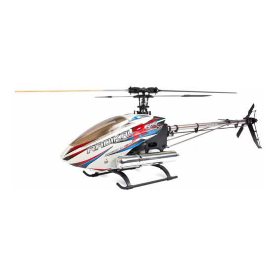
Kit Features:
Lightweight yet extremely strong G10 or carbon fiber frames.
High gloss large diameter 25mm tail boom with belt drive system.
Blade grips accommodate blades 12mm (LT) to 18mm (HD) blade roots.
300 mL fuel tank for long engine run time.
Convenient and easy access to spark plug.
Triple bearing supported blade grips and tail blade grips.
Machined center dual ball bearing swashplate for 120 degree CCPM.
Adjustable bell-hiller ratio allows tuning for preferred cyclic response (HD)
Tunable flight characteristics for stability or speed.
© 2010 Century Helicopter Products - All rights reserved.
Specifications:
Length: 1366mm
Height: 381mm
Width: 260mm
Main rotor diameter: 1435mm
Tail rotor diameter: 262mm
Main rotor blades: 600mm-640mm
Tail rotor blades: 95mm
Version 1.10
Advertisement
Table of Contents

Related Manuals for Century Radikal G20


Summary of Contents for Century Radikal G20
-
Page 1: Specifications
Machined center dual ball bearing swashplate for 120 degree CCPM. Tail rotor blades: 95mm Adjustable bell-hiller ratio allows tuning for preferred cyclic response (HD) Tunable flight characteristics for stability or speed. Version 1.10 © 2010 Century Helicopter Products - All rights reserved. -
Page 2: Thank You
Thank You Congratulations on the purchase of the latest Century Gasser series, the Radikal G20. You’re about to build one of the world’s first fully functional 3D aerobatic helicopters powered by the Zenoah 20cc gasoline engine. Be sure to read through and follow the instructions during the build. -
Page 3: Required Items
(c) Purchaser Remedy- Century Helicopter Products’s sole obligation hereunder shall be that Century Helicopter Products will, at its option, (i) repair or (ii) replace, any Product determined by Century Helicopter Products to be defective. In the event of a defect, these are the Purchaser’s exclusive remedies. -
Page 4: Radio Control
Radikal Gasser AMA RULES & REGULATIONS General 1) I will not fly my model aircraft in sanctioned events, air shows or model flying demonstrations until it has been proven to be airwor- thy by having been previously, successfully flight tested. 2) I will not fly my model higher than approximately 400 feet within 3 miles of an airport without notifying the airport operator. - Page 5 HEAD ASSEMBLY (HD VERSION) Radikal Gasser BAG 1 Do not open all the bags prior to starting assembly. Open the bags step by step as you go through the instruction manual. The components are bagged to make assembly easier. The next few pages will pertain to the assembly of the head. Please follow the instructions based on the head type you own.
- Page 6 HEAD ASSEMBLY (LT VERSION) Radikal Gasser BAG 1 Do not open all the bags prior to starting assembly. Open the bags step by step as you go through the instruction manual. The components are bagged to make assembly easier. The next few pages will pertain to the assembly of the head. Please follow the instructions based on the head type you own.
- Page 7 HEAD ASSEMBLY (HD VERSION) Radikal Gasser BAG 1 Pushrod assembly (parts 2 through 4) is already assembled but check that the length is actually 43mm (center to center). As the pushrods are built and installed they should be checked for tightness. Press one ball link onto each double studded steel ball, making sure that pressure is applied from the side of the ball link with circle mark.
- Page 8 HEAD ASSEMBLY (LT VERSION) Radikal Gasser BAG 1 Pushrod assembly (parts 2 through 4) is already assembled but check that the length is actually 43mm (center to center). As the pushrods are built and installed they should be checked for tightness. Press one ball link onto each double studded steel ball, making sure that pressure is applied from the side of the ball link with circle mark.
- Page 9 HEAD ASSEMBLY (HD VERSION) Radikal Gasser There are two types of dampeners provided. The hard black plastic dampeners BAG 1 (HI6520A) should only be used for hard 3D flying. Press in the head dampers into the rotor head block. Lubricate the inside surface of each damper with light oil.
- Page 10 HEAD ASSEMBLY (LT VERSION) Radikal Gasser BAG 1 Press in the head dampers into the rotor head block. Lubricate the inside surface of each damper with light oil. Press one M9X13 flat washer into the end of each blade grip. If necessary use a socket that matches the diameter of the washer and press into position.
- Page 11 HEAD ASSEMBLY (HD VERSION) Radikal Gasser BAG 1 Slide the washout guide and the rotor head onto the main shaft. Insert the M4x22 shoulder socket cap screw through the rotor head hub and main shaft and secure with one M4 locknut, torque down the screw.
- Page 12 HEAD ASSEMBLY (LT VERSION) Radikal Gasser BAG 1 Slide the washout guide and the rotor head onto the main shaft. Insert the M3X18 shoulder socket cap screw through the rotor head hub and main shaft and secure with one M3 locknut, torque down the screw. Apply Medium threadlock to the M2.5x8 sock- et cap screws and tighten into the bot- tom of the rotor head block to clamp...
- Page 13 WASHOUT AND SWASHPLATE Radikal Gasser BAG 1 M3 L=7.8MM CNLR1014 M3X5X3 HW6205 CNBB0730 M10x12x5 HI3152C M3x5x0.5 CNLR1003 CNM3x16BHCS M3 L=18MM Ø2x12 Comes pre-assembled It is up to you to determine whether this assembly is correct. Please make sure to check it prior to installation. Description Part # Washout Set (10mm) (...
- Page 14 WASHOUT AND SWASHPLATE (LT VERSION) Radikal Gasser BAG 1 Comes pre-assembled It is up to you to determine whether this assembly is correct. Please make sure to check it prior to installation. Starting with the inside race, apply Medium threadlock to the silver steel balls and attach them across from each other.
- Page 15 HEAD PUSHROD LENGTHS (HD VERSION) Radikal Gasser BAG 1 25.5 HELPFUL TOOL: PART# CN2219A: BALL LINK EASY DRIVER DRAWN TO A SCALE OF 1-TO-1. YOU CAN MATCH NOTICE SIZE OF HOLES ON BALL LINKS YOUR LINKS UP TO THIS PAGE FOR PROPER MEA- SUREMENTS.
- Page 16 HEAD PUSHROD LENGTHS (LT VERSION) Radikal Gasser BAG 1 NOTICE SIZE OF HOLES ON BALL LINKS THE SIDE WITH THE SMALLER HOLE SHOULD FACE OUTWARDS DRAWN TO A SCALE OF HELPFUL TOOL: 1-TO-1. YOU CAN MATCH YOUR LINKS UP TO THIS PAGE FOR PROPER MEA- SUREMENTS.
- Page 17 SKELETAL SUPPORT BRACES Radikal Gasser This bearing is already pressed BAG 2 into the bearing block. COMES PRE-ASSEMBLED Description Part # HW6117G20 Landing Gear Frame( 引擎座底板) CNM3x10FHCS Flush Head Cap Screws( 斜头内六角螺丝)M3x10 HW6119 Box Frame Support( 机身加强支架) HW6042G Lower Main Shaft Bearing Block(主轴下轴承座) CNM3x12BHCS Button Head Cap Screw( 圆头内六角螺丝)M3x12 CNBB1022...
- Page 18 REAR SIDEFRAME (LEFT) Radikal Gasser BAG 2 Flanged bearing already pressed into frames. Make sure the flange is facing inwards. This bearing is already pressed into the bearing block. Dry fit the electronics tray built from the previous page into the left rear sideframe prior to mounting onto the skeletal support frame assembly.
-
Page 19: Fuel Tank
FUEL TANK Radikal Gasser BAG 2 Pay close attention when assembling the fuel tank. The vent tube must be bent and facing upwards when installed into the rubber stopper. There are 3 holes on the rubber stopper but notice only 2 are through holes. - Page 20 REAR SIDEFRAME (RIGHT) Radikal Gasser BAG 2 When installing the elevator bellcrank, make sure to apply medium CA to the M3x12 button head cap screw. Assemble the aileron bellcranks by first pressing in the 3x7x3 bearing followed by the 3x5x7.5 spacer. In- stall the remaining bearing along with the metal balls.
- Page 21 CLUTCHBELL ASSEMBLY Radikal Gasser BAG 2 CNBB1015 CNM4x4SS CNBB513 CNBB1524 CNBB511 The Radikal uses the regular starting shaft and hex coupler as to align the clutch to the clutchbell. Clean both the starting shaft and the inside race of the bearing inside the clutchbell and the inside race of the top starting shaft bearing.
- Page 22 ZENOAH 20CC ENGINE PREPARATION Radikal Gasser It is not so apparent how the propeller hub is attached to the engine. First undo the nut and remove the propeller washer. Screw down A 13mm lock nut is supplied in the kit to aid in the removal of the the original nut onto the stud followed by the locknut.
- Page 23 CLUTCHSHOE AND FAN ASSEMBLY Radikal Gasser BAG 3 Bearing is pre-installed Install the clutch temporarily and do a dry fitment into your clutch bell that is mounted to your frames. If your clutch shoe is sitting outside the clutch bell when your engine is mounted to your frames, you will most likely need 2 clutch shims.
- Page 24 EFI PICK UP Radikal Gasser BAG 2 Mount the plate onto the engine first and tighten the M4x10 Flush Head Cap Screws. After you have installed the plate, then install the sensor. The sensor can be adjusted slightly to advance or retard timing. Description Part # CNM4x10FHCS...
- Page 25 ELECTRONICS TRAYS Radikal Gasser BAG 3 Start by installing the four M2.5x6 flush head cap screws into the lower electronics tray by using medium threadlock. Use the M3x30 Phillips tapping screws to mount the canopy hook. Do not overtighten this as you can strip the plastic. Next apply medium threadlock to the remaining four M2.5x6 flush head cap screws and install them into the upper elec- tronics tray.
- Page 26 FRONT SIDE FRAMES Radikal Gasser BAG 3 Make sure when fitting the electronics trays that you have a com- plete mating with the upper side frames. If the keys do not fit into the slots on the upper side frames and you tighten down on the screws, your frame will be crooked.
- Page 27 MOUNTING MOTOR Radikal Gasser BAG 2 Loosely fit the CNM4X10 cap screws that hold the engine on the plate. Then line up the bearing assembly in the upper portion of the frames. Keep this loose for now until you are ready to mesh the pinion gear with the main gear.
- Page 28 ATTACHING FRONT FRAME ASSEMBLY Radikal Gasser BAG 2 CNM3x8BHCS When mounting the front frames to the rear frames, make sure the keyed split matches up properly prior to tightening the eight M3x8 button head cap screws. This is very important as you can warp the frames if it’s not set in place when tightening down.
-
Page 29: Landing Gear
LANDING GEAR Radikal Gasser LANDING GEAR PACKAGE Install the landing skids onto the landing struts one side at a time. After installing the landing skids, position, the landing struts on the skids so that they match up with the mounting positions on the frames. -
Page 30: Main Gear Assembly
MAIN GEAR ASSEMBLY Radikal Gasser BAG 3 Apply medium threadlock to the four M3x6 flush head cap screws and install through the tail drive gear tightening onto the driven tail hub. Apply medium threadlock to the six M3x8 flush head cap screws and install onto the main gear with the auto-rotation one way bearing. - Page 31 ATTACHING HEAD AND MAIN GEAR Radikal Gasser BAG 3 CNM4x4SS Apply grease to the thrust bearing. Place the Main Gear assembly into the frames. Insert the main shaft with head assembly through the bear- CNM2.5x8CS ing blocks while lining up the thrust bearing, and mast stopper while go- ing through the Main Gear assembly.
- Page 32 TAIL BOOM COMPONENTS Radikal Gasser BAG 4 When installing all the hardware onto the boom, make sure you do so prior to installing the tail gearbox. Oth- erwise you will not be able to once your tail gearbox is mounted. Do not apply the zip ties until the very end when you are sure of the positions of the tail control rod guides.
- Page 33 TAIL GEARBOX Radikal Gasser BAG 4 The taller lip should When pressing the bearing retainers into the tail gear box face outwards. plate, make sure you are pressing it into the correct side. The left and right side are different. If you do not do this, it will be difficult to remove this pieces once it’s pressed in.
-
Page 34: Tail Rotor Assembly
TAIL ROTOR ASSEMBLY Radikal Gasser BAG 4 Comes pre-assembled. Slide one M3x18 special socket cap screw from the inside of the tail rotor grip and position the first M3x10x1.5 spacer, insert the tail blade, another spacer and secure using one M3 locknut from the molded recess on the outside. - Page 35 TRANSMISSION CASE Radikal Gasser BAG 4 You may notice the boom and the tail transmission case is scuffed. When orienting the belt the front trans- This is done during the manu- mission pulley as viewed from the top facturing process to ensure a should be turning counter-clockwise.
- Page 36 ATTACHING TAIL TO MAIN FRAME Radikal Gasser BAG 4 Install the tail assembly onto the main frames by using threadlock on eight the M3x8 button head cap screws. Make sure to install two screws oppo- site of each other on either side and tighten down making sure the transmis- sion gear is properly meshed with the tail drive gear.
- Page 37 INSTALLING SERVOS Radikal Gasser BOLTS BAG To secure the servo mounting tabs, the best thing to use is a set of hemostats or needle nose pliers to hold the tab in place while tightening the servo mount- ing screws. Be sure to use a large enough Phillips screw drive so as to not strip the head of the Phillips tapping screws.
- Page 38 ADJUSTING PUSHROD LENGTHS Radikal Gasser BOLTS BAG HELPFUL TOOL: PART# CN2219A: BALL LINK EASY DRIVER 72.2 HEL PFUL TOOL 93.6 76.4 PART# CN2255: CONTROL ROD SETUP GAUGE NOTICE SIZE OF HOLES ON BALL LINKS Description Part # HI6145 Ball Link(塑胶球头连接头) HW6192D Pushrod(连杆)L=85MM HW6192D...
- Page 39 ATTACHING MUFFLER Radikal Gasser Shown is the optional Torpedo Slim Tuned Gas- ser Muffler. This is not included in your kit. When installing the bolts to hold the muffler, au- tomotive Goop® can be used as a threadlocking adhesive. This will keep the bolts in place. Anoth- er suggestion is to bring the engine to operating temperatures and then re-torque the M5 bolts holding the muffler in place.
- Page 40 INSTALLING ELECTRONICS Radikal Gasser INCLUDED INCLUDED INCLUDED The electronics configuration is shown as an example of how to mount the electronics. It is not necessary to mount your electronics this way. Part # Description NOT INCLUDED Receiver(接收机) NOT INCLUDED Receiver Battery( 电池) Gyro Isolation Foam( 防震垫片) NOT INCLUDED NOT INCLUDED...
- Page 41 CANOPY Radikal Gasser It will be necessary to cut the windshield out from the mold. It is recommended to use curved hobby scissors for this pro- cess. If the lines are not smooth, you can use 200 grit sand- paper to sand the edges. Prior to making the holes for the canopy chin mount, you should mount your canopy to the When drilling the holes into...
- Page 42 If you have the HD head, the main blade screw and bolt are going to be M5 parts. Congratulations on finishing the build of the Radikal G20 helicopter. Please follow your instruction manual on setting up your transmit- ter and gyro systems. Also it is very important that you follow the instructions included with the Zenoah G20 engine for the break in process and finally tuning the engine.
- Page 43 PERSONAL BUILD NOTES Radikal Gasser Page 43...