Advertisement
Quick Links
Download this manual
See also:
Owner's Manual
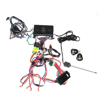
M M o o d d e e l l 5 5 7 7 1 1 X X P P
I I n n s s t t a a l l l l a a t t i i o o n n G G u u i i d d e e
P P y y t t h h o o n n
NOTE:
This product is intended for installation by a professional installer only!
Any attempt to install this product by any person other than a trained professional
may result in severe damage to a vehicle's electrical system and components.
© 2005 Directed Electronics—Vista, CA
N572P 07-05
Advertisement

Related Manuals for Python 571XP


Summary of Contents for Python 571XP
- Page 1 M M o o d d e e l l 5 5 7 7 1 1 X X P P I I n n s s t t a a l l l l a a t t i i o o n n G G u u i i d d e e P P y y t t h h o o n n NOTE: This product is intended for installation by a professional installer only!
- Page 2 t t a a b b l l e e o o f f c c o o n n t t e e n n t t s s w w a a r r n n i i n n g g ! ! s s a a f f e e t t y y f f i i r r s s t t ......... . 3 3 testing the neutral safety switch .
- Page 3 w w a a r r n n i i n n g g ! ! s s a a f f e e t t y y f f i i r r s s t t The following safety warnings must be observed at all times: ■...
- Page 4 i i n n s s t t a a l l l l a a t t i i o o n n p p o o i i n n t t s s t t o o r r e e m m e e m m b b e e r r b b e e f f o o r r e e b b e e g g i i n n n n i i n n g g t t h h e e i i n n s s t t a a l l l l a a t t i i o o n n I I M M P P O O R R T T A A N N T T ! ! This product is designed for fuel-injected, automatic transmission vehicles only.
- Page 5 m m o o u u n n t t i i n n g g t t h h e e a a n n t t e e n n n n a a The antenna position should be discussed with the vehicle’s owner prior to installation, since the antenna may be visible to the vehicle’s operator.
- Page 6 s s t t a a t t u u s s L L E E D D Things to remember when positioning the status LED: ■ It should be visible from both sides and the rear of the vehicle, if possible. ■...
- Page 7 o o b b t t a a i i n n i i n n g g c c o o n n s s t t a a n n t t 1 1 2 2 V V We recommend two possible sources for 12V constant: The (+) terminal of the battery, or the constant 12V supply to the ignition switch.
- Page 8 H H o o w w t t o o f f i i n n d d t t h h e e s s t t a a r r t t e e r r w w i i r r e e w w i i t t h h y y o o u u r r m m u u l l t t i i m m e e t t e e r r : : 1.
- Page 9 I I M M P P O O R R T T A A N N T T ! ! Do not test tachometer wires with a test light or logic probe. The vehicle will be damaged. H H o o w w t t o o f f i i n n d d a a t t a a c c h h o o m m e e t t e e r r w w i i r r e e w w i i t t h h y y o o u u r r m m u u l l t t i i m m e e t t e e r r : : 1.
- Page 10 ______ H H 1 1 / / 1 1 O O R R A A N N G G E E ( ( - - ) ) 5 5 0 0 0 0 m m A A A A R R M M E E D D O O U U T T P P U U T T ______ H H 1 1 / / 2 2 W W H H I I T T E E...
- Page 11 h h e e a a v v y y g g a a u u g g e e r r e e l l a a y y s s a a t t e e l l l l i i t t e e w w i i r r i i n n g g d d i i a a g g r r a a m m ______ P P U U R R P P L L E E ( ( + + ) ) S S T T A A R R T T E E R R O O U U T T P P U U T T T T O O S S T T A A R R T T E E R R ( ( S S T T A A R R T T E E R R S S I I D D E E ) )
- Page 12 d d o o o o r r l l o o c c k k h h a a r r n n e e s s s s ( ( H H 4 4 ) ) w w i i r r i i n n g g d d i i a a g g r r a a m m ______ H H 4 4 / / 1 1 G G R R E E E E N N...
- Page 13 ( ( + + ) ) P P o o s s i i t t i i v v e e L L i i g g h h t t F F l l a a s s h h O O u u t t p p u u t t ( ( - - ) ) L L i i g g h h t t F F l l a a s s h h O O u u t t p p u u t t N N O O T T E E : : For parking light circuits that draw 10 amps or more, the internal jumper must be switched to a (-) light flash output.
- Page 14 H H 1 1 / / 4 4 B B L L A A C C K K / / W W H H I I T T E E ( ( - - ) ) 2 2 0 0 0 0 m m A A d d o o m m e e l l i i g g h h t t s s u u p p e e r r v v i i s s i i o o n n o o u u t t p p u u t t Connect this wire to the optional domelight supervision relay as shown below: I I M M P P O O R R T T A A N N T T ! ! This output is only intended to drive a relay.
- Page 15 H H 1 1 / / 1 1 0 0 B B R R O O W W N N ( ( - - ) ) h h o o r r n n h h o o n n k k o o u u t t p p u u t t This wire supplies a (-) 200 mA output that can be used to honk the vehicle horn.
- Page 16 r r e e l l a a y y s s a a t t e e l l l l i i t t e e i i n n t t e e r r f f a a c c e e w w i i r r e e c c o o n n n n e e c c t t i i o o n n g g u u i i d d e e All except the red heavy gauge wires leading from the relay satellite are used to energize high current circuits in the vehicle.
- Page 17 P P I I N N K K / / W W H H I I T T E E ( ( + + ) ) o o u u t t p p u u t t t t o o s s e e c c o o n n d d i i g g n n i i t t i i o o n n / / a a c c c c e e s s s s o o r r y y c c i i r r c c u u i i t t Connect this wire to the second ignition or accessory wire in the vehicle (selectable menu feature 2-9).
- Page 18 N N O O T T E E ! ! A 1-amp diode must be installed in line on the factory wire between the wait-to-start indicator and the ECM. (See the following diagram for details.) H H 2 2 / / 3 3 G G R R E E E E N N / / W W H H I I T T E E f f a a c c t t o o r r y y r r e e a a r r m m o o u u t t p p u u t t This wire sends a negative pulse every time the remote start shuts down or the doors are locked.
- Page 19 r r e e m m o o t t e e s s t t a a r r t t h h a a r r n n e e s s s s ( ( H H 3 3 ) ) w w i i r r e e c c o o n n n n e e c c t t i i o o n n g g u u i i d d e e H H 3 3 / / 1 1 B B L L U U E E / / W W H H I I T T E E s s t t a a t t u u s s / / d d e e f f o o g g g g e e r r o o u u t t p p u u t t This wire supplies a 200mA output as soon as the module begins the remote start process.
- Page 20 F F i i g g u u r r e e A A F F i i g g u u r r e e B B I I M M P P O O R R T T A A N N T T ! ! Always perform the Vehicle Safety Check section of this guide to verify that the vehicle cannot be started in ANY drive gear and that the override switch is functioning properly.
- Page 21 t t e e s s t t i i n n g g t t h h e e n n e e u u t t r r a a l l s s a a f f e e t t y y s s w w i i t t c c h h 1.
- Page 22 D D i i a a g g r r a a m m A A - - G G e e n n e e r r a a l l M M o o t t o o r r s s t t r r u u c c k k s s , , s s p p o o r r t t u u t t i i l l i i t t y y v v e e h h i i c c l l e e s s a a n n d d c c o o l l u u m m n n s s h h i i f f t t i i n n g g p p a a s s s s e e n n g g e e r r v v e e h h i i c c l l e e s s : : D D i i a a g g r r a a m m B B - - P P r r e e - - 1 1 9 9 9 9 6 6 D D o o d d g g e e D D a a k k o o t t a a p p i i c c k k u u p p s s w w i i t t h h 2 2 .
- Page 23 1 1 9 9 9 9 5 5 a a n n d d n n e e w w e e r r v v e e h h i i c c l l e e a a n n t t i i - - t t h h e e f f t t s s y y s s t t e e m m s s ( ( i i m m m m o o b b i i l l i i z z e e r r s s ) ) 1995 and newer vehicle anti-theft systems (immobilizers) require a bypass module.
- Page 24 transceiver will excite the transponder, which is located (but not visible) in the head of the ignition key. The key transponder will then send a unique code back to the transceiver for evaluation. If the code matches a valid code of the system, the vehicle will be allowed to start. Most of these transponder-based systems can be bypassed using p p / / n n 5 5 5 5 5 5 U U or 5 5 5 5 6 6 U U .
- Page 25 p p l l u u g g - - i i n n L L E E D D a a n n d d v v a a l l e e t t / / p p r r o o g g r r a a m m s s w w i i t t c c h h These plug into the module.
- Page 26 p p r r o o g g r r a a m m m m i i n n g g j j u u m m p p e e r r s s l l i i g g h h t t f f l l a a s s h h ( ( + + ) ) / / ( ( - - ) ) This jumper is used to determine the light flash output polarity.
- Page 27 t t r r a a n n s s m m i i t t t t e e r r / / r r e e c c e e i i v v e e r r l l e e a a r r n n r r o o u u t t i i n n e e The system comes with one transmitter that has been taught to the receiver.
- Page 28 T T r r a a n n s s m m i i t t . . While H H O O L L D D I I N N G G the Valet/Program switch, press the button on the transmitter that you would like to control the selected receiver channel.
- Page 29 t t r r a a n n s s m m i i t t t t e e r r c c o o n n f f i i g g u u r r a a t t i i o o n n s s The transmitters can be programmed with the separate or single button arm/disarm configurations by using the Auto-learn functions in the Transmitter/Receiver Learn Routine.
- Page 30 s s y y s s t t e e m m f f e e a a t t u u r r e e s s l l e e a a r r n n r r o o u u t t i i n n e e The System Features Learn Routine™...
- Page 31 One, if you just programmed Feature 1-2 and you next want to program Feature 1-3 to off, release the Valet/Program switch. Press and release it once to advance from Feature 1-2 to Feature 1-3. Then press it once more and H H O O L L D D it. The LED will flash in groups of 3 and the horn will honk 3 times (if connected) to confirm that you have accessed Feature 1-3.
- Page 32 f f e e a a t t u u r r e e m m e e n n u u s s Factory default settings are indicated in b b o o l l d d in the following feature tables. m m e e n n u u # # 1 1 F F E E A A T T U U R R E E D D E E F F A A U U L L T T - - L L E E D D O O N N S S E E T T T T I I N N G G...
- Page 33 m m e e n n u u # # 2 2 F F E E A A T T U U R R E E D D E E F F A A U U L L T T - - L L E E D D O O N N S S E E T T T T I I N N G G L L E E D D O O F F F F S S E E T T T T I I N N G G N N U U M M B B E E R R ( ( P P R R E E S S S S C C H H A A N N N N E E L L 1 1 ) )
- Page 34 1 1 - - 2 2 C C H H I I R R P P S S O O N N / / O O F F F F : : This feature controls the chirps that confirm arming and disarming of the system. A siren or horn must be connected to the H1/10 BROWN wire.
- Page 35 1 1 - - 1 1 1 1 C C H H A A N N N N E E L L 2 2 L L I I N N K K I I N N G G ( ( N N O O N N E E ) ) / / ARM, DISARM, BOTH: : When programming to validity or timed output this can be programmed to activate when arming or disarming (or both) with the transmitter.
- Page 36 2 2 - - 2 2 T T A A C C H H W W I I R R E E S S E E N N S S E E / / V V O O L L T T A A G G E E S S E E N N S S E E : : If the tachometer signal wire is used, this feature must be left in the default (tach wire connected) setting.
- Page 37 2 2 - - 1 1 2 2 A A N N T T I I - - G G R R I I N N D D O O N N / / O O F F F F : : With the anti-grind On (default) the ground-when-armed output will be active during remote start operation.
- Page 38 s s h h u u t t d d o o w w n n d d i i a a g g n n o o s s t t i i c c s s The unit has the ability to report the cause of the last shutdown of the remote start system. T T o o e e n n t t e e r r d d i i a a g g n n o o s s t t i i c c m m o o d d e e : : Turn the ignition off.
- Page 39 r r a a p p i i d d r r e e s s u u m m e e l l o o g g i i c c The Rapid Resume Logic feature ensures that when the security system is powered back up after power has been disconnected, the system will resume the same state it was in before power was lost.
- Page 40 t t i i m m e e r r m m o o d d e e By pressing the remote buttons the parking lights will flash 4 times and then start the vehicle and run for the set dura- tion.
- Page 41 1. Test the BRAKE shutdown circuit: With the vehicle in Park (P), activate the remote start system. Once the engine is running, press the brake pedal. The engine should shut down immediately. If the engine continues to run, check the brake circuit connection. 2.
- Page 42 t t r r o o u u b b l l e e s s h h o o o o t t i i n n g g ■ T T h h e e i i g g n n i i t t i i o o n n c c o o m m e e s s o o n n , , b b u u t t t t h h e e s s t t a a r r t t e e r r w w i i l l l l n n o o t t c c r r a a n n k k . . Does it start with the key in the ignition? If so, does the vehicle have a VATS Pass-Key system? Will it start with the brake pedal depressed? (Make sure to disconnect the brake shutdown when performing this test.) If so, it may have a brake/starter interlock.
- Page 43 6. Check connections. The two red heavy gauge input wires on the relay satellite should have solid connections. "T-taps", or "scotch locks" are not recommended for any high current heavy gauge wiring. Also, if the vehicle has more than one 12-volt input wire, then connect one red wire to each. ■...
- Page 44 w w i i r r i i n n g g q q u u i i c c k k r r e e f f e e r r e e n n c c e e g g u u i i d d e e 4 4 4 4 ©...
- Page 45 r r e e l l a a y y s s a a t t e e l l l l i i t t e e w w i i r r i i n n g g q q u u i i c c k k r r e e f f e e r r e e n n c c e e g g u u i i d d e e 4 4 5 5 ©...