Table of Contents
Advertisement
Quick Links
Advertisement
Table of Contents

Related Manuals for Samsung SCB-2005


Summary of Contents for Samsung SCB-2005
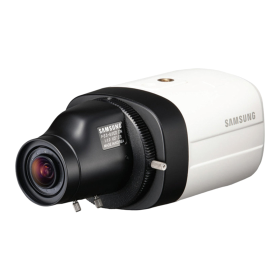
- Page 1 High Resolution Camera User Manual SCB-2005...
-
Page 2: User Manual
Samsung Techwin. Disclaimer Samsung Techwin makes the best to verify the integrity and correctness of the contents in this document, but no formal guarantee shall be provided. Use of this document and the subsequent results shall be entirely on the user’s own responsibility. - Page 3 Before operating the camera, confirm the camera model and correct input power voltage. To help you understand this manual thoroughly, we’ll introduce our model description. ■ SCB-2005 SERIES • NTSC MODEL SCB-2005N / 2005ND • PAL MODEL SCB-2005P / 2005PD •...
-
Page 4: Safety Information
Safety information CAUTION RISK OF ELECTRIC SHOCK. DO NOT OPEN TO REDUCE THE RISK OF ELECTRIC SHOCK, DO NOT REMOVE CAUTION: COVER (OR BACK) NO USER SERVICEABLE PARTS INSIDE. REFER SERVICING TO QUALIFIED SERVICE PERSONNEL. This symbol indicates that dangerous voltage consisting a risk of electric shock is present within this unit. - Page 5 If this product fails to operate normally, contact the nearest service center. never disassemble or modify this product in any way. (samsung is not liable for problems caused by unauthorized modifications or attempted repair.) When cleaning, do not spray water directly onto parts of the product.
-
Page 6: Fcc Statement
Safety information fCC sTATemeNT This device complies with part 15 of the FCC Rules. Operation is subject to the following two conditions : This device may not cause harmful interference, and This device must accept any interference received including interference that may cause undesired operation. - Page 7 Apparatus shall not be exposed to dripping or splashing and no objects fi lled with liquids, such as vases, shall be placed on the apparatus Samsung Techwin cares for the environment at all product manufacturing stages to preserve the environment, and is taking a number of steps to provide customers with more environment-friendly products.The Eco mark represents...
-
Page 8: Table Of Contents
Contents INTRODUCTION Features What’s included Component names and Functions CONNECTION Lens Connecting to Monitor Connecting to Power Using coaxial communications SETUP Menu Confi gration Menu Setup TROUBLESHOOTING Troubleshooting SPECIFICATIONS Specifi cations Dimension 8_ Contents... - Page 9 The camera is able to recognize the concerntration of fog in the image, and automatically defog, correct image of the bad weather such as fog, rain, mist, fumes, etc to make it clear. ssdR (samsung super dynamic Range) For images with high contrast between bright and dark areas from difficult lighting conditions such as backlighting, this camera selectively illuminates darker areas while retaining the same light level for brighter areas to even out the overall brightness.
- Page 10 Introduction WHAT’S INCLUDED Check if the following items are included in the product package. High Resolution Camera Quick Manual SCB-2005 C Mount Adapter Camera Quick Manual 10_ Introduction...
-
Page 11: Component Names And Functions
COMPONENT NAMES AND FUNCTIONS Front ❶ ➌ ➍ ➋ ❶ Tripod Mounting Bracket Screw Hole : Used to fix the Tripod Mounting Bracket . The screw size : use this screw to fix the mounting bracket . 1/4” -20UNC(20THREAD) L : 4.5mm±0.2mm (ISO Standard), or 0.197”... - Page 12 ➎ ➑ POWER VIDEO CLASS 2 ONLY <AC24V/DC12V (SCB-2005)> ➎ Power input terminal : Connects to the power appropriate to each model. ➏ Video OUT Terminal : Sends video signal and connects to the video input terminal of the monitor.
- Page 13 Connection Lens The lens is not supplied with this camera. Purchase a lens suitable for your environment. This camera accepts the auto iris lens and both C and CS-mount lens. To use the functions of this camera effectively it is recommended that a DC type Auto Iris lens is used.
- Page 14 Connection 2. Turn the C-Mount lens clockwise to install it. C-Mount Adapter 3. Set focus of camera using Back Focus Control Lever of camera side after combining C-Mount lens. Note that C-Mount adaptor is not supplied with camera. When Install a CS-Mount lens Remove the protective cover from the front of the camera, and turn the CS-Mount lens clockwise to install it.
-
Page 15: Connecting To Monitor
You can connect power as shown in the following figure. For AC / DC power SCB-2005 • Since SCB-2005 the power specification supports both AC and DC, connect AC 24V, 500mA Adaptor or DC 12V, 500mA Adaptor. POWER VIDEO... -
Page 16: Using Coaxial Communications
Connection SCB-2005D For DC power • Since SCB-2005D the power specification support DC, connect DC 12V, 500mA POWER VIDEO Adaptor. Power When the resistance value of copper wire is at [20°C(68°F)] Copper wire size (AWG) #24(0.22mm #22(0.33mm #20(0.52mm #18(0.83mm Resistance (Ω/m) 0.078 0.050 0.030... - Page 17 CAMERA CONTROLLER MENU/ENTER OSD KEY UP KEY JOYSTICK UP DOWN DOWN KEY JOYSTICK DOWN LEFT LEFT KEY JOYSTICK LEFT RIGHT RIGHT KEY JOYSTICK RIGHT ALARM NETWORK BACKUP ZOOM FREEZE BACKUP SEARCH TELE WIDE VIEW PRESET MODE AUDIO ALRAM MENU DVD RECORDER OPEN/CLOSE RETURN - Video Cable...
-
Page 18: Setup
Setup MENU CONFIGRATION mAIN seTUp leNs ● ● MANUAL ● ● ● BRIGHTNESS SHUTTER expOsURe ● ● SENS-UP RETURN defOG ● ● ● AUTO MANUAL ● ● OUTDOOR ● INDOOR WhITe bAl AWC → SET ● MANUAL ● bACKlIGhT ● ●... - Page 19 MAIN SETUP 1.LENS Select the function using Change the status 2.EXPOSURE the Function Setup switch. using the Function Setup switch. DEFOG WHITE BAL BACKLIGHT SSNR3 DAY/NIGHT AUTO 8.SPECIAL 9.EXIT SAVE Select a desired function using the Function Setup switch. Place the cursor over a desired item. Set up a selected item by using the Function Setup switch.
- Page 20 Setup EXPOSURE 1. When the SETUP menu screen is displayed, select EXPOSURE by using the Function Setup switch so that the arrow indicates 'EXPOSURE'. Select a desired mode using the Function EXPOSURE SETUP Setup switch. 1.BRIGHTNESS IIIIIIIII IIIIIIII BRIGHTNESS : Adjusts the video brightness. 2.SHUTTER ...
- Page 21 White Balance operation may become unstable. BACKLIGHT The SCB-2005 is designed to deliver a distinctive subject and background at the same time, even when the subject is backlight, by adopting a function of the proprietary W6 DSP chip.
- Page 22 Setup 2. Select a desired mode using the Function Setup switch depending on the camera purpose. UseR blC : Enables a user to directly BLC SETUP select a desired area from a ▶ 1.LEVEL MIDDLE picture, and to view the area 2.TOP IIIII ...
- Page 23 DAY/ NIGHT You can display pictures in color or black and white. 1. When the SETUP menu screen is displayed, select ‘DAY/NIGHT’ by using the Up and Down buttons so that the arrow indicates ‘DAY/NIGHT’. 2. Select a desired mode using the Left and Right buttons according to the picture display you want.
- Page 24 Setup IMAGE ADJ IMAGE SETUP 1) When the SPECIAL menu screen is displayed, ▶ 1.MONITOR select ‘IMAGE ADJ’ by using the Function Setup 2.REVERSE switch so that the arrow indicates ’IMAGE ADJ‘. SHARPNESS 2) Select a desired mode using the Function Setup LANGUAGE ENGLISH switch.
- Page 25 CAm TITle : If you enter a title, the title will appear on the monitor. 1 If the SPECIAL menu scr een is displayed, use the Function Setup switch so that the arrow indicates ‘CAM TITLE’. CAMERA TITLE SETUP Set it to ‘ON’...
- Page 26 Setup pRIVACy : Mask an area you want to hide on the screen. 1 When the SPECIAL menu screen is displ- PRIVACY AREA SETUP ayed, press the Function Setup switch so ▶ 1.AREA AREA1 that the arrow indicates ‘PRIVACY’. 2.MODE Set up the mode using the Function Setup 3.MASK COLOR...
- Page 27 When the power is DC 12V, the SYNC menu is fixed to the ‘INT’ mode. COaX : COAX option is set to "On" will specify the use of coaxial communication. SSDR(samsung super dynamic Range) SSDR illuminates darker areas of an image while SSDR SETUP retaining the same light level for brighter areas to ▶...
- Page 28 Setup EXIT Select a desired EXIT mode using the Function Setup switch depending on the camera purpose. sAVe : Save the current settings and exit the MAIN SETUP menu. NOT sAVe : Do not save the current settings and exit the MAIN SETUP menu. ...
-
Page 29: Troubleshooting
Troubleshooting TROUBLESHOOTING If you have trouble operating your camera, refer to the following table. If the guidelines do not enable you to solve the problem, contact an authorized technician. SOLUTION PROBLEM Check that the power cord and line connection between the Nothing appears on the screen. -
Page 30: Specifi Cations
Specifications SPECIFICATIONS Video 1/3’’ Super HAD CCD II (Double Scan) Imaging Device Total Pixels 1020(H) x 508(V) 1020(H) x 596(V) Effective Pixels 976(H) x 494(V) 976(H) x 582(V) Scanning System 2:1 Interlace Internal Internal / Line Lock Internal Internal / Line Lock Synchronization Frequency H : 15.734KHz / V : 59.94Hz... - Page 31 Gain Control Off / Low / Middle / High 1/60 ~ 1/120,000 1/50 ~ 1/120,000 Electronic Shutter Speed → ATW / Outdoor / Indoor / Manual / AWC SET (1,800K° ~ 10,500K°) White Balance Reverse OFF / H-REV Communication Coaxial Control ( SPC-300 Compatible ) Protocol Coax : Pelco-C ( Coaxitron ) Environmental...
-
Page 32: Dimension
Specifications DIMENSION Unit: mm 32_ Specifi cations... - Page 33 SAMSUNG TECHWIN AMERICA Inc. SAMSUNG TECHWIN EUROPE LTD. 100 Challenger Rd. Suite 700 Ridgefield Park, NJ 07660 Samsung House, 1000 Hillswood Drive, Hillswood Business Park Chertsey, Surrey, UNITED KINGDOM KT16 OPS Toll Free : +1-877-213-1222 Direct : +1-201-325-6920 Fax : +1-201-373-0124 TEL : +44-1932-45-5300, FAX : +44-1932-45-5325 www.samsungcctvusa.com...