Table of Contents
Advertisement
Quick Links
Advertisement
Table of Contents

Related Manuals for Samsung SCO-6083R


Summary of Contents for Samsung SCO-6083R
- Page 1 High Resolution Weatherproof IR Camera User Manual SCO-6083R...
-
Page 2: User Manual
Disclaimer Samsung makes the best to verify the integrity and correctness of the contents in this document, but no formal guarantee shall be provided. Use of this document and the subsequent results shall be entirely on the user’s own responsibility. - Page 3 Before operating the camera, confirm the camera model and correct input power voltage. To help you understand this manual thoroughly, we'll introduce our model description. ■ SCO-6083R SERIES • NTSC MODEL • PAL MODEL SCO-6083RN SCO-6083RP ■ MODEL DESCRIPTION • SCO-6083RX _ SIGNAL SYSTEM •...
- Page 4 safety information CAUTION RISK OF ELECTRIC SHOCK. DO NOT OPEN TO REDUCE THE RISK OF ELECTRIC SHOCK, DO NOT REMOVE CAUTION: COVER (OR BACK) NO USER SERVICEABLE PARTS INSIDE. REFER SERVICING TO QUALIFIED SERVICE PERSONNEL. This symbol indicates that dangerous voltage consisting a risk of electric shock is present within this unit.
- Page 5 fi re or electric shock. If this product fails to operate normally, contact the nearest service center. never disassemble or modify this product in any way. (samsung is not liable for problems caused by unauthorized modifi cations or attempted repair.) When cleaning, do not spray water directly onto parts of the product.
-
Page 6: Fcc Statement
safety information FCC Statement This device complies with part 15 of the FCC Rules. Operation is subject to the following two conditions : This device may not cause harmful interference, and This device must accept any interference received including interference that may cause undesired operation. -
Page 7: Important Safety Instructions
Apparatus shall not be exposed to dripping or splashing and no objects fi lled with liquids, such as vases, shall be placed on the apparatus Samsung cares for the environment at all product manufacturing stages, and is taking measures to provide customers with more environmentally friendly products. -
Page 8: Table Of Contents
contents INTRODUCTION Features Components and Accessories Component names and functions CONNECTION Connecting to Monitor Connecting to Power Using Coaxial Communications CAMERA OPERATION Menu Confi guration Menu Setup TROUBLESHOOTING Troubleshooting SPECIFICATIONS Specifi cations Dimension 8_ contents... -
Page 9: Introduction
- Color : 0.2Lux (F1.4, 50IRE); 0.11Lux (F1.4, 30IRE) B/W : 0Lux(IR LED on) SSNR4 (Samsung Super Noise Reduction) Function High performance NVP2440H Chip removes noises of GAIN resulting from the low light level and shows a vivid, high defi nition video even in the dark place. -
Page 10: Components And Accessories
COMPONENTS AND ACCESSORIES Check if the following items are included in the product package. High Resolution Weatherproof IR Camera Quick Manual SCO-6083R SCO-6083R Quick Manual Screws Card-type moisture Template Wrench absorbent 10_ introduction... -
Page 11: Component Names And
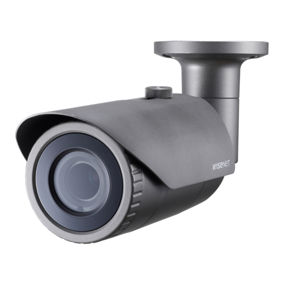
COMPONENT NAMES AND FUNCTIONS Front ➊ ➋ ➌ ➍ ➏ ➎ ➊ Camera Sunshield ➋ Knob Sunshield : Fixing the sunshield onto the camera. ➌ Focus lever : Set focus of lens by turn the focus lever. ➍ Zoom lever : Set zoom magnification of lens by turn the zoom lever. ➎... - Page 12 introduction Back ➐ ➑ ➒ ➐ Function jack BLUE (ALARM OUT) : Output port that signals when a motion is detected. BLACK(GND) : Earth-grounding port for external signal. ➑ Video output jack : Video signals are output through this port. Connect this port to the Video IN port of a AHD DVR.
- Page 13 ADJUST THE LENS’S ZOOM AND FOCUS Remove the sunshield from the camera. Remove the front cover from the camera by turning it counterclockwise. Unlock the Zoom or Focus lever before adjusting the lens. Adjust the zoom & focus by moving the lever counterclockwise for (NEAR & WIDE) and clockwise for (TELE &...
-
Page 14: Connection
CONNECTING TO MONITOR Please connect the Video output jack located on the back of the camera to the AHD DVR. SCO-6083R AHD DVR Monitor As the connecting method varies with the instruments, refer to the manual supplied with the instrument. -
Page 15: Using Coaxial Communications
When the resistance value of copper wire is at [20°C(68°F)] Copper wire size (AWG) #24 (0.22mm #22 (0.33mm #20 (0.52mm #18 (0.83mm Resistance value(—/m) 0.078 0.050 0.030 0.018 Voltage Drop (V/m) 0.028 0.018 0.011 0.006 As shown in the table above, voltage decreases as the wire gets longer. Therefore use of an excessively long adaptor output line for connection to the camera may affect the performance of the camera. - Page 16 connection Video Cable The camera's video output port is connected to the DVR with a BNC coaxial cable, shown below. Recommended Cable Distance Specification 500m 75-5 Coaxial Cable It is recommended that pure copper coax cable is used and not copper coated steel, as this will cause issues with the communication over the coaxial cable.
-
Page 17: Camera Operation
camera operation MENU CONFIGURATION MAIN SETUP ● ● ● BASIC DAY/NIGHT BACKLIGHT PROFILE ● ● ● INDOOR USER ● ● D-WDR ● ● ● OUTDOOR INDOOR WHITE BAL ● ● AWC MANUAL ● ● ● BRIGHTNESS LENS SHUTTER EXPOSURE ● ●... - Page 18 camera operation MAIN SETUP Select the function 1. PROFILE BASIC Change the status using the Function using the Function 2. D-WDR Setup switch. Setup switch. 3. WHITE BAL 4. EXPOSURE 5. BACKLIGHT 6. SPECIAL 7. EXIT SAVE Press the Function Setup switch. Main SETUP menu is displayed on the monitor screen.
- Page 19 INDOOR : It will be set automatically to help you take a picture in a regular indoor lighting condition. USER : Automatically confi gures the camera to your custom settings. Select Custom for Simple Setup mode. Configure the menu options to your custom settings. The settings are automatically saved as Custom mode.
- Page 20 camera operation In D-WDR mode, there can be noise between a bright and dark area. Depending on light conditions, unnatural changes or symptoms can occur on the screen so deactivate the user mode. White Bal (White Balance) Use the White Balance function to adjust the screen color. When the SETUP menu screen is displayed, select ‘White Bal’...
- Page 21 White Balance may not work properly under the following conditions. In this case select the AWC mode. ➊ Select this When the color temperature of environment surrounding the subject is out of the control range (e.g. clear sky, or sunset) ➋...
- Page 22 camera operation The greater the shutter value the brighter the screen is but the more the residual images of objects there are. If the min shutter value is large, it can cause noise, spots and white areas but still operate normally. ...
- Page 23 HLC (High Light Compensation) : HLC SETUP This function masks the strong light LEVEL MIDDLE to minimize white out due to over LIMIT NIGHT ONLY exposure and preserve much of the IIIIIIIIII IIIIIIIIII on-screen details when the camera BOTTOM IIIIIIIIII IIIIIIIIII aims a strong light source.
- Page 24 camera operation SPECIAL When the SETUP menu screen is displayed, select ‘SPECIAL’ by using the Function Setup switch so that the arrow indicates ‘SPECIAL’. Select a desired mode using the SPECIAL SETUP Function Setup switch. DISPLAY COMM ADJ DISPLAY IMAGE ADJ ❶...
- Page 25 FONT COLOR : You can change the OSD font color. (White, Yellow, Green, Red, Blue) LANGUAGE : You can select the menu language according to your requirements. RETURN : Return to the SPECIAL menu. COMM ADJ (Communication Adjustment) : COAX : You can select whether to COMM SETUP use COAX communication.
- Page 26 camera operation VIDEO OUTPUT ❶ If the SPECIAL menu screen is displayed, use the Function Setup switch so that the arrow indicates ‘VIDEO OUTPUT’. ❷ Select a desired mode using the Function Setup switch. HD : HD Video resolution(1920X1080) SD : SD Video resolution ...
- Page 27 DEFOG : You can use the defog mode to allow the camera to automatically detect the fog density of the screen and display a clear image despite smog, fog or general poor visibility. ❶ If the SPECIAL menu screen is DEFOG displayed, use the Function Setup LEVEL...
- Page 28 camera operation MOTION : This product generates signals each time an object movement is detected in the four areas of the screen so efficient monitoring can be achieved. ❶ If the SPECIAL menu screen MOTION DET is displayed, use the Function AREA 1.
-
Page 29: Troubleshooting
troubleshooting TROUBLESHOOTING If you have trouble operating your camera, refer to the following table. If the guidelines do not enable you to solve the problem, contact an authorized technician. Problems Troubleshooting Nothing appears on the screen. Check that the power cord and line connection between the camera and monitor are properly connected. -
Page 30: Specifications
specifications SPECIFICATIONS SCO-6083RN SCO-6083RP Video Imaging Device 1/2.9” 2M CMOS Total Pixels 2,000(H) x 1,121(V) 2.24M pixels Effective Pixels 1,984(H) x 1,105(V) 2.19M pixels Scanning System Progressive Scan Horizontal Resolution 1000TVL Color : 0.2Lux (F1.4, 50IRE); 0.11Lux (F1.4, 30IRE) Min. Illumination B/W : 0Lux(IR LED on) S / N Ratio 52dB (AGC off, Weight on) - Page 31 SCO-6083RN SCO-6083RP Defog AUTO / MANUAL / OFF Motion Detection Off / On(4 zones) Privacy Masking Off / On (4 zones rectangle) Gain Control Off / Low / Middle / High / Very High White Balance ATW / Outdoor / Indoor / Manual / AWC(1,800K° ~ 10,500K°) Electronic Shutter 1 sec ~ 1/12,000 sec Speed...
-
Page 32: Dimension
DIMENSION Unit: mm(inch) 32_ specifi cations... - Page 33 MEMO...
- Page 34 6, Pangyo-ro 319beon-gil, Bundang-gu, Seongnam-si, Gyeonggi-do, SEOUL 463-400 Rep. of KOREA Tel : +82-70-7147-8753, 8764 Fax : +82-31-8018-3740 www.samsungsecurity.com SAMSUNG TECHWIN AMERICA Inc. SAMSUNG TECHWIN EUROPE LTD. 100 Challenger Rd. Suite 700 Ridgefield Park, NJ 07660 2nd Floor, No. 5 The Heights, Brooklands, Weybridge, Surrey,...