
Related Manuals for HUSTLER Z XR7


Summary of Contents for HUSTLER Z XR7
- Page 1 Hustler Z XR7 Parts Manual ••••••• Hustler Turf Equipment ••••• P.O. Box 7000 ••• Hesston, Kansas • 67062-2097...
- Page 2 WARNING: The engine exhaust from this product contains chemicals known to the State of California to cause cancer, birth defects or other reproductive harm. IMPORTANT: This engine is not equipped with a spark arrester muffler. It is a violation of California Public Resource Code Section 4442 to use or operate this engine on any forest-covered, brush-covered, or grass-covered unimproved land.
-
Page 3: Table Of Contents
Chapter 1 General Information ........1-1 Chapter 2 Rivet Nut Installation . - Page 4 Chapter 10 Maintenance & Adjustment Safety ......10-3 Safe Maintenance & Adjustment Practices ....10-4 Maintenance .
-
Page 5: General Information
General Information This Manual covers Hustler XR7 Z models 927723, 927731, 927749, 927756, 927772, 927798, 927806, 927814 with serial numbers prior to 07020000. Frequently Ordered Parts PART NO. 027912 Lubrizol 7 oz. Bottle 027920 Lubrizol 10 oz. Bottle 768341 Hydraulic Oil Filter 781443 Pump Drive Belt 797696... -
Page 6: Standard Torques
your Hustler dealer for current information and parts. Hardware Description Codes & Abbreviations The following codes are used throughout this parts manual. Refer to this list when ordering parts. ABBREVIATION FDRW Standard Torques The following chart lists the standard torque values for the threaded fasteners found in this manual. Torque all cap screws, nuts and set screws to these values unless a different torque is shown in the Notes section next to the fastener. - Page 7 Chapter 2 Contents Rivet Nut Installation ........2-2 Footrest Assembly .
-
Page 8: Rivet Nut Installation
Rivet Nut Installation SERVICE INDEX NO. PART NO. 548032 547760 547752 547950 1. Seat support 547950 includes rivet nuts. MFG. PART QTY. 107701 TRACTOR FRAME (54") 106211 TRACTOR FRAME (60") 106039 TRACTOR FRAME (66") 808493 3/8-16 THREAD RIVET NUT 600961 1/2-13 THREAD RIVET NUT 808477 1/4-20 THREAD RIVET NUT (KAW ONLY) -
Page 9: Footrest Assembly
Footrest Assembly INDEX SERVICE PART NO. 359547 395533 305615 086660 767954 781880 052860 1. Do not tighten, Item 2 (348276 Floor) must be able to pivot on these bolts. 106567 4/07 MFG. DESCRIPTION PART NO. 359547 STEP TREAD 395533 FLOOR 305615 PLATFORM STEP TREAD 086660... - Page 10 106567 4/07...
- Page 11 Chapter 3 Contents Hydraulic System Installation....... 3-2 106567 4/07...
-
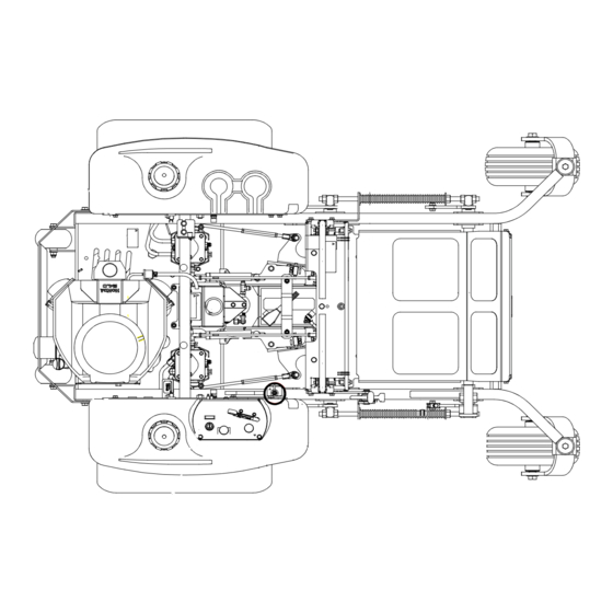
Page 12: Hydraulic System Installation
Hydraulic System Installation FRONT 106567 4/07... - Page 13 Hydraulic System Installation ITEM SERVICE PART NO. 768515 055947 032771 032763 349860 034272 768523 781062 781047 041707 704742 781054 705186 768341 768333 781575 763946 778985 781591 779132 781559 781542 781658 781526 781500 781492 781484 781476 781534 781518 763953 1. Add 3.5 oz. Lubrizol® (027912) when hydraulic oil is changed (see Owner’s Manual).
- Page 14 HYDRAULIC SYSTEM CHARGING PROCEDURE 1. Set handles in the neutral position. 2. Start engine at idle. 3. Let run for a minimum of 30 seconds. 4. Stroke handles to forward position. 5. If motors do not turn in 15 seconds return handles to neutral and repeat step 3 and 4 (one time).
- Page 15 Chapter 4 Contents Battery Installation ........4-2 Deck Lift Assembly .
-
Page 16: Battery Installation
Battery Installation TRACTOR FRAME 106567 4/07... - Page 17 Battery Installation INDEX SERVICE PART NO. 024927 771428 796219 744276 768523 058776 348417 055939 029868 740696 034272 779850 1. When performing service on mower, disconnect battery ground cable and do not reconnect to battery until engine is ready to be started. See Owners Manual.
-
Page 18: Deck Lift Assembly
Deck Lift Assembly TRACTOR FRAME 106567 4/07... - Page 19 Deck Lift Assembly ITEM SERVICE PART NO. 348318 600437 348284 783001 704643 781294 782995 781229 055749 348391 015495 034272 756270 348458 781831 1. Apply grease to zerks (see owner’s manual). 2. Verify pin diameter prior to ordering replacement part. For mowers with 3/8"...
-
Page 20: Steering And Park Brake Assembly
Steering and Park Brake Assembly 11 12 TRACTOR FRAME 106567 4/07... - Page 21 Steering and Park Brake Assembly ITEM SERVICE PART NO. 781260 348755 767954 036244 705178 041152 768523 348946 348888 348714 055822 781716 053199 348987 348862 086660 781583 063198 781211 781286 600221 783696 781922 704163 768515 068551 367557 348797 781153 005116 054502 034272 781765 781112...
- Page 22 NOTES: 1. Torque to 350-375 ft.-lbs. Included with wheel motor. 2. Torque brake assembly mounting bolts to 100 ft.-lbs. 3. 781112 used on left wheel. 4. 781351 used on right wheel. 5. Includes Item 1 (781260 Steering Bar Grip). 6. Use 783696 on mowers with serial numbers prior to 06071499. 106567 4/07...
- Page 23 This page intentionally left blank. 1065674/07...
-
Page 24: Pump Belt And Pulleys Installation
Pump Belt and Pulleys Installation TRACTOR FRAME 4-10 106567 4/07... - Page 25 Pump Belt and Pulleys Installation INDEX SERVICE PART NO. 779876 212076 787366 783829 785659 083196 768127 325308 008193 767962 016527 366765 784918 349761 015495 025296 061101 781856 028118 794446 781302 781443 791251 036236 768523 034272 1. Torque to 45-48 ft-lbs. 2.
- Page 26 4-12 106567 4/07...
- Page 27 Chapter 5 Contents Kawasaki Engine Installation ....... 5-2 Honda Engine Installation ....... . . 5-6 Kohler Engine Installation .
-
Page 28: Kawasaki Engine Installation
Kawasaki Engine Installation TO ENGINE PART OF SENSOR ENGINE YELLOW TO SPADE TERMINAL TO BULLET TERMINALS RED/BLK PURPLE POSITIVE BATTERY CABLE TRACTOR FRAME STARTER SOLENOID GROUND NEGATIVE BATTERY CABLE PART OF COMMON WIRE HARNESS 106567 4/07... - Page 29 Kawasaki Engine Installation ITEM SERVICE PART NO. 777656 782318 058776 768523 029876 792762 768515 024927 799312 799320 044255 030817 055947 792192 771428 050161 786673 057661 788943 785741 034272 782763 366443 036236 786038 796524 350371 349704 767962 016527 064006 781732 781724 720177 782649 782664...
- Page 30 1. Includes mounting hardware. 2. Part of Item 8 (799312 Wire Harness Adapter). 3. Engine oil capacity; 2 US quarts (w/filter). 4. Engine RPM to be set at 3600± 50. 5. 23 HP engine used in 927723 and 927731 only. 6.
- Page 31 This page intentionally left blank. 106567 4/07...
-
Page 32: Honda Engine Installation
Honda Engine Installation PART OF ENGINE NEGATIVE BATTERY CABLE RED/BLK PART OF COMMON WIRE HARNESS TRACTOR FRAME GRA/PUR POSITIVE BATTERY CABLE 106567 4/07... - Page 33 Honda Engine Installation ITEM SERVICE PART NO. 785014 058776 768523 799320 029876 077545 017004 799304 050161 775353 057661 785741 034272 782763 366443 036236 785675 787689 787713 382168 377994 365742 767962 016527 017038 024927 785477 768515 056077 784843 720177 785378 785543 782664 784959 789131...
- Page 34 7. Includes one (1) of Item 14 (057661 Hose Clamp). 8. Supplied with engine. 9. When installing lower hose clamp on air cleaner hose, install as low as possible (against carburetor inlet). 10. This connector used for optional hydraulic oil cooler fan. 11.
- Page 35 This page intentionally left blank. 106567 4/07...
-
Page 36: Kohler Engine Installation
Kohler Engine Installation POSITIVE BATTERY CABLE PUR (P/O ENGINE) RED/BLK TRACTOR FRAME NEGATIVE BATTERY CABLE PART OF COMMON WIRE HARNESS 5-10 106567 4/07... - Page 37 Kohler Engine Installation ITEM SERVICE PART NO. PART NO. 788216 788216 799320 799320 058776 058776 768523 768523 029876 029876 050161 050161 786673 786673 057661 057661 788943 788943 782763 782763 785741 785741 034272 034272 366443 366443 036236 036236 795310 795310 796672 796672 787713 787713...
-
Page 38: Fuel System Installation
Fuel System Installation 5-12 106567 4/07... - Page 39 Fuel System Installation ITEM SERVICE PART NO. 779306 793240 793232 000323 106732 055822 712919 036244 767954 045088 797084 347989 016527 767962 015818 015818 015818 015818 015818 000331 1. Torque to 20 ft.-lbs. 2. Supplied with new fuel tank. 3. Fuel tank service part not shown: 106567 4/07 MFG.
-
Page 40: Instrument Panel Assembly
Instrument Panel Assembly FUSE SIZE AND LOCATION RIGHT SIDE FUEL TANK 5-14 106567 4/07... - Page 41 Instrument Panel Assembly ITEM SERVICE PART NO. 776476 785808 045898 785030 786657 712257 000430 704932 714998 059832 769166 778365 055947 768515 106633 026237 762195 1. Part of 799320 (Common Wire Harness) 106567 4/07 MFG. DESCRIPTION PART NO. 776476 PTO SWITCH 785808 IGNITION KEY SET 045898...
-
Page 42: Electrical Schematic (799320)
Electrical Schematic (799320) 5-16 106567 4/07... - Page 43 Chapter 6 Contents Front Wheel Assembly........6-2 Front Wheel Breakdown—747782.
-
Page 44: Front Wheel Assembly
Front Wheel Assembly TRACTOR FRAME 106567 4/07... - Page 45 Front Wheel Assembly INDEX SERVICE PART NO. 705954 344267 712976 784223 387035 045765 349266 041475 025296 061101 747782 789537 1. Apply grease to zerks. 2. Torque to 100 ft.-lbs. 3. Assemble with extended inner race toward item 5 (387035 Spacer, 1.07 x 1.312 x 2.793).
-
Page 46: Front Wheel Breakdown-747782
Front Wheel Breakdown—747782 ITEM SERVICE PART NO. 039677 747741 747832 782771 019521 015511 1. Inflate tire to 8-10 psi. MFG. DESCRIPTION PART NO. WHEEL BEARING 13 X 6.50 TIRE 6 X 4.5 WHEEL BEARING SPACER TIRE VALVE GREASE FITTING 45 DEG 1/4 NOTES: 106567 4/07... -
Page 47: Optional Semi-Pneumatic Tire/Wheel-789537
Optional Semi-Pneumatic Tire/Wheel—789537 ITEM SERVICE PART NO. 039677 789537 015511 782771 1065674/07 MFG. DESCRIPTION PART NO. WHEEL BEARING TIRE/WHEEL ASSEMBLY GREASE FITTING 45 DEG 1/4 BEARING SPACER NOTES:... -
Page 48: Drive Wheel Assembly Installation
Drive Wheel Assembly Installation INDEX SERVICE PART NO. 784058 781245 784066 019521 061077 770859 781237 781245 781252 019521 061077 770859 1. Torque to 65-75 ft. lbs. 2. Inflate tire to 8-10 psi. PART NO. 784058 WHEEL & TIRE ASSY FOR 66" (QTY PER TRACTOR) TIRE, 12 X 12 X 24 FOR 66"... -
Page 49: Anti-Rollover Wheel Assembly
Anti-Rollover Wheel Assembly TRACTOR FRAME INDEX SERVICE PART NO. 068239 031997 767962 781567 1. Do not torque, wheel must turn freely. 1065674/07 MFG. DESCRIPTION PART NO. 068239 CS .500-13 X 4.500 HX G5 ZN 031997 ANTI-SCALP WHEEL 767962 FW .531 X 1.063 X .090 SAE HD ZN 781567 NT .50-13 HX LK NY NOTES:... - Page 50 106567 4/07...
- Page 51 Chapter 7 Contents 66" Deck Assembly ........7-2 66"...
-
Page 52: 66" Deck Assembly
66" Deck Assembly Optional Anti-Scalp Wheels 106567 4/07... - Page 53 66" Deck Assembly INDEX SERVICE PART NO. 547737 798694 052860 767954 086660 103010 781708 767962 031997 053199 781567 808485 314104 015495 052860 025395 103713 788166 1. Do not torque, Item 2 (349324 Discharge Chute) must pivot freely. 2. Includes 6 each of items 7 through 10. 3.
-
Page 54: 66" Deck Pulley Assembly
66" Deck Pulley Assembly BELT GUIDE INDEXING 106567 4/07... - Page 55 66" Deck Pulley Assembly ITEM SERVICE PART NO. 797936 025007 347443 028118 781856 797910 600189 600171 373191 781302 350884 786335 103721 103739 016972 781385 792002 016527 752386 798975 705954 767962 768523 058776 212472 796235 798496 798512 798504 782474 029934 783738 1.
-
Page 56: 60" Side Discharge Deck Assembly
60" Side Discharge Deck Assembly 106567 4/07... - Page 57 60" Side Discharge Deck Assembly SERVICE INDEX NO. PART NO. 547745 798694 052860 767954 086660 103010 781708 767962 031997 053199 781567 808485 103184 005116 314104 015495 808493 788166 1. Do not torque, Item 2 (798694 Discharge Chute) must pivot freely. 2.
-
Page 58: 60" Deck Pulley Assembly
60" Deck Pulley Assembly 60" DECK BELT GUIDE INDEXING 106567 4/07... - Page 59 60" Deck Pulley Assembly ITEM SERVICE PART NO. 797720 025007 347443 028118 781856 797910 600189 600171 373191 781302 350884 786335 103192 103200 016972 781385 792002 016527 752386 770842 705954 767962 768523 058776 212472 796235 794685 794230 794214 782474 029934 783738 1.
-
Page 60: 54" Deck Assembly
54" Deck Assembly 7-10 Optional Anti-Scalp Wheels 106567 4/07... - Page 61 54" Deck Assembly SERVICE INDEX NO. PART NO. 548008 798694 052860 767954 086660 103010 781708 767962 053199 781567 031997 015495 314104 005116 103184 025395 103572 788166 1. Do not torque, Item 2 (798694 Discharge Chute) must pivot freely. 2. Includes items 9, 10, 11, and 13. 3.
-
Page 62: 54" Deck Pulley Assembly
54" Deck Pulley Assembly 54" DECK ASSY BELT GUIDE POSITIONING 7-12 106567 4/07... - Page 63 54" Deck Pulley Assembly INDEX SERVICE PART NO. 797928 016972 025007 028118 781385 797910 600189 600171 347443 781856 350884 373191 781302 786335 103986 103994 016527 752386 798967 705954 767962 212472 796235 797696 797712 797704 782474 768523 058776 783738 769257 029934 792002 1.
-
Page 64: Spindle Assembly-796235
Spindle Assembly–796235 INDEX SERVICE PART NO. 077123 766204 034843 012005 600893 796227 1. Install upper bearing with extended inner race up. 2. Install lower bearing with extended inner race down. MFG. QTY. DESCRIPTION PART NO. BEARING W/O COLLAR BLADE SPINDLE BUSHING CAST SPINDLE HOUSING GREASE FITTING BEARING DUST COVER... - Page 65 Chapter 8 Contents Deck Installation ........8-2 Deck Belt Routing and Tensioning .
-
Page 66: Deck Installation
Deck Installation TRACTOR ASSEMBLY DECK ASSEMBLY 106567 4/07... - Page 67 Deck Installation ITEM SERVICE PART NO. 055749 061101 025296 051169 704643 1. 66" Deck installation is shown, 54" and 60" Deck installations are similar. 106567 4/07 MFG. DESCRIPTION PART NO. 055749 CS .437-14 X 1.750 HX G5 ZN 061101 NT .750-10 HX NL ZN 025296 FW .760 X 1.625 X.08 ZN 051169...
-
Page 68: Deck Belt Routing And Tensioning
Deck Belt Routing and Tensioning DECK ASSEMBLY 106567 4/07... - Page 69 NOTES: 1. Spring length after tensioning belt. Measure spring from outside of hook to outside of hook. 2. Route belt as shown. 106567 4/07...
-
Page 70: Seat Installation
Seat Installation 106567 4/07... - Page 71 Seat Installation INDEX SERVICES PART NO. 793661 350041 000331 086660 767954 724716 350421 036244 052860 768523 034272 781880 080358 748756 350462 781617 722199 1. Must pivot freely. 2. Service parts available for Michigan Standard seat; PART NO. 793307 793315 793331 793349 793356 797456...
- Page 72 106567 4/07...
-
Page 73: Tractor Decals
Chapter 9 Contents Tractor Decals–US Version ....... . 9-2 Tractor Decals–CE Version ....... . 9-4 66"... -
Page 74: Tractor Decals
Tractor Decals TOP OF SEAT PAN BOTTOM OF SEAT PAN 106567 4/07... - Page 75 Tractor Decals INDEX SERVICE PART NO. 781427 779280 784702 727008 791830 782136 788968 785188 782128 727016 771436 727172 782573 793588 786426 600899 106567 4/07 MFG. QTY. PART NO. 781427 DECK HEIGHT INDICATOR DECAL 779280 HOT & HYDRAULIC OIL DECAL 784702 INSTRUMENT PANEL DECAL (SEPARATE CHOKE) 727008 HYD PRESSURE DECAL...
-
Page 76: 66" Deck Decals
66" Deck Decals INDEX SERVICE PART NO. 799189 760637 727420 727172 727453 727438 781419 799353 359547 797845 MFG. QTY. DESCRIPTION PART NO. 799189 66" SIDE DISCHARGE DECK ID DECAL 760637 MOWER DECK QUICK REFERENCE DECAL 727420 DEFLECTOR SHIELD DECAL 727172 "MADE IN U.S.A."... -
Page 77: 60" Deck Decals
60" Deck Decals INDEX SERVICE PART NO. 786277 760637 727420 727172 727453 727438 799395 799353 359547 797845 106567 4/07 MFG. QTY. DESCRIPTION PART NO. 786277 60" SIDE DISCHARGE DECK ID DECAL 760637 MOWER DECK QUICK REFERENCE DECAL 727420 DEFLECTOR SHIELD DECAL 727172 "MADE IN U.S.A."... -
Page 78: 54" Deck Decals
54" Deck Decals INDEX SERVICE PART NO. 799171 760637 727420 727172 727453 727438 781419 799353 359547 797845 MFG. QTY. PART NO. 799171 54" SIDE DISCHARGE DECK ID DECAL 760637 MOWER DECK QUICK REFERENCE DECAL 727420 DEFLECTOR SHIELD DECAL 727172 "MADE IN U.S.A." DECAL 727453 BELT &... - Page 79 Chapter 10 Contents Maintenance & Adjustment Safety......10-1 Safe Maintenance & Adjustment Practices ..... . .10-2 Maintenance .
- Page 80 10-2 1065674/07...
-
Page 81: Maintenance & Adjustment Safety
Maintenance & Adjustment Safety This safety alert symbol is used to call attention to a message intended to provide a reasonable degree of PERSONAL SAFETY for operators and other persons during the normal operation and servicing of this equipment. DANGER – denotes immediate hazards which WILL result in severe personal injury or death. WARNING –... -
Page 82: Safe Maintenance & Adjustment Practices
Safe Maintenance & Adjustment Practices ▲ This product is capable of amputating hands and feet and throwing objects. Always follow all safety instructions to avoid serious injury or death. ▲ Unless specifically required, DO NOT have engine running when servicing or making adjustments to tractor. - Page 83 off and remove ignition switch key for maximum safety. Repairs or maintenance requiring engine power should be performed by trained personnel only. ▲ Use a stick or similar instrument to clean under the mower making sure that no part of the body, especially arms and hands are under mower.
- Page 84 Safety and Instruction Decals ▲ Specific safety warning decals are located on the equipment near the immediate areas of potential hazards. These decals should not be removed or obliterated. Replace them if they become non- readable. The following illustrations show the various safety decals that are located on the machine. A brief expla- nation, for those requiring one, is shown to help the operator understand the meanings of these decals.
- Page 85 Do not remove or modify stabilizer wheels or rear engine guard or injury can result. Part Number 771436 Keep engine and pump compart-ment(s) clean (especially in exhaust area) to prevent fire and provide Part Number 788968 maximum engine and hydraulic cooling.
-
Page 86: Maintenance
Maintenance Locator Chart 1a. Engine Oil Fill & Dipstick (Kawasaki & Honda) 1b. Engine Oil Fill & Dipstick (Kohler) 2a. Fuel Filter (Honda & Kawasaki) 2b. Fuel Filter (Kohler) 3. Engine Air Cleaner 4. Engine Oil Drain Plug 5. Battery 6. - Page 87 Maintenance Locator Chart 54" & 66" XR7 deck 1. Deck Pusher Arm Zerks (2) 2. Deck Belt 3. Spindle Housing Zerk (3) 4. Blades 60" XR7 deck FIG. 2 10-9 106567 4/07...
- Page 88 SERVICE AT INTERVALS INDICATED Verify safety start interlock system Visually inspect unit for loose hardware and/or damaged parts Visually inspect tires Check oil level, engine (1) Clean air intake screen (5) Check fuel level Blades - sharpen & securely fastened Discharge chute - securely in place &...
- Page 89 INTRODUCTION Regular maintenance is the best prevention for costly downtime or expensive, premature repair. The following pages contain suggested maintenance information and schedules which the operator should follow on a routine basis. Remain alert for unusual noises, they could be signaling a problem. Visually inspect the machine for any abnormal wear or damage.
- Page 90 Drive wheels ...8-12 psi (55-69 KPa) Gauge wheels...8-12 psi (55-69 KPa) Solid fill tires are not recommended for Hustler turf equipment. On any machine, with solid filled tires, the warranty claim will be denied. WARNING: Explosive separation of a tire and rim can cause serious injury or death.
- Page 91 Electrical system The electrical system is a 12-volt, negative ground. Recommended battery size is a garden tractor BCI group U1R with 225 or better cranking AMP rating. A maintenance-free battery is recommended. Other- wise, follow battery manufacturer’s maintenance, safety, storing and charging specifications. The battery is located under the seat platform FIG.
- Page 92 WARNING: Incorrect battery cable routing could cause damage to the tractor and battery cables. This can cause sparks which can cause a battery gas explosion which will result in personal injury. Always disconnect the negative (black) battery cable before disconnecting the positive (red) cable. Always connect the positive (red) battery cable before connecting the negative (black) cable.
- Page 93 Check oil level in hydraulic system after every 50 hours of operation or weekly, whichever occurs first. Check more often if system appears to be leaking or otherwise malfunctioning. Fluid level should be 1” from top of reservoir. Use only SAE 10W40 SG, SF/CC, CD service motor oil. Change hydraulic system filter element (FIG.
- Page 94 Fuel system DANGER: Observe usual fuel handling precautions: Do not smoke while refueling. Do not fill tank with engine running or while engine is hot. Clean up any gasoline spills. Allow engine to cool before storing machine inside a building. Keep fuel away from open flame or spark and store machine away from open flame or spark if there is fuel in the tank.
- Page 95 Use regular unleaded gasoline with an octane rating of 87 or higher. The fuel filter (FIG. 8) is installed in the fuel line between fuel tanks and engine fuel pump. Replace filter annually or after every 500 hours of operation, whichever occurs first. When replacing the fuel filter, check the fuel line hoses and fuel shut-off valve grommet for any cracks or leaks.
- Page 96 The oil drain and oil filter are located at the rear of the engine FIG. 10. ENGINE OIL FILLER TUBE ENGINE OIL FILTER Engine air filter Perform engine air filter maintenance per the scheduled maintenance chart. See “SERVICE AT INTERVALS INDICATED” on page 10. A specially designed dry filter is standard equipment on the Hustler Z and Super Z tractors and supplies clean combustion air to the engine FIG.
- Page 97 (especially diesel engines). Therefore, Hustler Turf Equipment and the engine manufacturers have carefully selected a reliable filter designed to fit the needs of the engines. The filter specified is a Donaldson filter, Hustler part number 785261.
- Page 98 Recommended service procedure 1. Release clamps and remove element. Clean the canister with a damp cloth. 2. Before installing a new element, inspect it by placing a bright light inside and rotate the element slowly, looking for any holes or tears in the paper. Also check gaskets for cuts or tears. Do not attempt to use a damaged element which will allow abrasive particles to enter the engine.
- Page 99 VIEWED FROM BOTTOM OF UNIT 1. Pump belt 2. Engine pulley 3. Pump idler pulley 4. Pump idler arm 5. Pump pulley 6. Electric deck clutch 7. Pump idler spring FIG. 13 Deck Belt Drive Layout 1. Spindle drive belt 2.
- Page 100 Mower blade maintenance Check the mower blades daily, they are the key to power efficiency and well groomed turf. Keep them sharp, a dull blade will tear rather than cut the grass, leaving a brown ragged top on the grass within a few hours.
- Page 101 Do not sharpen to original pattern (below). It is easier to get a straight cutting edge following the resharpening pattern shown above. Original edge FIG. 16 Warped Blade (Replace) Straight Blade (Replace) Comparison of Warped and Straight Blades Resharpening pat- tern Cutting edge Cutting Plane...
- Page 102 This page intentionally left blank. 10-24 106567 4/07...
-
Page 103: Adjustment
Introduction Your Hustler Z was adjusted before it left the factory and was checked during predelivery setup. However, after start-up and continued use, a certain amount of break-in wear will cause some adjustments to change. Remain alert for unusual noises, they could be signaling a problem. Visually inspect the machine for any abnormal wear or damage. - Page 104 JAM NUT PUMP LINKAGE FIG. 20 If the tractor creeps in the neutral position the control linkage may be adjusted as follows: 1. Raise and block the tractor up so the drive wheels are off of the floor. WARNING: Never work under the machine or attachment unless it is safely supported with jack stands.
- Page 105 pump arms are stopping the forward motion of the control arms, loosen the jam nut on the adjustable stop of the corresponding side and turn the stop (set screw) inward to stop the control levers slightly before the pump bottoms out. Lock in place when the adjustment is correct by re-tightening the jam nut.
- Page 106 Park brake adjustment Occasionally check the park brakes and adjustment using the following method: 1. Position the control levers in the neutral position. Disengage the deck clutch. WARNING: Never work under the machine or attachment unless it is safely supported with jack stands.
- Page 107 8. Rotate the tire and at the same time rotate the turnbuckle to shorten the length of the brake linkage to increase the brake pressure. When you feel the brake begin to engage, stop adjusting the turnbuckle. Re-tighten the jam nuts on the turnbuckle. 9.
- Page 108 TENSION IDLER SPRING CHAIN FIG. 29 Engine RPM setting The Hustler Z is designed so that the engine will run at 3600 rpm static pump load only. At this speed the hydraulic pumps are running at their maximum rated speed. Deck leveling and height adjustment The mower deck has three areas that may need to be checked and adjusted periodically.
- Page 109 4. Set cutting height at 3-1/2" in the height indicator by placing the height adjusting stop in the 3-1/2" hole, and turning the height stop so that the pin side is against the stop handle FIG. 32 5. Clamp the height adjusting stop against the stop handle FIG. 32. This will assure that the height will not move during the setting process.
- Page 110 7. Loosen the two nuts on the front of height indicator so that the foot pedal is free FIG. 8. Start the leveling process on the left front of the tractor. 9. Set the amount of threads protruding on the deck lift rod from the lift block at approximately 1"...
-
Page 111: Index
Numerical Index Part Page Index Part Numbers 000323 5-13 000331 5-13 000430 5-15 005116 7-11 008193 4-11 012005 7-14 015495 4-11 7-11 015511 015818 5-13 016527 4-11 5-11 5-13 7-13 016899 5-11 016972 7-13 017004 017038 018846 019521 024927 025007 7-13 025296 4-11... - Page 112 Part Page 600893 7-14 600899 600961 704163 704643 704742 704932 5-15 705137 5-11 705178 705186 705954 7-13 712257 5-15 712919 5-13 712976 714998 5-15 720177 722199 724716 727008 727016 727172 727420 727438 727453 727756 740696 742684 744276 747303 747741 747782 747832 748756 752386...
- Page 113 Part Page 787366 4-11 787689 787713 5-11 788018 5-11 788026 5-11 788166 7-11 788216 5-11 788943 5-11 788968 789131 5-11 789537 791251 4-11 791830 792002 7-13 792192 792762 793232 5-13 793240 5-13 793273 793307 793315 793331 793349 793356 106567 4/07 Part Page 793588...
- Page 114 Part Page Part Page Part Page 106567 4/07...