Table of Contents
Advertisement
50XT---A
Infinityt 15 SEER Single---Packaged Heat Pump
System With Puron
Single Phase
2 to 5 Nominal Tons (Sizes 24---60)
CAUTION
!
EQUIPMENT OPERATION HAZARD
OAT sensor must be field installed. See Accessory
Installation for more details.
CAUTION
!
EQUIPMENT OPERATION HAZARD
This Infinity unit is designed for use with an Infinity User
Interface.
NOTE:
Read the entire instruction manual before starting the
installation.
TABLE OF CONTENTS
. . . . . . . . . . . . . . . . . . . . . . . . . . . . . . . . . . .
. . . . . . . . . . . . . . . . . . . . . . . . . . . . . . . . . .
. . . . . . . . . . . . . . . . . . . . . . . . . . . . . . . . . . . .
. . . . . . . . . . . . . . . . . . . . . . . . . . . . . . . . .
. . . . . . . . . . . . . . . . . . . . . . . . . . . . . . .
. . . . . . . . . . . . . . . . . . . . . . . . . . . . . . . . . . . . . .
. . . . . . . . . . . . . . . . . . . . . . . . . . . . . . . . . . . . .
. . . . . . . . . . . . . . . . . . . . . . . . . . . . . . . . .
. . . . . . . . . . . . . . . . . . . . . . . . . . . . . . . . .
. . . . . . . . . . . . . . . . . . . . . . . . . . . . . . . . . . . . . .
. . . . . . . . . . . . . . . . . . . . . . . . . . . .
. . . . . . . . . . . . . . . . . . . . . . . . . . . .
. . . . . . . . . . . . . . . . . . . . . . . . . . . . . . . . . . .
. . . . . . . . . . . . . . . . . . . . . . . . . . . . . . . . . . . . .
. . . . . . . . . . . . . . . . . . . . . . . . . . . . . . . . . . . .
. . . . . . . . . . . . . . . . . . . . . . . . . . . . .
. . . . . . . . . . . . . . . . . . . . . . . . . . . . . .
. . . . . . . . . . . . . . . . . . . . . . . . . . . . . .
®
(R---410A) Refrigerant
Installation Instructions
. . . . . . . . . . . . . . . . . . . . . . . . .
. . . . . . . . . . . . . . . . .
. . . . . . . . . . . . . . . . . . . . . . . . . . .
. . . . . . . . . . . . . . . . . . . . . . . . . .
. . . . . . . . . . . . . . . . . . . . . .
. . . . . . . . . . . . . . . . . . . . . . . . .
. . . . . . . . . . . . . . . . . . . . . . . . .
. . . . . . . . . . . . . . . . . . . . . .
. . . . . . . . . . . .
. . . . . . . . . . . . . . . . . . . . .
. . . . . . . . . . . . . .
. . . . . . . . . . . . . . . . . . . . . . . . .
. . . . . .
. . . . . . . . . . .
PAGE
2
2
2- -12
2
2
2
2
2
2
6
6
6
. . . . . . . . . . . . . . . . . . . . . . . . . . . . . . . . . . . . . . . .
6
7
8
8
9
9
9
9
11
11
12
13
13- -20
13
17
20
20
20
20
20
1
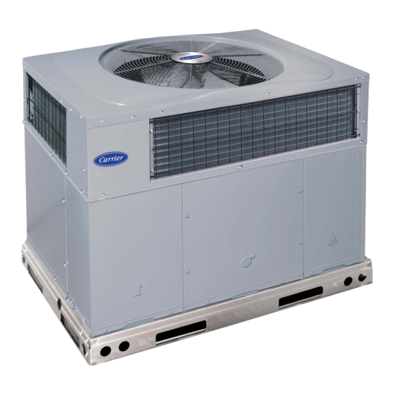
Fig. 1 - - Unit 50XT
. . . . . . . . . . . . . . . . . . . . . . . . . . . . . . . . . . . . .
. . . . . . . . . . . . . . . . . . . . . . . . . . . . .
. . . . . . . . . . . . . . . . . . . .
. . . . . . . . . . . . . . . . . . . . . . . . . . . . . . . .
. . . . . . . . . . . . . . . . . . . . . . . . . . . . . .
. . . . . . . . . . . . . . . . . . . . . . . . . . . . . . . . . . . . .
. . . . . . . . . . . . . . . . . . . . . . .
. . . . . . . . . . . . . . . . . . . . . . . . . . . . . . . . .
. . . . . . . . . . . . . . . . . . . . . . . . . . . . . . . . . . .
®
. . . . . . . . . . . . . . . . . . . . . . . . . . . . . . . . .
. . . . . . . . . . . . . . . . . . . . . . . . . . . .
. . . . . . . . . . . . . . . . . . . . . . . . . . . .
®
. . . . . . . . . . . . . . . . . . . . . . . . . . . . . . . .
. . . . . . . . . . . . . . . . . . . . . . . . . . . . . . . . . . . .
. . . . . . . . . . . . . . . . . . . . . . . . . . . . . . . . .
. . . . . . . . . . . . . . . . . . . . . . . . . .
. . . . . . . . . . . . . . .
. . . . . . . . . . . . . . . . . . . . . . . . . . . . . .
. . . . . . . . . . . . . . . . . . . . . . . . . . . . . . . . . . .
. . . . . . . . . . . . . . . . . . . . . . . .
. . . . . . . . . . . . . . . . . . . . . . . . . . . .
A09032
20
20
20
. . . . . . . . . . . . .
20
. .
20
22- -24
23
23
. . . . .
23
23
23
23
23
. . . . . . . . . . .
23
24
24
24
. . . . . . . .
24
24
24
24
. . . .
24
24
24
25
26
26
29
Advertisement
Table of Contents

Related Manuals for Carrier Infinity 50XT-A


Summary of Contents for Carrier Infinity 50XT-A
-
Page 1: Table Of Contents
50XT---A Infinityt 15 SEER Single---Packaged Heat Pump System With Puron ® (R---410A) Refrigerant Single Phase 2 to 5 Nominal Tons (Sizes 24---60) Installation Instructions CAUTION EQUIPMENT OPERATION HAZARD OAT sensor must be field installed. See Accessory Installation for more details. CAUTION EQUIPMENT OPERATION HAZARD This Infinity unit is designed for use with an Infinity User... -
Page 2: Safety Considerations
Check all items against shipping list. Immediately notify the thoroughly and follow all warnings or cautions included in nearest Carrier office if any item is missing. To prevent loss or literature and attached to the unit. Consult local building codes, the damage, leave all parts in original packages until installation. - Page 3 Dashed lines show cross support HVAC unit HVAC unit location for large basepan units. basepan base rails Sealing Gasket Roofcurb Anchor screw Wood nailer* Flashing field supplied Roofcurb* Insulation (field supplied) Roofing material field supplied Cant strip field supplied COMMON CURB A09096 *Provided with roofcurb A09090...
- Page 4 A09128 Fig. 5 - - 50XT- -A24- -30 Unit Dimensions...
- Page 5 A09129 Fig. 6 - - 50XT- -A36- -60 Unit Dimensions...
-
Page 6: Provide Clearances
Step 3 — Provide Clearances WARNING The required minimum service clearances are shown in Fig. 5 and 6. Adequate ventilation and outdoor air must be provided. The outdoor fan draws air through the outdoor coil and discharges it UNIT FALLING HAZARD through the top fan grille. -
Page 7: Select And Install Ductwork
CAUTION - NOTICE TO RIGGERS PRUDENCE - AVIS AUX MANIPULATEUR ACCESS PANELS MUST BE IN PLACE WHEN RIGGING. PANNEAUX D'ACCES DOIT ÊTRE EN PLACE POUR MANIPULATION. Use top skid as spreader bar. / Utiliser la palette du haut comme barre de répartition DUCTS MINIMUM HEIGHT: 36"... -
Page 8: Converting Horizontal Discharge Units To Downflow (Vertical) Discharge Units
CONVERTING HORIZONTAL DISCHARGE UNITS TO overflowing. Connect a drain tube using a minimum of DOWNFLOW (VERTICAL) DISCHARGE UNITS field- -supplied 3/4 - -in. PVC or field- -supplied 3/4 - -in. copper pipe at outlet end of the 2 - -in. (51 mm) trap (See Fig. 10). Do not WARNING undersize the tube. -
Page 9: Install Electrical Connections
TRAP CAUTION OUTLET 1-in. (25 mm) min. UNIT COMPONENT DAMAGE HAZARD Failure to follow this caution may result in damage to the unit being installed. 2-in. (51 mm) min. 1. Make all electrical connections in accordance with NEC NFPA 70 (latest edition) and local electrical codes governing such wiring. - Page 10 Table 1 – Physical Data - - Unit 50XT- -A UNIT SIZE NOMINAL CAPACITY ton 2--1/2 3--1/2 SHIPPING WEIGHT (lb) (kg) COMPRESSOR Two--Stage Scroll REFRIGERANT (R- -410A) Quantity (lb) 10.3 11.5 14.0 15.5 16.0 (kg) (4.7) (5.2) (4.4) (6.4) (7.0) (7.3) EXPANSION DEVICE- -HEATING AccuRater...
-
Page 11: Routing Control Power Wires
INDOOR THERMOST A T RETURN FROM TOP COVER POWER SOURCE DISCONNECT PER NEC POWER ENTRY CONTROL ENTRY A09091 Fig. 11 - - Typical Installation chassis ground through a printed circuit run at SEC2 and metal GROUND SCREW control board mounting eyelets. Check to be sure control board is (IN SPLICE BOX) mounted securely using both factory- -installed screws. -
Page 12: Special Procedures For 208- -V Operation
NOTE: Mis- -wiring OAT inputs will not cause damage to either HUM output to turn humidifier off. Wire HUM and C terminals directly to humidifier as shown in Fig. 14. Infinity control or thermistor. If the thermistor is wired incorrectly, no reading will appear at UI. -
Page 13: Pre- -Start- -Up
PRE- -START- - UP 6. Each unit system has two Schrader- -type ports, one low- -side Schrader fitting located on the suction line, and WARNING one high- -side Schrader fitting located on the compressor discharge line. Be sure that caps on the ports are tight. START- - UP FIRE, EXPLOSION, ELECTRICAL SHOCK AND ENVIRONMENTAL HAZARD... - Page 14 UTILITY RELAY Liquid Line Solenoid UTILITY SIGNAL OPEN RELAY SUPPLIED BY UTILITY PROVIDER A05247 Fig. 16 - - 2- -Stage HP/AC Control Board B. Control Start- -Up System Communications NOTE: Shorting or mis- -wiring low- -voltage system wiring will Troubleshooting not cause damage to unit control or UI but may cause low voltage fuse to open.
- Page 15 A09092 Fig. 17 - - Wiring Schematic- -50XT- -A Single Phase...
- Page 16 MOTOR TURNS SLOWLY Fan coil control is constantly communicating with the motor, even when the motor and MOTOR LED are off. If motor does not 1. Low static pressure loading of blower while access panel is acknowledge receipt of communications, the fan coil control will removed will cause blower to run slowly.
-
Page 17: Sequence Of Operation
STATUS CODE 36, HEATER OUTPUT NOT SENSED WHEN operation will resume subject to any minimum compressor ENERGIZED off- -delay function which may be in effect. Brownout does not affect blower or electric heater operation. Fan coil control is provided with circuitry to detect presence of a 24- -vac signal on electric heater stage 1 and stage 2 outputs. - Page 18 Table 2 – Heat Pump/Air Conditioner Board Status Codes AMBER FAULT POSSIBLE CAUSE AND ACTION OPERATION FLASH CODE Standby – no call for unit opera- On solid, None Normal operation. tion no flash Rapid, con- Unit being controlled by standard thermostat inputs instead of Infin- Standard Ther- Emergency Mode tinuous...
- Page 19 Fig. 14, 16 and 17). This input allows a power utility device to temperature plus 1_F (- -6°C)or outdoor fan has been ON for 30 interrupt compressor operation during peak load periods. When the minutes. (Fan is turned off to allow refrigerant system to utility sends a signal to shut the system down, the UI will display stabilize.) “Curtailment Active”.
-
Page 20: Check For Refrigerant Leaks
QUIET SHIFT condition exists somewhere in the cooling system, such as insufficient airflow across either coil or both coils. Quiet Shift is a field- -selectable defrost mode which may eliminate occasional noise that could be heard at the start of the defrost cycle REFRIGERANT CHARGE and restarting of the heating cycle. - Page 21 A06297 Fig. 18 - - Non- -Communicating Emergency Cooling/Heating Wiring Connections A09109 Fig. 19 - - Cooling Charging Table- -Subcooling...
-
Page 22: Maintenance
Table 3 – Wet Coil Pressure Drop (in. wc) STANDARD CFM (SCFM) UNIT SIZE 1000 1100 1200 1300 1400 1500 1600 1700 1800 1900 2000 2100 0.005 0.007 0.010 0.012 0.015 – – – – – – – – – –... -
Page 23: Air Filter
Step 1 — Air Filter 3. Inspect the fan blades for cracks or bends. 4. If fan needs to be removed, loosen setscrew and slide fan off IMPORTANT: Never operate the unit without a suitable air filter motor shaft. in the return- -air duct system. Always replace the filter with the 5. -
Page 24: Pressure Switches
Step 9 — Pressure Switches Step 11 — Refrigerant System Pressure switches are protective devices integrated into the control This step covers the refrigerant system of the 50XT- -A, including circuit (low voltage). They shut off compressor if abnormally high the compressor oil needed, servicing systems on roofs containing or low pressures are present in the refrigeration circuit. -
Page 25: Troubleshooting
cylinder in upright position and a commercial metering device in CONTROL FAULT manifold hose. Charge refrigerant into suction line. If the HP/AC control board has failed, the control will flash the TROUBLESHOOTING appropriate fault code (See Table 2). The control board should be replaced. -
Page 26: Final Checks
COMPRESSOR INTERNAL RELIEF If the OAT sensor should fail, low ambient cooling will not be allowed and the one- -minute outdoor fan off delay will not occur. The compressor is protected by an internal pressure relief (IPR) Defrost will be initiated based on coil temperature and time. which relieves discharge gas into compressor shell when differential between suction and discharge pressures exceeds 550 - - If the OCT sensor should fail, low ambient cooling will not be... - Page 27 HEAT PUMP WITH PURON REFRIGERATION SECTION QUICK- - REFERENCE GUIDE Puron refrigerant operates at 50- -70 percent higher pressures than R- -22. Be sure that servicing equipment and replacement components are designed to operate with Puron. Puron refrigerant cylinders are rose colored. S Puron refrigerant cylinders manufactured prior to March 1, 1999, have a dip tube that allows liquid to flow out of cylinder in upright position.
- Page 28 Table 7 – Troubleshooting Chart SYMPTOM CAUSE REMEDY Power failure Call power company Fuse blown or circuit breaker tripped Replace fuse or reset circuit breaker Defective contactor, transformer, HP/AC control board, Replace component or high--pressure, loss--of--charge or low--pressure switch Insufficient line voltage Determine cause and correct Compressor and outdoor fan will not start...
-
Page 29: Start- -Up Checklist
START- -UP CHECKLIST (Remove and Store in Job Files) I. PRELIMINARY INFORMATION MODEL NO.: SERIAL NO.: DATE: TECHNICIAN: II. PRESTART- -UP (Insert check mark in box as each item is completed) ( ) VERIFY THAT ALL PACKING MATERIALS HAVE BEEN REMOVED FROM UNIT ( ) REMOVE ALL SHIPPING HOLD DOWN BOLTS AND BRACKETS PER INSTALLATION INSTRUCTIONS ( ) CHECK ALL ELECTRICAL CONNECTIONS AND TERMINALS FOR TIGHTNESS ( ) CHECK THAT INDOOR (EVAPORATOR) AIR FILTER IS CLEAN AND IN PLACE... - Page 30 Catalog No:50XT ---03SI Copyright 2009 Carrier Corp. D 7310 W. Morris St. D Indianapolis, IN 46231 Printed in U.S.A. Edition Date: 03/09 Manufacturer reserves the right to change, at any time, specifications and designs without notice and without obligations. Replaces: 50XT--- 02SI...