Heatilator ECO-ADV-PS35 Owner's Manual
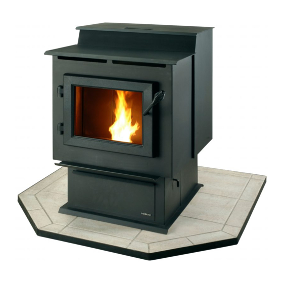
Pellet burning stove
Hide thumbs
Also See for ECO-ADV-PS35:
- Owner's manual (60 pages) ,
- Owner's manual installation and operation (56 pages) ,
- Installation manual (28 pages)
Table of Contents
Advertisement
Models:
ECO-ADV-PS35
ECO-ADV-PS50
ECO-CAB50
Pellet Burning Stove
Service parts list has been removed from this manual.
Refer to Owner's Manual or individual service parts list.
• Important operating and
maintenance instruc-
tions included.
If the information in these instruc-
tions is not followed exactly, a
fi re may result causing property
damage, personal injury, or death.
• Do not store or use gasoline or other fl am-
mable vapors and liquids in the vicinity of
this or any other appliance.
• Do not over fi re - If heater or chimney
connector glows, you are over fi ring. Over
fi ring will void your warranty.
• Comply with all minimum clearances to
combustibles as specifi ed. Failure to
comply may cause house fi re.
WARNING
Fire Risk.
Tested and approved for wood pellets.
Burning of any other type of fuel will void
your warranty.
www.heatilatorecochoice.com
Consumer Care 1-877-427-3316 - Prior to calling, please have the model and serial number of the unit you are calling
about. This information can be found at the rear of the unit.
ECO-ADV-PS35
DO NOT DISCARD THIS MANUAL
Read, understand and
•
follow these instruc-
tions for safe installa-
tion and operation.
WARNING
7058-142L • May 12, 2014
ECO-ADV-PS50
CAUTION
Leave this manual with
•
party responsible for use
and operation.
Hot glass will cause burns.
•
Do not touch glass until it is cooled
•
NEVER allow children to touch glass
•
Keep children away
•
CAREFULLY SUPERVISE children in same room as
fi replace.
•
Alert children and adults to hazards of high
temperatures.
High temperatures may ignite clothing or other
fl ammable materials.
•
Keep clothing, furniture, draperies and other fl ammable
materials away.
Check building codes prior to installation.
• Installation MUST comply with local, regional, state and national
codes and regulations.
• Consult local building, fi re offi cials or authorities having jurisdic-
tion about restrictions, installation inspection, and permits.
Owner's Manual
Installation and Operation
ECO-CAB50
WARNING
HOT SURFACES!
Glass and other surfaces are
hot during operation AND
cool down.
CAUTION
1
Advertisement
Table of Contents
Troubleshooting

Related Manuals for Heatilator ECO-ADV-PS35


Summary of Contents for Heatilator ECO-ADV-PS35
- Page 1 Owner’s Manual Installation and Operation Models: ECO-ADV-PS35 ECO-ADV-PS50 ECO-CAB50 Pellet Burning Stove Service parts list has been removed from this manual. ECO-ADV-PS35 ECO-ADV-PS50 ECO-CAB50 Refer to Owner’s Manual or individual service parts list. CAUTION DO NOT DISCARD THIS MANUAL Read, understand and Leave this manual with •...
-
Page 2: Congratulations
Read this manual before installing or operating this appliance. Please retain this owner’s manual for future reference. Congratulations! Congratulations on selecting a Heatilator pellet burning This owner’s manual should be retained for future refer- appliance. The pellet burning appliance you have selected ence. -
Page 3: Table Of Contents
Safety Alert Key: • DANGER! Indicates a hazardous situation which, if not avoided will result in death or serious injury. • WARNING! Indicates a hazardous situation which, if not avoided could result in death or serious injury. • CAUTION! Indicates a hazardous situation which, if not avoided, could result in minor or moderate injury. •... -
Page 4: Warranty
HEATILATOR ECO-CHOICE WARRANTY Hearth & Home Technologies Inc., on behalf of its hearth brands (“HHT”), extends the following warranty for ECO- CHOICE by heatilator wood and pellet hearth appliances that are purchased from an HHT authorized dealer. WARRANTY COVERAGE: HHT warrantes to the original owner of the HHT appliance at the site of installation, and to any transferree taking own- ership of the appliance at the site of installation within two years following the date of original purchase, that the HHT appliance will be free from defects in materials and workmanship at the time of manufacture. - Page 5 WARRANTY COVERAGE: HHT authorized dealers is available on th HHT branded websites. the nearest HHT authorized dealer or supplier. Additional service fees may apply if you are seeking warranty service from a dealer other than the dealer from whom you originally purchased the product. for parts are not covered by this warranty.
-
Page 6: Section 1: Listing And Code Approvals
Model CAB50: 115 VAC, 60 Hz, Start 5.1 Amps, Run 3.0 Amps this appliance, reserves the right to alter its products, Heatilator is a registered trademark of Hearth & Home their specifi cations and/or price without notice. Technologies. 7058-142L • May 29, 2014... -
Page 7: Section 2: Operating Instructions
User Guide Operating Instructions WARNING HOT SURFACES! Glass and other surfaces are hot during operation AND cool down. Hot glass will cause burns. • DO NOT touch glass until it is cooled • NEVER allow children to touch glass • Keep children away •... -
Page 8: Fire Safety
B. Fire Safety Clinkers To provide reasonable fi re safety, the following should be Minerals and other non-combustible materials such as sand given serious consideration: will turn into a hard, glass-like substance called a clinker when • Install at least one smoke detector on each fl oor of your heated in the fi... -
Page 9: General Operation Information
E. General Operating Information F. Before Your First Fire 1. First, make sure your appliance has been properly 1. Thermostat Calls For Heat installed and that all safety requirements have been met. The appliance is like most modern furnaces; when the Pay particular attention to the fi... -
Page 10: Starting Your First Fire
H. Starting Your First Fire I. Fire Characteristics 1. A thermostat is required for proper operation of this A properly adjusted fi re with the heat output control switch set appliance. If you have to adjust the feed rate after you on “high”... -
Page 11: Ignition Cycles
K. Ignition Cycles L. Clear Space 1. At the beginning of each ignition cycle, it is normal to see WARNING! RISK OF FIRE! Do NOT place combustible some smoke in the fi rebox. The smoke will stop once objects in front or to the sides of the appliance. High tem- the fi... -
Page 12: Section 3: Maintaining & Servicing Appliance A. Proper Shutdown Procedures
Maintaining & Servicing Your Appliance C. General Maintenance A. Proper Shutdown Procedure 1. Types of Fuel CAUTION Depending on the type of fuel you are burning will dictate how often you have to clean your fi repot. Shock and Smoke Hazard If the fuel you are burning has a high dirt or ash content, it may •... - Page 13 3. Ash Removal from Firebox WARNING • Frequency: Weekly or more frequently depending on ash build-up. Fire Risk • By: Homeowner • NEVER pull fi repot cleaning rod out when appliance is operating. a. There must not be any hot ashes in the fi rebox during •...
- Page 14 7. Cleaning the Hopper 5. Disposal of Ashes • Frequency: Monthly or after burning 50 bags of fuel • Frequency: As needed • By: Homeowner • By: Homeowner After burning approximately 50 bags of fuel you will Ashes should be placed in a metal container with a need to clean the hopper to prevent sawdust build-up.
- Page 15 12. Cleaning Convection Blower - Requires No 10. Cleaning the Glass Lubrication • Frequency: When clear view of the fi repot becomes • Frequency: Yearly or more frequently depending on obscure Dust/Dirt build-up • By: Homeowner • By: Homeowner or Qualifi ed Service Technician a.
-
Page 16: High Ash Fuel Content Maintenance
D. High Ash Fuel Content Maintenance • Frequency: As needed • By: Homeowner Pellets Back-up in Feed Tube Poor quality pellet fuel, or lack of maintenance, can create conditions that make the fi repot fi ll quickly with ashes and clinkers. -
Page 17: Frequently Asked Questions
E. Frequently Asked Questions What causes my glass to become dirty? setting. Refer to the Reference Materials section of our If the glass has white ash build up it is normal and the owner’s manual for details. glass should be cleaned. If it is a black soot build up air- fl... -
Page 18: Section 4: Replacement Parts
Figure 18.2. 6. Release blower wires from the nylon wire retainer if applicable. Model ECO-ADV-PS35 has 2 black wires and Model ECO-ADV-PS50 and ECO-CAB50 has 1 black and 1 white wire coming from the blower. -
Page 19: Exhaust Blower
B. Exhaust Blower Replacement 1. Turn down the thermostat, let appliance completely cool and then unplug appliance before servicing. 2. Remove both upper and lower right side curtains. Figure 18.2. on page 18. 3. Disconnect 2 white wires from the white and blue wires of the exhaust blower. -
Page 20: Snap Disc #1, #2, & #3T Replacement
. Snap Disc Replacements Snap Disc #1 - Convection Blower 1. Turn down thermostat, let appliance cool completely if Snap Disc #3 running. Then unplug appliance before servicing. 2. Using #2 Phillips screwdriver, 3/8” wrench, or 3/8” socket loosen the three screws that hold the right upper and lower side panels in place. -
Page 21: Igniter Replacement
D. Igniter Replacement Firepot 1. Shut down the appliance by turning down the thermostat Thermocouple & Thermocouple Cover and let the appliance completely cool down. After the appliance has cooled down, unplug it and remove the ash drawer. 2. The wire leads to the igniter are connected to the wire harness with 1/4 inch male / female spade connectors. -
Page 22: Glass Assembly
F. Glass Replacement WARNING • Glass is 5mm thick high temperature heat- resistant ceramic glass. • DO NOT REPLACE with any other material. • Alternate material may shatter and cause injury. 1. Open the door from the appliance by lifting door off of hinge pins and lay on a fl... -
Page 23: Installer's Guide
Minimum Vacuum MODEL • Installation MUST comply with local, regional, state and Requirements national codes and regulations. ECO-ADV-PS35 .065 inches W.C. • Consult insurance carrier, local building inspector, fi re ECO-ADV-PS50 .075 inches W.C. offi cials or authorities having jurisdiction over restrictions, ECO-CAB50 .075 inches W.C. -
Page 24: Negative Pressure
C. Negative Pressure (Cont’d) D. Thermostat Location - Duct leaks The thermostat’s location will have some affect on the appliance’s operation. To minimize the effects of negative air pressure: When the thermostat is located close to the appliance, it may •... -
Page 25: Tools & Supplies Needed
G. Inspect Appliance & Components F. Tools And Supplies Needed • Remove appliance and components from packaging Tools and building supplies normally required and inspect for damage. for installation, unless installing into an existing • Report to your dealer any parts damaged in shipment. masonry fi... -
Page 26: Section 6: Dimensions & Clearances A. Appliance Dimensions
Dimensions and Clearances MODEL: ECO-ADV-PS35 A. Appliance Dimensions 22-1/4 in. (565mm) 8-3/4 in. 2-3/8 in. (223mm) (60mm) 35-3/4 in. (908mm) 22-15/16 in . 32 in. (583mm) (813mm) 24-13/16 in. (630mm) 20-1/4 in. (514mm) Figure 26.1 - Top View Figure 26.2- Front View... - Page 27 MODEL: ECO-ADV-PS50 A. Appliance Dimensions (Cont’d) 24-1/4 in. (616mm) 9-3/4 in. 2-3/8 in. (248mm) (60mm) 35-3/4 in. (908mm) 32 in. (813mm) 26-7/16 in. (672mm) 28-5/16 in. (719mm) 20-1/4 in. (514mm) Figure 27.1 - Top View Figure 27.2- Front View 4-3/8 in (111mm) 3-1/8 in (79mm) 31-7/8 in (810mm)
-
Page 28: A. Appliance Dimensions
MODEL: ECO-CAB50 A. Appliance Dimensions (Cont’d) 2-3/8 in 23-3/4 in [603 mm] [60 mm] 36-1/2 in [927 mm] 24-1/2 in [622 mm] Figure 28.1 - Top View Figure 28.2- Front View 25-7/8 in [657 mm] 4-3/8 in [111 mm] 3-1/8 in [79 mm] 30-1/8 in [765 mm] 28 in... -
Page 29: Clearances To Combustibles
B. Clearances to Combustibles (UL and ULC) Installations Into Alcove All minimums listed are to a combustible surface. Minimum Maximum Model: PS35 Inches Millimeters Inches Millimeters Height 51-3/4 1314 Width 50-1/4 1276 Depth 1219 Side Wall Straight Back Against Wall Inches Millimeters Mantle Depth... -
Page 30: Alcove
C. Alcove Mantel Figure 30.1 All minimums listed are to a combustible surface. Minimum Maximum Minimum Maximum Model: PS35 Model: CAB50 Inches Millimeters Inches Millimeters Inches Millimeters Inches Millimeters Height 51-3/4 1314 Height 56-3/4 1441 Width 50-1/4 1276 Width 1346 Depth 1219 Depth... -
Page 31: Hearth Pad Requirements
D. Hearth Pad Requirements (UL and ULC) Use a non-combustible fl oor protector, extending beneath appliance and to the front, sides and rear as indicated. Measure front distance “M” from the surface of the glass door. Must extend 2 inches (51mm) beyond each side of pipe (shaded area) Figure 31.2 Figure 31.1... -
Page 32: Section 7: Vent Information
Vent Information B. Venting Termination Requirements A. Chimney and Exhaust Connection CAUTION Chimney & Connector: Use 3 or 4 inch (76-102mm) Do not terminate vent in any enclosed or semi-enclosed area such as a carport, garage, attic, crawl space, under a diameter type "L"... -
Page 33: Pellet Venting Charts
C. Pellet Venting Charts WARNING The maximum horizontal venting allowed with no vertical vent- Fire Risk. ing attached is 48 inches (1219mm) including one 90° elbow or two 45° elbows. This is our recommended horizontal vent- • Only LISTED venting components may be ing installation. -
Page 34: Section 8: Venting Systems
Venting Systems B. Through The Wall & Vertical - External A. Vertical - Interior - Typical Installation PREFERRED METHOD #2 PREFERRED METHOD #1 Rain Cap Rain Cap 12 in. Flashing (305mm) 12 in. Flashing Minimum (305mm) Minimum Firestop 2 in. (51mm) Minimum Support Bracket 6 in. -
Page 35: Masonry
WARNING WARNING Fire Risk Improper installation, adjustment, alteration, service or Inspection of Chimney: maintenance can cause injury or property damage. Refer • Masonry chimney must be in good condition. to the owner’s information manual provided with this appli- • Meets minimum standard of NFPA 211 ance. -
Page 36: Through The Wall
F. Through The Wall Horizontal termination cap must be a minimum of 6 inches. In Canada, where passage through a wall or partition (152mm) from the wall. Approved for mobile home instal- of combustible construction is desired, the installation lations. Must use 3 or 4 inch (76-102mm) “L” or “PL” listed shall conform to CAN/CSA-B365 pellet venting or Listed double wall pipe and an authorized Outside Air Kit in mobile homes. -
Page 37: Section 9: Mobile Home Installation
Mobile Home A. Mobile Home Installation CAUTION You must use an authorized Outside Air Kit THE STRUCTURAL INTEGRITY OF THE MOBILE HOME for installation in a mobile home. FLOOR, WALL AND CEILING/ROOF MUST BE MAIN- TAINED An outside air inlet must be provided for the combustion Do NOT cut through: air and must remain clear of leaves, debris, ice and/or •... -
Page 38: Section 10: Appliance Set-Up
Appliance Set-Up A. Outside Air Kit Instructions 1. Measure distance from fl oor to air vent opening in appli- ance and mark location on wall. There are two Outside Air Kits that will work with this appli- ance. One kit, 811-0872 uses a 2 inch fl ex hose (included) Use saw to cut opening in wall. -
Page 39: Top Vent Adapter
Silicone Rear Exhaust Outlet B. Top Vent Adapter Installation 3 to 3 inch Top Vent Adapter 3 to 6 inch Offset Adapter 3 to 6 inch Top Vent Offset Adapter Installing the Top Vent Adapter Put a layer of high temperature silicone on the 3 inch (76mm) exhaust outlet. -
Page 40: Thermostat Installation
D. Thermostat Installation CAUTION A low voltage thermostat is required to operate this pellet appliance. You may use the included wall mount Shock hazard. thermostat (Figure 40.2) or purchase an optional pro- • Do NOT remove grounding prong from plug. grammable thermostat or remote control. -
Page 41: Section 11: Troubleshooting
With proper installation, operation, and maintenance your appliance will provide years of trouble-free service. If you do experience a problem, this troubleshooting guide will Troubleshooting assist a qualifi ed service person in the diagnosis of a problem and the corrective action to be taken. -
Page 42: Troubleshooting
Troubleshooting Symptom Possible Cause Corrective Action Slow or smoky start-up Dirty exhaust and/or venting system. Check for ash build up in unit, includ- (Cont’d) ing behind rear panels, fi rebox, exhaust blower and venting. Wet fuel / poor quality fuel Replace fuel Feed system fails to Out of fuel. -
Page 43: Section 11: Troubleshooting
Troubleshooting Symptoms Possible Cause Corrective Action Convection blower fails to #1 snap disc defective. Replace snap disc. start. Blower not plugged in. Check that blower is plugged into wire har- ness. Blower is defective or object jammed in Replace blower. impeller. -
Page 44: Section 12: Reference Materials
Reference Materials A. Component Function When describing the location of a component, it is always AS YOU FACE THE FRONT OF THE 1. Control Box APPLIANCE. a. The control box is located on the lower left side of the appliance, behind the lower left side panel and above 2. - Page 45 grounded and has the correct polarity. A good surge protector it. This snap disc turns the convection blower on and off as is recommended. needed. Power is always present at snap disc #1. 12. Red Call Light 17. Snap Disc #2 (Fuel Delivery Interrupt) 175°F The red call light is on the side of the junction box, below the Snap disc #2 is located on the center of the convection fuse.
-
Page 46: Component Locations
B. Component Locations Back of Appliance Heat Output Switch Terminal Block Center 2 Screws for Thermostat Wires Power Outlet Reset Button Figure 46.1 LOCATED BEHIND RIGHT SIDE PANELS Feed Motor LOCATED BEHIND LEFT SIDE PANELS Control Box Convection Blower Vacuum Switch Fuse Junction Box Combustion Blower... -
Page 47: Service & Maintenance Log
C. Service And Maintenance Log Date of Service Performed By Description of Service Figure 47.1 7058-142L • May 29, 2014... -
Page 48: Contact Information
Hearth & Home Technologies 1445 North Highway Colville, WA 99114 Division of HNI INDUSTRIES Please contact your Heatilator dealer with any questions or concerns. For the number of your nearest Heatilator dealer, please visit www.heatilator.com or www.heatilatorecochoice.com. For Consumer Care 1-877-427-3316 Prior to calling, please have the model and serial number of the unit you are calling about.