Table of Contents
Advertisement
Model:
ECO-NZ-PS35
Pellet Burning Stove
•
Important operating and
maintenance instructions
included.
If the information in these
instructions is not followed exactly,
a fire may result causing property
damage, personal injury, or death.
•
Do not store or use gasoline or other flammable
vapors and liquids in the vicinity of this or any
other appliance.
• Do not over fire - If heater or chimney connector
glows, you are over firing. Over firing will void your
warranty.
• Comply with all minimum clearances to
combustibles as specified. Failure to comply may
cause house fire.
Fire Risk.
Tested and approved for wood pellets. Burning of
any other type of fuel will void your warranty.
www.heatilatorecochoice.com
DO NOT DISCARD THIS MANUAL
• Read, understand and
follow these instructions
for safe installation and
operation.
WARNING
WARNING
Heatilator • ECO-NZ-PS35 • 7072-111B • December 1, 2011
ECO-NZ-PS35
CAUTION
CAUTION
• Leave this manual with
party responsible for use
and operation.
Hot glass will cause burns.
• Do not touch glass until it is cooled
• NEVER allow children to touch glass
• CAREFULLY SUPERVISE children in same room as
fireplace & keep them away from the glass.
• Alert children and adults to hazards of high
temperatures.
High temperatures may ignite clothing or other
flammable materials.
• Keep clothing, furniture, draperies and other flammable
materials away.
Check building codes prior to installation.
• Installation MUST comply with local, regional, state and national codes
and regulations.
• Consult local building, fire officials or authorities having jurisdiction
about restrictions, installation inspection, and permits.
Owner's Manual
Owner's Manual
Installation and Operation
Installation and Operation
WARNING
HOT SURFACES!
Glass and other surfaces are hot
during operation AND cool down.
CAUTION
1
Advertisement
Table of Contents

Related Manuals for Heatilator ECO-NZ-PS35


Summary of Contents for Heatilator ECO-NZ-PS35
- Page 1 High temperatures may ignite clothing or other • Comply with all minimum clearances to flammable materials. combustibles as specified. Failure to comply may • Keep clothing, furniture, draperies and other flammable cause house fire. materials away. WARNING CAUTION Fire Risk. Check building codes prior to installation. • Installation MUST comply with local, regional, state and national codes Tested and approved for wood pellets. Burning of and regulations. any other type of fuel will void your warranty. • Consult local building, fire officials or authorities having jurisdiction about restrictions, installation inspection, and permits. Heatilator • ECO-NZ-PS35 • 7072-111B • December 1, 2011 www.heatilatorecochoice.com...
-
Page 2: Congratulations
.14 x .875” S/N Installation Date: 2011 2012 2013 JAN FEB MAR APR MAY JUN JUL AUG SEP OCT NOV DEC 7072-110 Heatilator • ECO-NZ-PS35 • 7072-111B • December 1, 2011 www.heatilatorecochoice.com TERIAL: NON-ANODIZED ALUMINUM 0.020 THICK CKGROUND: SILVER... -
Page 3: Table Of Contents
Component Locations ....... 34 C. General Maintenance ......12-15 Troubleshooting ........35-37 D. High Ash Fuel Content Maintenance .... 16 Service Parts List ........38-41 Service and Maintennance Log ....42 E. Frequently Asked Questions ......17 Homeowner’s Notes ........43 Replacement Parts 14. Contact Information ........44 A. Convection Blower Replacement ....18 www.heatilatorecochoice.com Heatilator • ECO-NZ-PS35 • 7072-111B • December 1, 2011... -
Page 4: Warranty Coverage
• Check with your dealer in advance for any costs to you when arranging a warranty call. Travel and shipping charges for parts are not covered by this warranty. Warranty Period Warranty coverage begins at the date of installation. In the case of new home construction, warranty coverage begins on the date of first occupancy of the dwelling or six months after the sale of the product by an independent, authorised Switch dealer/distributor, whichever occurs earlier. The warranty period for parts and labour for covered components is produced in the following table. Warranty Period Components Covered Parts Labour 1 Year All parts and material except as covered by Conditions, exclusions and Limitations listed. 3 Years Firepots and Burnpots 3 Years 1 Year Castings 5 Years 3 Years Firebox and heat exchanger 90 Days All replacement parts beyond warranty period See conditions, exclusions and limitations on next page Heatilator • ECO-NZ-PS35 • 7072-111B • December 1, 2011 www.heatilatorecochoice.com... -
Page 5: Warranty Exclusions
• Non Switch approved venting components, hearth components or other accessories used in conjunction with the appliance. • Any part of a pre-existing fireplace system in which an insert or a decorative gas appliance is installed. • Switch/HHT’s obligation under this warranty does not extend to the appliances’ capability to heat the desired space. Information is provided to assist the consumer and the dealer in selecting the proper appliance for the application. Consideration must be given to appliance location and configuration, environmental conditions, insulation and air tightness of the structure. The warranty is void if: • The appliance has been over-fired or operated in atmospheres contaminated by chlorine, fluorine, or other damaging chemicals. Over firing can be identified by, but not limited to, warped plates or tubes, rust coloured cast iron, bubbling, cracking and discoloration of steel or enamel finishes. • The appliance is subjected to prolonged periods of dampness or condensation. • There is any damage to the appliance or other components due to water or weather damage which is the result of, but not limited to, improper chimney or venting installation. The owner’s exclusive remedy and Switch/HHT’s sole obligation under this warranty, under any other warranty, express or implied, or in contract, tort or otherwise, shall be limited to replacement, repair, or refund, as specified above. In no event will Switch/HHT be liable for any incidental or consequential damages caused by defects in the appliance. Some countries do not allow exclusions or limitation of incidental or consequential damages, so these limitations may not apply to you. This warranty gives you specific rights; you may also have other rights, which vary from country to country. EXCEPT TO THE EXTENT PROVIDED BY LAW, SWITCH/HHT MAKES NO EXPRESS WARRANTIES OTHER THAN THE WARRANTY SPECIFIED HEREIN. THE DURATION OF ANY IMPLIED WARRANTY IS LIMITED TO DURATION OF THE EXPRESSED WARRANTY SPECIFIED ABOVE. www.heatilatorecochoice.com Heatilator • ECO-NZ-PS35 • 7072-111B • December 1, 2011... -
Page 6: Specifications
High Medium Mean flue gas temp Mean flue gas temp Mean flue gas temp 189°C 166°C 110°C Fuel consumption Fuel consumption Fuel consumption 1.9kg/hour 1.4kg/hour 0.7kg/hour Heating power output - 7kW Heating power output - 5.2kW Heating power output - 2.7kW Average particulate emissions Average emission rate Average efficiency (dry weight) 25mg/MJ 0.4g/kg Gross Calorific value of pellets Fuel type (dry weight) Wood pellets -6mm Ø - complying with draft 20.1MJ/kg standard AS/NZS4014.6:2008 Heatilator is a registered trademark of Hearth & Home Technologies. Heatilator • ECO-NZ-PS35 • 7072-111B • December 1, 2011 www.heatilatorecochoice.com... -
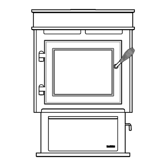
Page 7: User Guide
Pellets Assembly Door Handle Heat Output Switch, Assembly 3 Baffles Reset Button, On/Off switch Firepot Cleaning Rod Firepot & Thermocouple Ash Drawer Figure 1 General Operating Parts The illustration is intended to show an overview of the operating parts for your stove. The appearance of your appliance may vary slightly. For specific part numbers and locations for your model, see the exploded view drawings in the back of the manual. www.heatilatorecochoice.com Heatilator • ECO-NZ-PS35 • 7072-111B • December 1, 2011... -
Page 8: Fire Safety
The fire has two switches on the back of the fire one to warranty. turn the fire on and off the second is the heat output control Fuel Material (see “Figure 2” on page 9). To turn the fire on press the ON/OFF switch to the on position the fire will then go • Made from sawdust or wood by-products through its start-up sequence. • Depending on the source material it may have a high or low ash content. The fires also have the option of a room thermostat, when Higher Ash Content Material the thermostat calls for heat, the fire will automatically light and deliver heat. • Hardwoods with a high mineral content • Fuel that contains bark When the room is up to temperature and the thermostat is • Standard grade pellets or high ash pellets satisfied, the appliance will shut down (not recommended for older drafty houses) Heatilator • ECO-NZ-PS35 • 7072-111B • December 1, 2011 www.heatilatorecochoice.com... -
Page 9: Before Your First Fire
• DO NOT BURN GARBAGE OR FLAMMABLE FLUIDS SUCH AS GASOLINE, NAPHTHA OR ENGINE OIL. • DO NOT USE CHEMICALS OR FLUIDS TO START THE FIRE. Push Bottom of Latch Inward to Release • Keep all such liquids well away from the heater while it is in use. • Combustible materials may ignite. F. Before Your First Fire 1. First, make sure your appliance has been properly installed and that all safety requirements have Figure 4 been met. Pay particular attention to the fire protection and flueing. www.heatilatorecochoice.com Heatilator • ECO-NZ-PS35 • 7072-111B • December 1, 2011... -
Page 10: Starting Your First Fire
8. For your first fire it will be necessary to press the clear and seals are intact. reset button once approximately two minutes after start up and again in five minutes. This will LOCATED BEHIND LEFT SIDE PANELS Control Box Convection Blower Fuse Junction Box Red Call Light Figure 5 Heatilator • ECO-NZ-PS35 • 7072-111B • December 1, 2011 www.heatilatorecochoice.com... -
Page 11: Ignition Cycles
NOTICE: Clearances may only be reduced by means light will come back on. approved by the regulatory authority having jurisdiction. 6. You should see a fire shortly. If not, follow the instructions on page 10, for “Starting Your First Fire”. CAUTION WARNING Fire Risk Odors and vapors released during initial operation. Do NOT operate appliance: • Curing of high temperature paint. • With appliance door open. • Open windows for air circulation. • Firepot floor open. Odors may be irritating to sensitive individuals. Do NOT store fuel: • Closer than required clearances to com- bustibles to appliance • Within space required for loading or ash removal. www.heatilatorecochoice.com Heatilator • ECO-NZ-PS35 • 7072-111B • December 1, 2011... -
Page 12: Maintaining & Servicing Your Appliance
NOTICE: These are recommendations. Clean more frequently if you encounter heavy build-up of ash at the recommended interval or you see soot coming from the vent. Failure to properly clean your appliance on a regular basis will void your warranty. Heatilator • ECO-NZ-PS35 • 7072-111B • December 1, 2011 www.heatilatorecochoice.com... - Page 13 Pull out Ash Drawer & Dispose of painted area visible Ashes in Non-Combustible Container Lift up and push closed Firepot Cleaning Rod Figure 7 CLOSED Position No light colour paint is visible Figure 8 www.heatilatorecochoice.com Heatilator • ECO-NZ-PS35 • 7072-111B • December 1, 2011...
- Page 14 Baffles Removed The venting (chimney) system may need to be cleaned Door Cross Section (example) Latch Cam Locknut Spring Handle Door Handle Spacing Exhaust Path and Drop Tube Washer Square Key Blower Impellers Figure 11 Figure 10 Heatilator • ECO-NZ-PS35 • 7072-111B • December 1, 2011 www.heatilatorecochoice.com...
- Page 15 By: Qualified Service Technician a. Be sure the appliance is allowed to cool, has been d. Be sure the appliance is allowed to cool, has been unplugged and the exhaust blower is off. NOTE: Hearth & Home Technologies recommends to use a heavy duty vacuum cleaners specifically designed for solid fuel appliance cleaning. www.heatilatorecochoice.com Heatilator • ECO-NZ-PS35 • 7072-111B • December 1, 2011...
-
Page 16: High Ash Fuel Content Maintenance
• Failure to do so could result in smoking, sooting and possible Correct Flame Height hopper fires. Yellow/White in Colour CAUTION Odors and vapors released during initial operation. • Curing of high temperature paint. • Open windows for air circulation. Odors may be irritating to sensitive individuals. Figure 15 Heatilator • ECO-NZ-PS35 • 7072-111B • December 1, 2011 www.heatilatorecochoice.com... -
Page 17: Frequently Asked Questions
An inefficient and non-economical method of burning of fuel caused by poor quality pellet fuel is shown in “Figure ISSUES SOLUTIONS Noise is caused by metal expanding and contracting as it heats up and cools down, similar to the sound produced Metallic noise. by a log fire. This noise does not affect the operation or longevity of your appliance. White ash buildup on glass. This is normal. Clean the glass. Excessive build up of ash. See solution #4. The lower burn settings will produce more ash, the higher burn Glass has build-up of black soot. settings produce less. The more it burns on low the more frequent cleaning of the glass is required. The firepot, exhaust blower, exhaust path or baffles Fire has tall flames with black tails and is lazy. needs cleaning. The firepot is dirty. Check the air holes have not been Smokey start-up or puffs of smoke from the airwash. blocked with clinker this can be removed using the supplied tool This is normal. Flame will settle down once the fire is Large flame at start-up. established. Rumbling sound. Make sure the ash drawer is completely closed. www.heatilatorecochoice.com Heatilator • ECO-NZ-PS35 • 7072-111B • December 1, 2011... -
Page 18: Replacement Parts
Figure 18 8. Return wires to nylon wire retainer. Make sure wires do Loosen Screws, not contact any Do Not Remove moving parts or touch any surfaces that Hold Down Bracket may become Spade hot “Figure Connectors 19”. Locating Tab Figure 16 Figure 19 Heatilator • ECO-NZ-PS35 • 7072-111B • December 1, 2011 www.heatilatorecochoice.com... -
Page 19: Exhaust Blower Replacement
Snap Disc #3 (if applicable), let appliance cool completely if the feed motor. “Figure running. Then unplug appliance before servicing. 21”. 2. Using #2 Phillips screwdriver, 3/8” wrench, or 3/8” It has two gray socket loosen the three screws that hold the right wires attached to it with Snap Disc #1 upper and lower side panels in place. You do not 1/4 inch female spade need to remove the screws. Remove side panels terminals. by lifting up and out. Snap Disc #2 3. Snap disc #1 is located on the convection plenum below the feed motor. “Figure 21”. Figure 21 www.heatilatorecochoice.com Heatilator • ECO-NZ-PS35 • 7072-111B • December 1, 2011... -
Page 20: Igniter Replacement
Use handle at top of center baffle to pull up wire harness with 1/4 inch male / female spade and then towards you. connectors. 3. Follow the directions on page 18 to remove the upper and lower right side panels to expose the spade connect 4. Disconnect the spade connectors and remove the igniter from the chamber. Loosen thumb screw and slide igniter out. Figure 24 Heatilator • ECO-NZ-PS35 • 7072-111B • December 1, 2011 www.heatilatorecochoice.com... -
Page 21: Glass Replacement
Lift up to remove hooks from slots Remove the 4 brackets outlined in the diagram Figure 25 Figure 27 WARNING Remove right baffle • Glass is 5mm thick high temperature heat- resistant ceramic glass. • DO NOT REPLACE with any other material. • Alternate material may shatter and cause injury. Figure 26 www.heatilatorecochoice.com Heatilator • ECO-NZ-PS35 • 7072-111B • December 1, 2011... -
Page 22: Installer's Guide
Causes include: Considerations for successful draft include: • Exhaust fans (kitchen, bath, etc.) • Preventing negative pressure • Range hoods • Location of appliance and chimney • Combustion air requirements for furnaces, water To measure the draft or negative pressure on your heaters and other combustion appliances appliance use a magnahelic or a digital pressure gauge • Heat transfer kits capable of reading 0 - .25 inches of water column (W.C.). • Clothes dryers The appliance should be running on high for at least 15 • Location of return-air vents to furnace or air conditioning minutes for the test. Heatilator • ECO-NZ-PS35 • 7072-111B • December 1, 2011 www.heatilatorecochoice.com... -
Page 23: Thermostat Location
Outside Air Intake on windward side on leeward side and away from drafts. Figure 30 NOTE: Thermostats are not recommended for old drafty poorly insulted house as the fire may start and stop often www.heatilatorecochoice.com Heatilator • ECO-NZ-PS35 • 7072-111B • December 1, 2011... -
Page 24: Tools And Supplies Needed
• Remove appliance and components from packaging and inspect for damage. A power outlet is available nearby. • Report to your dealer any parts damaged in shipment. • Read all the instructions before starting the installation. Follow these instructions carefully during the installation to ensure maximum safety and benefit. Heatilator • ECO-NZ-PS35 • 7072-111B • December 1, 2011 www.heatilatorecochoice.com... -
Page 25: Dimensions And Clearances
711mm 583mm 630mm 514mm Figure 31 Top View Figure 32 Front View 111mm 79mm 784mm 730mm 247mm 527mm Figure 33 Side View Figure 34 Side View with Top Vent Adapter www.heatilatorecochoice.com Heatilator • ECO-NZ-PS35 • 7072-111B • December 1, 2011... -
Page 26: Hearth Pad Requirements
* from shielded flue Note: AS/NZS 2918 requires a minimum of 100mm clearance for any side requiring access. Note: These are minimum clearances to combustibles. Actual installation distances may be greater. Heatilator • ECO-NZ-PS35 • 7072-111B • December 1, 2011 www.heatilatorecochoice.com... -
Page 27: Flueing Information A. Chimney And Exhaust Connection
Air Kit Shown Switch recommends the use of Davin flu kits as outlined on page 28 and page 29. These have been tested and approved for use with the ECO-CHOICE range of fires if you intend to use a different flue kit you will need to consult Air Intake Channel with your local council (Discard) NOTE: Seal pipe joints with high temperature silicone , or equivalent, (250°C minimum rated only). Do not put sealant inside of pipe. WARNING Vent surfaces get HOT, can cause burns if Figure 36 touched. Non-combustible shielding or guards may be required. www.heatilatorecochoice.com Heatilator • ECO-NZ-PS35 • 7072-111B • December 1, 2011... - Page 28 12. U se wire tie or hose clamp depending on the Outside Air Kit to secure flex pipe to collar assembly. 13. S lide trim ring over flex pipe and run pipe through wall. 14. A ttach flex pipe to outside termination cap with second wire tie or hose clamp. 15. S ecure termination cap to outside surface. 16. S ecure trim ring to interior wall. WARNING Fire Risk. Follow Flue Manufacturer’s Instructions for Proper Installation Maintain minimum clearances to combustibles Heatilator • ECO-NZ-PS35 • 7072-111B • December 1, 2011 www.heatilatorecochoice.com...
-
Page 29: Internal Standard Flue Kit
AS/NZS2918:2001. Drawing representative only - not to scale. December 2006 To order : Telephone 0800 765 431. Fax 64 3 341 8057 info@switchenergy.co.nz www.switchenergy.co.nz www.heatilatorecochoice.com Heatilator • ECO-NZ-PS35 • 7072-111B • December 1, 2011... -
Page 30: External Standard Flue Kit
Drawing representative only - not to scale. instructions and AS/NZS2918:2001. December 2006 To order : Telephone 0800 765 431. Fax 64 3 341 8057 info@switchenergy.co.nz www.switchenergy.co.nz Heatilator • ECO-NZ-PS35 • 7072-111B • December 1, 2011 www.heatilatorecochoice.com... -
Page 31: Reference Materials
To adjust the Magnahelic of the fire you need to adjust the reached a temperature of 200°F (93°C) in the firepot rotary switch setting on the control box. and will turn red when it reaches 600°F (315°C). c. There is also an internal blue light located in the control Do this prior to starting the fire box. When you plug in the appliance the blue light will automatically start blinking. For model PS35 the blue • Unplug / depower the appliance. light should flash 6 times every 10 seconds for the first • Using #2 Phillips screw driver, 3/8” or 10mm wrench 60 seconds after power up. or socket, loosen the three screws that hold the right www.heatilatorecochoice.com Heatilator • ECO-NZ-PS35 • 7072-111B • December 1, 2011... -
Page 32: Convection Blower
15. Vacuum Switch The hopper switch is located in the upper right hand corner of the hopper. This switch is designed to shut down the The vacuum switch is located on the lower right side of the feed motor whenever the hopper lid is opened. appliance behind right side panel. There are two red wires attached to it. This switch turns the feed system on when 9. Igniter vacuum is present in the firebox. The vacuum switch is a safety device to shut off the feed motor if the exhaust or the The igniter is mounted on the base of the firepot. heat exchanger system is dirty or plugged or if the firebox Combustion air travels over the red hot igniter creating door is open. super heated air that ignites the pellets. 16. Wiring Harness See “Figure 38” below. Heatilator • ECO-NZ-PS35 • 7072-111B • December 1, 2011 www.heatilatorecochoice.com... - Page 33 Orange White Blue Snap Convection Black Disc #1 Motor Black Yellow Purple Grey Combustion Blue Blower Black Black Call Reset Light Button Fuse Snap Disc #3 Grey Figure 38 Igniter www.heatilatorecochoice.com Heatilator • ECO-NZ-PS35 • 7072-111B • December 1, 2011...
-
Page 34: Component Locations
LOCATED BEHIND RIGHT SIDE PANELS Feed Motor LOCATED BEHIND LEFT SIDE PANELS Control Box Convection Blower Vacuum Switch Fuse Combustion Blower Junction Box Red Call Light Figure 40 Figure 41 Heatilator • ECO-NZ-PS35 • 7072-111B • December 1, 2011 www.heatilatorecochoice.com... -
Page 35: Troubleshooting
Call light on. No fire. Firepot is dirty. Clean firepot. Make sure there is not a clinker in Unburned pellets in the firepot. Clinkers may have to be pushed out of firepot. firepot with firepot clean-out tool or other means. Clear igniter chamber using firepot clean-out tool. Igniter chamber blocked. Remove ash drawer to see if igniter is glowing red Igniter not working. on start-up. Check igniter wires for good connection. Use a multimeter to check igniter for continuity. Replace igniter using instructions in manual. Replace control box. Control box defective. Firepot floor open. Slow or smoky start-up. Firepot is dirty. Clean firepot. Make sure there is not a clinker in the firepot. Clinkers may have to pushed out of Igniter chamber blocked. firepot with firepot clean-out tool or other means. Firepot floor partially open. Check if firepot floor is closed all the way Reduce feed rate using feed rate adjustment con- trol rod located inside hopper. Close firepot floor. Excessive amount of fuel at start-up. Clear igniter chamber using firepot clean-out tool. www.heatilatorecochoice.com Heatilator • ECO-NZ-PS35 • 7072-111B • December 1, 2011... - Page 36 Reset snap disc or replace if defective. sequence. Snap disc #3 tripped or defective. Connect to power. No power. Replace fuse. Fuse blown. Check connections at thermostat and appliance. Tempo- Connections at thermostat and/or appliance not rarily jump connection to verify making proper contact. Replace thermostat or wiring. NOTE: To test thermostat and wiring, use a jumper wire at the thermostat block on the unit to by-pass thermostat Defective thermostat or thermostat wiring. and wiring. Replace control box. Control box defective. Unit fails to shut off. Call light on. Turn thermostat off. If call light does not go out, disconnect thermostat wires from unit. If call light does go out, thermostat or wires are defective. Heatilator • ECO-NZ-PS35 • 7072-111B • December 1, 2011 www.heatilatorecochoice.com...
- Page 37 Clean hopper, see page 14. Feed motor is reversing. Check for good connections between feed motor and wire harness. Feed motor is weak Test feed motor torque. Feed bearing adjustment Adjust feed bearing Defective thermocouple. Replace thermocouple. Defective control box. Replace control box. Firepot more than 1/2 full. See page 16 for detailed instructions for “High Ash Fuel Content Management” Reduce feed rate Appliance calls for heat. Thermocouple is defective or not properly Check connections on thermocouple or replace if Call light illuminates. plugged in. defective. Exhaust blower starts. A flashing yellow light on the control box indicates No feed or igniter. a problem with the thermocouple. Defective control box Replace control box. www.heatilatorecochoice.com Heatilator • ECO-NZ-PS35 • 7072-111B • December 1, 2011...
-
Page 38: Service Parts List
ECO-NZ-PS35 Service Parts Beginning Manufacturing Date: Dec 2011 Free Standing Pellet Stove Ending Manufacturing Date: Active Part number list on following page. 12/11 Heatilator • ECO-NZ-PS35 • 7072-111B • December 1, 2011 www.heatilatorecochoice.com... - Page 39 Pull Rod SRV7058-141 Igniter (Loop), 220V 812-3901 Wing thumb Screw 8-32 x 1/2 7000-223/24 Ash Pan Assembly SRV7058-013 Heatilator Logo 4021-049 Pedestal Side Qty 2 req SRV7058-153 Blower, Convection 230V SRV7000-630 Wire Harness SRV7072-112 Fuse 7 AMP, Junction Box Pkg of 10 812-0380/10 Blower Retainer SRV7058-148 Control Board SRV7000-651 Latch Backing Plate SRV7058-155 Blower, Exhaust Combustion SRV7000-628 Additional service parts on following page 12/11 www.heatilatorecochoice.com Heatilator • ECO-NZ-PS35 • 7072-111B • December 1, 2011...
- Page 40 Feed Motor 7034-144 Snap Disc SRV230-1290 Side Curtain, Right SRV7058-124 Vacuum Switch SRV7000-531 Hose Vacuum, 5/32 Id 3 Ft SRV240-0450 Switch Rocker 230-0730 Wire Harness On/Off Switch SRV7068-124 Hopper Switch SRv7000-612 Bumper, Rubber Pkg of 12 SRV224-0340/12 Component Pack SRV7072-008 Cleanout Tool 414-1140 Flue Adapter SRV7027-281 Power Cord SRV7000-636 Additional service parts on following page. 12/11 Heatilator • ECO-NZ-PS35 • 7072-111B • December 1, 2011 www.heatilatorecochoice.com...
- Page 41 Screw Machine Screw 1/4-20 x 5/8 Pkg of 24 229-1100/24 Screw PH PHL TC 8-32 X 3/4 Pkg of 24 220-0030/25 Screw PH PHL TC 8-32 X 3/8 Pkg of 40 225-0500/40 Screw PH PHL TC 8-32X1/2 Pkg of 25 220-0030/25 Screw, Set 5/16-18 x 1/4 Pkg of 25 225-0550/25 Screw, Wing Thumb, 8-32X1/2 Pkg of 24 7000-223/24 SMS #8 X 1/2 S-GRIP BO Pkg of 40 12460/40 Thumb Screw, 1/4-20 x3/4 Pkg of 10 844-5070 Washer, 1/4 SAE Pkg of 24 28758/24 Washer, SAE, 3/8 black 222-0010 12/11 www.heatilatorecochoice.com Heatilator • ECO-NZ-PS35 • 7072-111B • December 1, 2011...
-
Page 42: Service And Maintennance Log
Service and Maintenance Log Date of Service Performed By Description of Service Heatilator • ECO-NZ-PS35 • 7072-111B • December 1, 2011 www.heatilatorecochoice.com... -
Page 43: Homeowner's Notes
Homeowner’s Notes: www.heatilatorecochoice.com Heatilator • ECO-NZ-PS35 • 7072-111B • December 1, 2011... -
Page 44: Contact Information
CONTACT INFORMATION: Please contact your Heatilator dealer with any questions or concerns. For the number of your nearest Heatilator dealer, please visit www.heatilatorecochoice.com Prior to contacting, please have the model and serial number of the unit you are calling about. This information can be found at the rear of the unit. CAUTION DO NOT DISCARD THIS MANUAL Read, understand and Leave this manual with • Important operating and • • follow these instruc- party responsible for use maintenance instruc- tions for safe installa- and operation.