
Related Manuals for Husqvarna 322R


Summary of Contents for Husqvarna 322R
- Page 1 322R 325R-X/R-XT Operator's Manual Read through the Operator's Manual carefully and understand the content before using the machine. (EPA) 101 91 72 -95...
-
Page 2: Symbol Explanation
– English • Always wear approved protective gloves. • Use anti-slip and stable boots. • Only use non-metallic, flexible cutting elements, that is trimmer head with trimmer cord. Other symbols/decals on the machine refer to special certification requirements for certain markets. -
Page 3: Table Of Contents
Husqvarna AB has a policy of continuous product development and therefore reserves the right to modify the design and appearance of products without prior notice. Maintenance, replacement, or repair of the emission control devices and systems may be performed by any nonroad engine repair establishment or individual. -
Page 4: Safety Instructions
IMPORTANT INFORMATION • Incorrect or careless use of a clearing saw, brushcutter or trimmer can turn it into a dangerous tool that can cause serious or even fatal injury to the operator or others. It is extremely important that you read and understand the content of this manual. - Page 5 2. Stop switch The stop switch should be used to stop the engine. 3. Cutting attachment guard This guard is intended to prevent objects from being thrown towards the operator and to protect the operator from unintentionel contact with the cutting attachment. WARNING! Do not attach any blade to the unit without proper installation of all required...
-
Page 6: Cutting Equipment
1) Clearing blades are intended for cutting wood. 2) Grass blades are intended for brush cutting. 3) The trimmer head is intended for trimming grass. 8. Locking nut A locking nut is used to secure some types of cutting equipment on the output shaft. -
Page 7: Control, Maintenance And Service Of The Machine's Safety Equipment
Control, maintenance and service of the machine‘s safety equipment IMPORTANT INFORMATION • All service and repairs to the machine require special training. • This applies especially to the machine‘s safety equipment. If the machine does not meet any of the controls listed below you should contact your service workshop. - Page 8 3. Cutting attachment guard • Check that the guard is undamaged and not cracked. • Replace the guard if it has been exposed to impact or is cracked. • Always use the prescribed blade an guard combination, see chapter "Technical data". 4.
- Page 9 6. Cutting equipment This section describes how through correct maintenance and through using the right type of cutting equipment you can: • Reduce the machine‘s tendency to kickback • Obtain maximum cutting capacity. • Increase the service life of the cutting equipment. Four basic rules: 1)Only use the cutting and guard equipment...
-
Page 10: Cutting Equipment
• Make sure the knife positioned on the trimmer guard is intact. This is used to cut the cord to the correct length. • To increase the life of the cord it can be soaked in water for a few days. -
Page 11: General Safety Instructions
General safety instructions IMPORTANT INFORMATION • This machine is intended solely for trimming and clearing grass and for light brush-cutting. • The only accessories to be used with the engine unit as a drive source are the cutting units we recommend in the chapter “Technical data“... -
Page 12: General Working Instructions
General working instructions IMPORTANT INFORMATION • This section covers basic safety precautions for working with brushcutters and trimmers. • If you encounter a situation where you are uncertain how to proceed you should ask an expert. Contact your dealer or your service workshop. -
Page 13: Basic Clearing Techniques
• Use a saw blade for cutting woody growth with thin stems. • Use a grass knife or grass blade for clearing grass. • Use a trimmer head or plastic blades for lighter clearing work, for example along verges or around trees. - Page 14 Clearing‘s ABC Always use the correct equipment. Always have well adjusted equipment. Follow the safety instructions. Organise the work well. Always use full throttle when applying the blade. Always use a sharp blade. Avoid stones. WARNING! Avoid cutting in the cutting region between 12 and 3 o‘clock on the blade.
- Page 15 SAFETY INSTRUCTIONS Trimming • The trimmer is ideal to cut grass that is difficult to reach using a normal lawn mower. Keep the cord parallel to the ground when cutting.
-
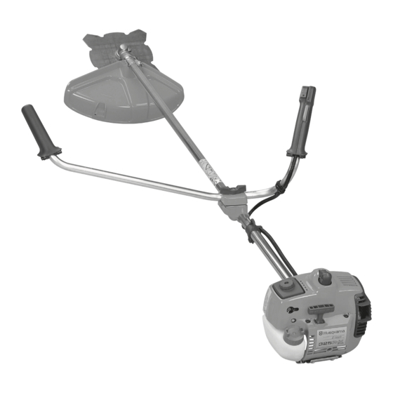
Page 16: What Is What
¥ 17. Clutch cover 18. Handlebar adjustment 19. Locking nut 20. Support flange 21. Support cup 22. Drive disc 23. Trimmer head 24. Socket spanner 25. Operator‘s Manual 26. Transport guard 27. Allen key 28. Locking pin 29. Harness 30. Spray guard 31. -
Page 17: Assembly
Assembling the handlebars (322R) • Remove the screw at the rear of the throttle handle. • Slide on the throttle handle on the right-hand side of the handlebars, (see the diagram). • Align the hole in the throttle handle for the fixing screw with the hole on the handlebars. -
Page 18: Assembly Of The Blade And Trimmer Head
Assembly of the blade and trimmer head It is extremely important that the disc drive’s/support flange’s guide engages correctly in the cutting equipment’s centre hole when assembling the cutting equipment. Cutting equipment assembled incorrectly can result in serious and/or fatal personal injury. -
Page 19: Assembling The Spray Guard And Trimmer Head
• Insert the locking pin (C) in the hole so that the axle is locked. • The trimmer head must be split to be fitted (see the diagram). Proceed as follows: • Insert your finger into the... -
Page 20: Assembling And Dismantling The Two-Part Shaft (325R-Xt)
Assembling and dismantling the two-part shaft (325R-XT) Assembling: • Make sure the handle is loose. • Guide the cut-out on the lower section of the shaft into the coupling‘s locking plate on the upper section of the shaft. The sections are then locked together. -
Page 21: Fuel Handling
• When working at continuous high revs a higher octane rating is recommended. Two-stroke oil • For the best results use HUSQVARNA two- stroke oil, which has been specially developed for clearing saws and chain saws. Mixing ratio 1:50 (2%). -
Page 22: Start And Stop
• Check that the guard is not damaged or cracked. Replace the guard if it is exposed to impact or is cracked. • Check that the trimmer head and spray guard are not damaged or cracked. Replace the trimmer head or spray guard if they are exposed to impact or are cracked. -
Page 23: Maintenance
Carburetor Your Husqvarna product has been designed and manufactured to specifications that reduce harmful emissions. After your unit has been run 8-10 tanks of fuel the engine has broken in. To ensure that your unit is at peak performance and producing the least amount of harmful... - Page 24 Final setting of the idling speed T Adjust the idling speed with the screw T, If it is necessary to readjust. First turn the idle speed adjusting screw T clockwise until the cutting attachment starts to rotate/ move. Then turn, counter- clockwise until the cutting attachment stops.
-
Page 25: Muffler
However, before using the machine you should check that the angle gear is filled to 3/4 with grease. Use HUSQVARNA special grease. Normally, the grease does not need to be changed except when the angle gear is repaired. -
Page 26: Air Filter
If the machine is used in dusty conditions the air filter should be soaked in oil, see the section on “Oiling the air filter“. Oiling the air filter Always use HUSQVARNA filter oil, order no. 503 47 73-01. The filter oil contains a solvent to make it spread evenly through the filter. -
Page 27: Sharpening The Clearing Blade
• Adjust the setting. This should be 1 mm. MAINTENANCE NOTE: Use only HUSQVARNA replacement parts. Use of other brands of replacement parts can cause damage to your unit or injury to the operator or others. Your warranty does not cover damage or liability caused by the use of accessories and/or attachments not specifically recommended by HUSQVARNA. -
Page 28: Technical Data
At max. speed, left/right handles, max: NOTE! Noise and vibration measurements are made with all the machine’s approved cutting equipment fitted. The table indicates the highest and lowest values. – English TECHNICAL DATA 322R 325R-X 1,33/21,7 1,50/24,5 1,34/34 1,26/32 1,06/27... - Page 29 Approved accessories 322R Centre hole in blades Ø 25,4 mm Threaded blade axle M10 Grass blade Saw blade Plastic knives Trimmer head Support cup Approved accessories 325R-X/R-XT Centre hole in blades Ø 25,4 mm Threaded blade axle M10 Grass blade...
-
Page 30: Emission Control Warranty Statement
REPAIR OR REPLACEMENT OF PARTS Repair or replacement of any warranted part will be perfor- med at no charge to the owner at an approved Husqvarna Forest & Garden servicing dealer. If you have any questions regarding your warranty rights and responsibilities, you should contact your nearest authorized servicing dealer or call Husqvarna Forest &... - Page 31 Super Auto II Super Auto II 1 " 4,0 m 15 cm ~2,0 m 6,5 ' 15 cm 6 " 6 " English –...
- Page 32 Tri Cut >20mm >20mm 6 Nm X 10 – English...
- Page 33 Trimmy H II 15 cm 6" 7,5 m ~ 3,7 m 15 cm 6" English –...
- Page 34 Trimmy Hit “Click” ~ 15 cm " – English 15 cm 6 " 7,0 m ~ 3,5 m 12 cm 5" “Click”...
- Page 35 Trimmy Hit Junior 15 cm 6" “Click” 15 cm 6" 5,75 m 15 cm 6" ~ 2,8 m English –...
- Page 36 Trimmy Hit Pro 15 cm 6" “Click” – English 7,5 m ~ 3,7 m 15 cm 6" 15 cm 6"...
- Page 37 Trimmy Hit VI ~ 15 cm " 15 cm " 7,0 m 12 cm 5" ~ 3,5 m “Click” English –...
- Page 38 Trimmy SII ~ 15 cm ´*31=¶53¨ – English 35-50 NM 7,0 m 12 cm 5" ~ 3,5 m "Clic"...
- Page 39 Trimmy SII ~ 15 cm ~ 15 cm 502 26 04-01 502 25 56-01 502 25 53-01 729 53 27-71 (x3) 738 21 03-04 502 26 24-01 (x2) 740 43 14-00 502 26 03-01 502 25 52-01 502 26 01-01 735 31 19-00 502 27 07-01 502 26 86-01...
- Page 40 ´*31=¶53¨ 2001W16...