Carrier AIRSTREAM 42BHE Product Data
System fan coils 600 to 4000 nominal cfm
Hide thumbs
Also See for AIRSTREAM 42BHE:
Table of Contents
Advertisement
© Carrier Corporation 2013
Product
Data
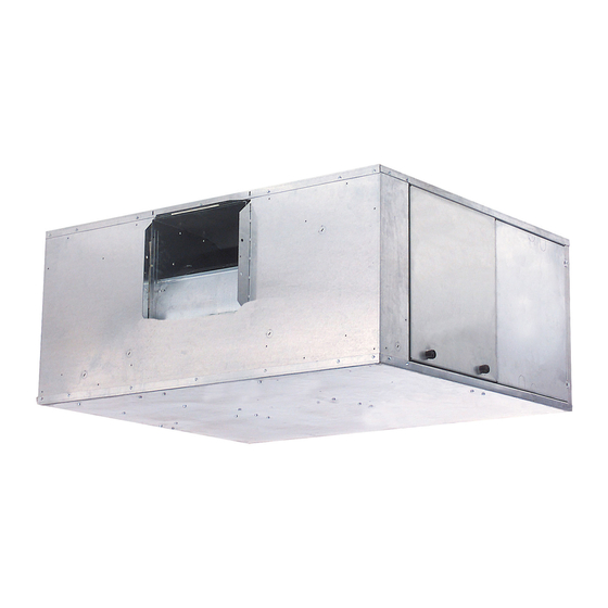
42BHE UNIT
42BVE UNIT
AIRSTREAM™
42BHE,BVE06-40
System Fan Coils
600 to 4000 Nominal cfm
Carrier's versatile belted fan coil units
satisfy design requirements:
• A selection of 8 sizes covers
nominal capacities from 600 to
4000 cfm
• Choice of motors, from
eliminates oversizing
• Wide range of coil options for 2-pipe
or 4-pipe systems
• Optional DX (direct expansion) coils
with expansion valve and distributor
• Single and three-phase electric
heat (1.0 to 39.9 kW)
Features/Benefits
The 42BHE, BVE belt drive
fan coil units provide year-
round comfort air
conditioning with central
station operating economy.
A variety of coil options
reduces first cost
Four, 6 or 8-row cooling coils combine
needed capacities with the most effi-
cient heat transfer surface. For
4-pipe systems, select from two split-
coil options. Standard coils consist of
aluminum fins securely bonded to
1
/
-in. OD seamless copper tubes.
2
Each fin's aluminum collar ensures ac-
curate control of the fin spacing, while
completely covering the tubes to
lengthen coil life. All coils also feature
manual air vents, with optional auto-
matic air vents available. Special coils
are also available with stainless steel
end sheets and bottom coil baffles. For
custom applications, special coils are
available with lower pressure drops.
1
/
to 5 hp,
4
Form 42B-6PD
Advertisement
Table of Contents

Related Manuals for Carrier AIRSTREAM 42BHE


Summary of Contents for Carrier AIRSTREAM 42BHE
-
Page 1: Features/Benefits
Product AIRSTREAM™ 42BHE,BVE06-40 Data System Fan Coils 600 to 4000 Nominal cfm Carrier’s versatile belted fan coil units satisfy design requirements: • A selection of 8 sizes covers nominal capacities from 600 to 4000 cfm • Choice of motors, from... -
Page 2: Table Of Contents
Features/Benefits (cont) Fan wheels are designed to connections for ducts is recommended. fan coil cabinets to prevent sweating provide low operating costs One-in. duct collars on discharge and and to muffle sound transmission. Pre- on return are furnished standard. These mium anti-microbial fiberglass, foil The forward-curved, centrifugal, integral duct collars cut installation time... -
Page 3: Model Number Nomenclature
R9 — Right Hand with 1 in. Closed Cell Insulation LEGEND DX — Direct Expansion HW — Hot Water a42-4365 *To be determined by Carrier sales engineer. Example: 05=0.5 in. wg †To be determined by Carrier sales engineer. Example: 07=700 actual CFM **For epoxy-coated insulation option, submit ETO (Engineer to Order) request. -
Page 4: Physical Data
Physical data UNIT SIZE 42BHE, BVE NOMINAL CFM 1000 1200 1600 2000 3000 4000 42BHE OPERATING WT (lb) 235/266 269/268 292/327 296/329 360/395 404/440 505/542 637/674 (no heat/ with heat) 42BVE OPERATING WT (lb) 232/263 234/265 283/316 287/320 337/371 412/448 504/541 606/644 (no heat/ with heat) -
Page 5: Options And Accessories
Options and accessories 42BHE, BVE OPTIONS AND ACCESSORIES Electric heat is available with the following staging options (3-phase staging is balanced). ITEM OPTION* ACCESSORY† Automatic Air Vents • 1 to 12 kW 1 stage only — single phase Controls • 3 to 12 kW 1 or 2 stage only — single phase Electric Heat •... -
Page 6: Base Unit Dimensions
Base unit dimensions 42BHE FAN COIL BASE UNIT (NO CONTROLS) WIDTH FILTER RACK WITH TOOLLESS ACCESS FROM SIDES AND BOTTOM HANGER ROD KNOCKOUT Ø5/8 TYP 4 PLCS DEPTH DETAIL 1 SCALE 0.250 SEE DETAIL 1 TOP VIEW BOTH SIDE PANELS WITH TOOLLESS CAMLOCK ACCESS 4-3/8 1-3/8... - Page 7 42BHE FAN COIL WITH MOTOR CONTROL OPTION WIDTH FILTER RACK WITH TOOLLESS ACCESS FROM SIDES AND BOTTOM HANGER ROD DEPTH KNOCKOUT Ø5/8 TYP 4 PLCS 8-11/16 DOOR DETAIL 1 OPEN SEE DETAIL 1 SCALE 0.250 MOTOR CONTROLS AND MOTOR MOUNTED SAME SIDE AS BOTH SIDE PANELS WITH COIL CONNECTIONS TOP VIEW...
-
Page 8: Base Unit Dimensions
Base unit dimensions (cont) 42BHE FAN COIL WITH ELECTRIC HEAT OPTION WIDTH FILTER RACK WITH TOOLLESS ACCESS FROM SIDES AND BOTTOM HANGER ROD DEPTH KNOCKOUT Ø5/8 TYP 4 PLCS A42-661EF SEE DETAIL 1 DETAIL 1 9-11/16 SCALE 0.250 DOOR OPEN ELECTRIC HEAT AND MOTOR MOUNTED SAME SIDE AS BOTH SIDE PANELS WITH... - Page 9 42BVE FAN COIL BASE UNIT (NO CONTROLS) 7-7/16 1" SUPPLY AIR COLLAR TOP VIEW DEPTH BOTH SIDES 4 X 4 JBOX AND MOTOR AND FRONT 2-1/16 MOUNTED SAME SIDE AS 1-7/16 PANEL WITH COIL CONNECTIONS CAMLOCK ACCESS 4-3/8 ADD 2" FOR MERV11 FILTER HEIGHT COIL RETURN CONN.
- Page 10 Base unit dimensions (cont) 42BVE FAN COIL WITH MOTOR CONTROL OPTION 1" a42-4243 MOTOR CONTROLS TOP VIEW AND MOTOR MOUNTED SAME SIDE AS DEPTH COIL CONNECTIONS 1" SUPPLY AIR COLLAR 8-3/4" 17-15/16" DOOR OPEN BOTH SIDES AND FRONT PANEL WITH CAMLOCK ACCESS 4-3/8 ADD 2"...
- Page 11 42BVE FAN COIL WITH ELECTRIC HEAT OPTION 13-13/16 1" DEPTH ELECTRIC HEAT AND MOTOR TOP VIEW MOUNTED SAME SIDE AS COIL CONNECTIONS 1" SUPPLY AIR 20" COLLAR DOOR OPEN 9-11/16" BOTH SIDES AND FRONT PANEL WITH CAMLOCK ACCESS 4-3/8 ADD 2" FOR MERV11 FILTER HEIGHT COIL RETURN CONN.
- Page 12 Base unit dimensions (cont) 42BHE UNIT CORNER WEIGHTS (lb) a42-4245 RIGHT HAND UNIT LEFT HAND UNIT CORNER WEIGHT NO ELECTRIC HEAT (lb) WITH ELECTRIC HEAT (lb) UNIT TOTAL TOTAL 42BHE WEIGHT WEIGHT NOTE: Unit weights (shown in pounds) ±10%, are based on the 8-row water filled coils, double wall cabinet construction, and 1 hp motor.
- Page 13 42BVE UNIT CORNER WEIGHTS (lb) a42-4255 LEFT HAND UNIT RIGHT HAND UNIT CORNER WEIGHT No Electric Heat (lb) With Electric Heat (lb) UNIT TOTAL TOTAL 42BVE WEIGHT WEIGHT NOTE: Unit weights (shown in pounds) ± 10%, are based on the 8-row water filled coils, double wall cabinet construction and 1 hp motor TOTAL WEIGHT UNIT CORRECTION FACTOR (lb) SINGLE WALL...
-
Page 14: Accessory Dimensions
Accessory dimensions MIXING BOX TO P VIEWS BOTTOM/REAR INLET (42BHE) TOP/REAR INLET (42BHE) TOP/FRONT INLET (42BVE) BOTTOM/FRONT INLET (42BVE) A42-667EF RIGHT HAND SIDE VIEWS DIMENSIONS (in.) 42BHE,BVE UNIT SIZE 18.5 18.5 20.25 20.25 20.25 22.75 31.0 31.0 NOTE: All dimensions in inches. - Page 15 MIXING BOX RAILS a42-4256 FRONT VIEW SIDE VIEW 1(25) 3(76) 1(25) DIMENSIONS (in.) WEIGHT (lb) DIMENSIONS (in.) WEIGHT (lb) 42BVE 42BHE Mixing Base Mixing Base UNIT UNIT Rail Box Rail Box 35.5 16.1 51.6 16.1 35.5 16.1 51.6 16.1 39.5 18.1 55.2 18.1...
- Page 16 Accessory dimensions (cont) PIPING CONNECTION LOCATION DIAGRAM* (HYDRONIC COOLING AND HEATING ONLY) RETURN AIR Drain 2(51) 1-5/8(41) A42-4246 LH Tell-Tale RH Tell-Tale HYDRONIC COIL HEAD STUB OUT SIZES (in.) 42BHE,BVE 8 Row Coil SO 6 Row Coil SO 4 Row Coil SO Heating 1 Row Heating 2 Row UNIT SIZE...
- Page 17 PIPING CONNECTION LOCATION (HYDRONIC HEATING AND COOLING) COIL ROWS DIMENSIONS (in.) 42BHE,BVE HEAT OPTIONS UNIT SIZE Cool Heat — — — — — — — — 06, 08 — — — — — — — — 10, 12 — — —...
- Page 18 Accessory dimensions (cont) PIPING CONNECTION LOCATION (DX COOLING AND HYDRONIC HEATING) a42-4257 DRAIN RETURN AIR 2 (51) 1-5/8 (41) LEGEND HWR — Hot Water Return HWS — Hot Water Supply — Liquid Line — Suction Line COIL HEADER CONNECTION SIZE (Nominal OD in Inches) 2 Row HW 1 Row HW 42 BHE,BVE UNIT SIZE...
-
Page 19: Application Data
(40 C), contact the applications engineering group. UNIT HAND Quality Carrier's belt drive fan coil units are listed by Intertek Test- ing Services (ITS). ITS's C-ETL-US listing signifies that Carrier's belt drive fan coil units have been examined by ITS and comply with the minimum requirements of U.S. -
Page 20: Selection Procedure
*Check all system component pressure ratings (coils, valves, pumps, etc.) with manufacturer and any applicable local or national piping codes prior to specifying system pressure rating. Selection procedure Refer to the Carrier Electronic Selection Program for infor- mation to determine unit sizing for your needs. -
Page 21: Performance Data
Performance data 42BHE, BVE NOMINAL COOLING CAPACITIES COOLING CAPACITY (MBtuh) HEATING CAPACITY (MBtuh) UNIT SIZE NOMINAL CFM 42BHE,BVE Total Sensible Hydronic Max Electric 17.9 - 26.8 13.8 - 18.1 13.2 - 38.3 21.9 - 33.8 17.5 - 23.3 15.9 - 47.1 1000 31.6 - 46.4 23.7 - 31.0... - Page 22 Performance data (cont) SOUND POWER DATA DISCHARGE SOUND RATINGS — A-WEIGHTED SOUND POWER LEVEL RATINGS* (dB) CENTER FREQUENCY (Hz) 42BHE,BVE UNIT SIZE NOMINAL CFM 1000 2000 4000 8000 1000 1200 1600 2000 3000 4000 *These noise ratings are calculated values, not actual test values, and apply only to the discharge of the unit, not the radiated sound levels.
- Page 23 42BHE,BVE06 FAN PERFORMANCE CURVES a42-4247 1/2 BHP 1600 RPM 1/3 BHP 1/4 BHP 1400 RPM 1/6 BHP 1/8 BHP 1200 RPM 1/12 BHP Recommended Operating Range 1000 RPM 800 RPM 600 RPM 1000 SCFM 42BHE,BVE08 FAN PERFORMANCE CURVES a42-4248 1600 RPM 3/4 BHP 1/2 BHP 1/3 BHP...
- Page 24 Performance data (cont) 42BHE,BVE10 FAN PERFORMANCE CURVES a42-4249 1600 RPM 1/2 BHP 1/3 BHP 3/4 BHP 1400 RPM 1/4 BHP 1200 RPM Recommended Operating Range 1000 RPM 800 RPM 600 RPM 1200 1400 SCFM 42BHE,BVE12 FAN PERFORMANCE CURVES 3/4 BHP 1/3 BHP 1/2 BHP a42-4250...
- Page 25 42BHE,BVE16 FAN PERFORMANCE CURVES 1 BHP a42-4251 1400 RPM 1/2 BHP 3/4 BHP 1/3 BHP 1/4 BHP 1200 RPM Recommended Operating Range 1000 RPM 800 RPM 600 RPM 1200 1600 2000 2400 SCFM 42BHE,BVE20 FAN PERFORMANCE CURVES 1-1/2 BHP 1400 RPM a42-4252 1 BHP 1200 RPM...
-
Page 26: Performance Data
Performance data (cont) 42BHE,BVE30 FAN PERFORMANCE CURVES a42-4253 1400 RPM 1-1/2 BHP 1 BHP 2 BHP 3/4 BHP 1200 RPM Recommended Operating Range 1000 RPM 800 RPM 600 RPM 1200 1600 SCFM 42BHE,BVE40 FAN PERFORMANCE CURVES 2 BHP 1200 RPM a42-4254 1000 RPM 1 BHP... -
Page 27: Typical Wiring
Typical wiring BASE UNIT, SINGLE-PHASE POWER a42-490ef.eps BASE UNIT, THREE-PHASE POWER a42-492ef... -
Page 28: Typical Control Wiring Schematics
Typical control wiring schematics a42-4088... - Page 29 a42-4089...
-
Page 30: Typical Control Wiring Schematics
Typical control wiring schematics (cont) a42-4090... - Page 31 a42-4091...
-
Page 32: Electrical Data
Electrical data 42BHE,BVE ELECTRIC HEATER DATA AVAILABILITY 42BHE,BVE ELECTRIC HEATER DATA 42BHE UNIT SIZE FULL LOAD AMPS Single-Phase Three-Phase ● ● — — — — — — 115 V 208 V 240 V 277 V 208 V 240 V 480 V ●... -
Page 33: Controls
Controls Standard control features • 8-pole control terminal strip • Auto reset temperature limit switch • 4 in. x 4 in. junction box • Manual reset backup temperature limit switch NOTE: Motor leads are wired to the 4 in. x 4 in. junction •... -
Page 34: Guide Specifications
HVAC Guide Specifications C. Fans: Size Range: 600 to 4000 Nominal Cfm Belt-driven, double-width fan wheels shall have for- Carrier Model Numbers: ward-curved blades and be statically and dynamically 42BHE (Horizontal Fan Coil Unit) balanced. Fan drive shall consist of variable-pitch... - Page 35 c. For installation in a 4-pipe system, unit shall motor contactor and terminal strip for con- be equipped with either a 4-row cooling/ nection to field-provided or factory-provided 1-row hot water heating split-circuit coil, or controller. a 4/2, 6/1, or 6/2 split-circuit coil as d.
- Page 36 Carrier Corporation • Syracuse, New York 13221 9-13 Manufacturer reserves the right to discontinue, or change at any time, specifications or designs without notice and without incurring obligations. Section 8 Pg 36 Catalog No. 04-52420015-01 Printed in U.S.A. Form 42B-6PD...