Carrier 42BJ ULTRA Series Installation Manual
Local air conditioning unit
Hide thumbs
Also See for 42BJ ULTRA Series:
- Selection manual (40 pages) ,
- Installation instructions manual (16 pages) ,
- Installation, operation and maintenance instructions (12 pages)

Related Manuals for Carrier 42BJ ULTRA Series


Summary of Contents for Carrier 42BJ ULTRA Series
- Page 1 42BJ ULTRA - Sizes 1.6-2.6-4.7 Local Air Conditioning Unit Hot/chilled water Fresh air inlet/outlet inlet Thermophonic ducting Supply/return ModuBoot ULTRA Installation manual...
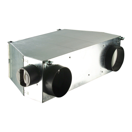
- Page 2 The photo shown on the front cover is solely for information, and not contractually binding.
-
Page 3: Table Of Contents
11.2 - Shielded electric heater with spiral fins - sizes 2.6 and 4.7 .....................24 11.3 - Replacing the electric heater ..............................24 11.4 - Wiring diagram for a single stage of the electric heater ......................25 12 - CARRIER ELECTROMECHANICAL CONTROLLER ....................26 12.1 - Description....................................26 12.2 - The various ULTRA configurations available..........................26 12.3 - Technical specification for the heating/cooling changeover switch ..................26... -
Page 4: Introduction
35BD/35SR units) supplying the room or zone where air conditioning is required. The complete system comprises one or more Carrier air or water-cooled chillers connected to one or more air handlers supplying fresh air to the 42BJ ULTRA. These may be instal-... -
Page 5: Features
2 - FEATURES The drive motor access door is coated with 13 mm of fibre wool and the air filter access panel is covered with 5 mm of The modular design of the 42BJ ULTRA allows it to be used foam. -
Page 6: Physical And Electrical Data
10 bar. Contact your local Carrier representative for advice if an application requires an operating pressure of 16 bar. Based on water entering at 6°C, room air at 25°C dry bulb, 50% relative humidity and 5 K ∆t at nominal air flow. -
Page 7: Dimensional Drawings
2.2 - Dimensional drawings 2.2.1 - Clearances for maintenance, mm Size 1.6 Removable drain pan and coil assembly Filter access side door Fan motor access door Clearance for lower filter access panel Size 2.6 Removable drain pan and coil assembly Electric heater Filter access side door Fan motor access door... - Page 8 2.2.1 - Clearances for maintenance, mm (continued) Size 4.7 Removable drain pan and coil assembly Filter access side door Fan motor access door Clearance for lower filter access panel 1100...
- Page 9 2.2 - Dimensional drawings, continued 2.2.2 - Template for fixing threaded rods, mm Size 1.6 Grommet Sizes 2.6 and 4.7 Grommet...
- Page 10 2.2 - Dimensional drawings, continued 2.2.3 - Dimensions, mm Size 1.6 Ø 16 condensate outlet Grommet Detail rep. 1 Legend: 1 Suspension lugs 2 Coil hot/chilled water 3 Electromechanical controller 4 Air filter 5 Hot/chilled water supply and return connections 6 Fresh air connection 7 Return air duct connection 8 Supply air duct connection...
- Page 11 2.2.3 - Dimensions, mm (continued) Size 4.7 1100 Ø 249 42.5 1040 Ø 8.5 Grommet Ø 8.5 Legend: 1 Suspension lugs 2 Coil hot/chilled water 3 Electromechanical controller 4 Air filter 5 Hot/chilled water supply and return connections 6 Fresh air connection 7 Return air duct connection 8 Supply air duct connection 9 Water flow control valves...
-
Page 12: Ultra Packaging
If “Export” packaging is needed, please contact your local tion site when unpacking them. Do not stack the units and do Carrier representative. not place heavy articles of any sort on them. Palletised... -
Page 13: Safety Considerations And Regulations
Europe HD 384, France NFC 15 100 and UK IEE Wiring Only specially trained and qualified technicians and installers Regulations. These devices are not supplied by Carrier. who have been fully trained on the product concerned are authorised to install, commission and service this equipment. -
Page 14: Installing The 42Bj Ultra
The method of fixing the threaded hangers (not supplied by Carrier) will depend upon the nature and condition of the cei- ling. If in doubt seek professional advice. The maximum dia- meter of the hangers is 8 mm. -
Page 15: Removing An Ultra
Every flexible pipe has a 1/2” gas screw connector. Ensure that a gasket (not supplied by Carrier) is installed be- tween the screw connector and the stop valve. i) When all units are installed, open the stop valves on the manifolds, bleed and then pressurise the circuits. -
Page 16: Fresh Air
5 - FRESH AIR NOTE: Two types of plastic spigot may be fitted to the ULTRA, depending on the capacity of the fresh air controller chosen. 5.1 - Constant flow fresh air controller One spigot can accept only the 8.3 l/s or 30 m /h controller. -
Page 17: Fan Motor
6 - FAN MOTOR 6.3 - Replacing the capacitor a) Disconnect the power supply to the ULTRA before car- 6.1 - Description rying out any work on the unit. The basic ULTRA module consists of a three-speed centrifugal b) Unscrew the 6 hexagon head screws (8 mm AF) securing fan motor, variable-speed, centrifugal fan with single wheel, the fan access panel. -
Page 18: Water Coil
(the collar is not supplied by purge valves are standard. The coil is integral with the drain Carrier). pan and coil access door to simplify removal for service. e) Remove the 4 hexagon head screws (8 mm AF) and slide Coils available are: 5 rows for two-pipe systems with change- out the coil and drain pan assembly. -
Page 19: Coil Inlet/Outlet Positions
7.3 - Coil inlet/outlet positions (dimensions in mm) 7.3.1 - ULTRA sizes 1.6 and 2.6 Two-port valves HOT WATER HOT WATER CHILLED WATER CHILLED WATER DETAIL OF COIL CONNECTOR DETAIL OF VALVE CONNECTOR 1/2” GAS CONNECTION NUT Three-port valves HOT WATER HOT WATER CHILLED WATER CHILLED WATER... - Page 20 7.3 - Coil inlet/outlet positions, continued (dimensions in mm) 7.3.2 - ULTRA size 4.7 Two-port valves 172.5 HOT WATER CHILLED DETAIL OF COIL CONNECTOR WATER OUT CHILLED Ø16 WATER IN WATER IN Ø8 DETAIL OF VALVE CONNECTOR 1/2” GAS CONNECTION NUT Three-port valves 172.5 CHILLED...
-
Page 21: Water Flow Control Valves
These valves are two-port or three-port type, with a body desi- gned to withstand a 16 bar operating pressure. 8.1 - Electrothermal actuator (on/off) This on/off type actuator is used with a Carrier room thermo- stat (electromechanical controller). BLUE NOTE:... -
Page 22: Flexible Water Hoses
- THREAD DEPTH 9.5 MM - INTERNAL THREAD 1/2” TO STANDARD NFE 03-005 • Maximum hot water temperature 90°C - PROVIDE LEAKTIGHT SEAL (NOT SUPPLIED BY CARRIER) • Operating pressure: 16 bars • Test pressure: 24 bars • Connections: 1/2” BSP threaded nut... -
Page 23: Air Filter And Access
10 - AIR FILTER AND ACCESS 10.2 - Replacing the air filter Air filters should be changed regularly. How often this is nee- 10.1 - Description ded depends on the cleanliness of the working environment and the rate at which the filter becomes clogged. The 42BJ ULTRA is fitted with a high efficiency filter. -
Page 24: Electric Heater
11 - ELECTRIC HEATER SAFETY THERMOSTAT RESET SWITCH 11.1 - Electric resistance heater type - size 1.6 • Specification: 230 V (±10%) - 1 ph - 50 Hz • Capacity per heater: size 1.6 - 1000 W +5%/-10%) • The heater is equipped with two safety devices: a) An automatically controlled integrated safety thermostat with a trigger temperature of 75°C. -
Page 25: Wiring Diagram For A Single Stage Of The Electric Heater
11.4.2 - Wiring diagram for one stage of an electric heater BRIDGE CABLE-FREE TERMINALS for a size 2.6 ULTRA SIZES 2 & 3 ELECTRIC HEATER POSITION GREEN/YELLOW BROWN 1. Remove the 2 copper connection strips 2. Wire the resistor as described BLUE Blue Brown... -
Page 26: Carrier Electromechanical Controller
The ULTRA may be fitted with an electromechanical control- This option includes a 3-port on/off valve, a heating/cooling ler developed and tested by Carrier in our research and deve- changeover switch and two insulated flexible water pipes. lopment laboratories. - Page 27 When a heating/cooling changeover switch is connected be- tween the room thermostat and the water flow control valve, the changeover between heating and cooling modes takes place automatically in accordance with the following diagram. ∆: Differential: 11,1 K ± 3,3 CM: Cooling mode HM: Heating mode θ: Water temperature in °C...
-
Page 28: Master/Slave Control
12.4 - Master/slave control It is possible to link a maximum of two ULTRAs to one Carrier thermostat without the need for additional relays. Electrothermal on/off valves rated at 230 V a.c. are used. When electric heaters are used with a cooling coil, it is essential for the electric heater to have a power relay. -
Page 29: Wiring Diagrams
12.5 - Wiring diagrams The ULTRA unit can be supplied without a control system, that is, without valves or flexible water pipes, but with fan cable bundle and electric heater ready to connect (depending on the configuration). If this option is chosen, the ULTRA is supplied without a ter- minal strip, power relay or plastic protective cover. - Page 30 12.5.4 - Five row coil, cooling Two-pipe configuration Configuration 2 tubes LIAISON: 6 x 0.75mm Cables: 6 x 0.75 mm Vitesse 1 (PV) Speed 1 (LS) Speed 2 Vitesse 2 Speed 3 (HS) Vitesse 3 (GV) Ouverture vanne froide Cooling valve open Cooling valve L : alimentation thermostat (230V a.c.)
- Page 31 12.5.4 - Six-row coil, five rows cooling, one row heating Four-pipe configuration Configuration 4 tubes Cables: 6 x 0.75 mm LIAISON: 7 x 0.75mm Vitesse 1 (PV) Speed 1 (LS) Speed 2 Vitesse 2 Speed 3 (HS) Vitesse 3 (GV) Cooling valve control Ouverture vanne froide Heating valve control...
-
Page 32: Accessories
The detector must be installed horizontally. The rubber tube must be attached to the outlet stub on the condensate drain pan by a collar (not supplied by Carrier). 4) Install the pump support bracket • The pump support bracket must be attached to the ULTRA by the two self-tapping screws provided. - Page 33 6) Connect the detector to the pump The alarm contact on the drain pump is a “Normally Open” or “Normally Closed” type, and therefore: • Connect the telephone type RJ11 connector to the pump. • Connect the 6 mm bore flexible tube to the ribbed outlet on If the condensate level is below the alarm threshold (no alarm the pump as shown in Fig.
- Page 34 Pump kit (Fig. 1) PUMP BLOCK SUPPORT BRACKET FIXING SCREWS DETECTOR BLOCK SUPPORT PUMP BLOCK SUPPORT BRACKET DETECTOR BLOCK DOUBLE SIDE ADHESIVE TAPE FLEXIBLE TUBES RUBBER TUBE LABEL SHOWING THE ATTACHMENT PLAN FOR PUMP BLOCK FIXING THE PUMP BLOCK SUPPORT BRACKET ALUMINIUM DETECTOR BLOCK BRACKET Installing the detector on the drain pan (Fig.
- Page 35 Pump connections (Fig. 3) FIXING SCREW PUMP SUPPORT BRACKET LABEL SHOWING THE ATTACHMENT PLAN Pump block installation (Fig. 4) NORMALLY OPEN COMMON PHASE NORMALLY CLOSED NEUTRAL EARTH PUMP OUTLET ELECTRICAL CONNECTION SMALL FLEXIBLE TUBE RJ11 CONNECTION (THELEPHONE TYPE) DON’T PINCH THE TUBE PUMP INLET DON’T PINCH THE TUBE CONDANSATE DRAIN...
- Page 36 Whether you live in the tropics or in Greenland Whether you suffer from the heat, from the cold or from lack of air CARRIER has the solution and can show it to you in the demonstration suite The programmes available ✔...