Table of Contents
Advertisement
Advertisement
Table of Contents

Related Manuals for Husqvarna 650CRT


Summary of Contents for Husqvarna 650CRT
- Page 1 650CRT Owner's Manual...
-
Page 2: Safety Rules
• Always refer to the operator’s guide instructions for im por tant details if the tiller is to be stored for an ex- tended period. CAUTIONS, IMPORTANTS, AND NOTES ARE A MEANS OF ATTRACTING ATTENTION TO IMPORTANT OR CRIT I CAL IN FOR MA TION IN THIS MANUAL. -
Page 3: Table Of Contents
We have com pe tent, well-trained tech ni cians and the proper tools to service or repair this unit. Please read and retain this manual. The in struc tions will enable you to assemble and main tain your tiller prop erly. Always observe the “SAFETY RULES”. SAFETY RULES ...2 CUSTOMER RESPONSIBILITIES...3... -
Page 4: Assembly
Your new tiller has been assembled at the factory with exception of those parts left unassembled for shipping purposes. To ensure safe and proper operation of your tiller all parts and hardware you assemble must be tightened securely. Use the correct tools as necessary to insure proper tightness. - Page 5 • Rotate handle assembly down. Insert rear carriage bolt fi rst, with bolt head on L.H. side of tiller and loosely assemble locknut (See Fig. 5). • Insert pivot bolt in front part of plate and tighten.
-
Page 6: Assembly
Tilt tiller forward by lifting handle. Separate cardboard cover from leveling shield. • Rotate tiller handle to the right and pull tiller out of carton. CHECK TIRE PRESSURE The tires on your unit were overinfl ated at the factory for shipping purposes. -
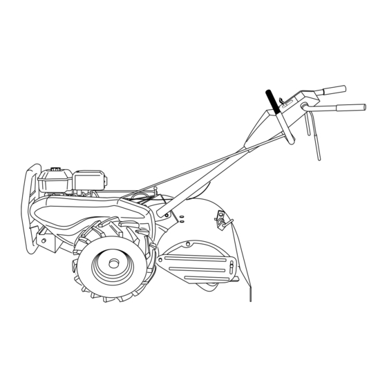
Page 7: Product View
KNOW YOUR TILLER READ THIS OWNER'S MANUAL AND SAFETY RULES BEFORE OPERATING YOUR TILLER. Compare the illustrations with your tiller to familiarize yourself with the location of various controls and adjustments. Save this manual for future reference. These symbols may appear on your Tiller or in literature supplied with the product. Learn and understand their meaning. - Page 8 The operation of any tiller can result in foreign objects thrown into the eyes, which can result in severe eye damage. Always wear safety glasses or eye shields before starting your tiller and while tilling. We recommend a wide vision safety mask for over spectacles or standard safety glasses.
- Page 9 • Release the depth stake pin. Move the depth stake down to the top hole for transporting the tiller. Place depth stake pin in hole of depth stake to lock in posi- tion. This prevents tines from scuffi ng the ground.
-
Page 10: Operation
Loose, unpacked soil helps root growth. Best tilling depth is 4" to 6" (10-15 cm). A tiller will also clear the soil of unwanted vege ta tion. The de com po si tion of this vegetable mat ter enriches the soil. -
Page 11: Maintenance Schedule
2 - Service more often when operating in dirty or dusty conditions. GENERAL RECOMMENDATIONS The warranty on this tiller does not cover items that have been subjected to operator abuse or negligence. To receive full value from the warranty, the operator must main tain tiller as instructed in this manual. -
Page 12: Maintenance
Change the oil after every 25 hours of operation or at least once a year if the tiller is not used for 25 hours in one year. Check the crankcase oil level before starting the engine and after each fi... -
Page 13: Cooling System
fl er, air fi l ter and car bu re tor are cov ered to keep wa ter out. Wa ter in en gine will short en the useful life of your tiller. •... -
Page 14: Service & Adjustments
• Maintain 20 PSI (1.4 kg/cm ) of tire pressure. If tire pres sures are not equal, tiller will pull to one side. • Keep tires free of gasoline or oil which can damage rubber. TO REMOVE WHEEL (See Fig. 21) •... -
Page 15: Service And Adjustments
SERVICE AND ADJUSTMENTS TO REPLACE GROUND DRIVE BELT (See Fig. 23) • Remove belt guard (See “TO REMOVE BELT GUARD” in this section of this manual). • Remove old belt by slipping off engine pulley fi rst then remove from transmission pulley. •... - Page 16 A badly worn tine causes your tiller to work harder and dig more shallow. Most important, worn tines cannot chop and shred organic matter as effectively nor bury it as deeply as good tines.
-
Page 17: Service & Adjustments
SERVICE AND ADJUSTMENTS ENGINE TO ADJUST THROTTLE CONTROL CABLE (See Fig. 27) The throttle control has been preset at the factory and ad just ment should not be necessary. If adjustment is necessary, proceed as follows: • With engine not running, move remote throttle control lever to “FAST”... -
Page 18: Storage
Immediately prepare your tiller for storage at the end of the season or if the unit will not be used for 30 days or more. CAUTION: Never store the tiller with gasoline in the tank inside a build ing where fumes may reach an open fl ame or spark. -
Page 19: Troubleshooting
1. Ground too dry and hard. diffi cult handling Soil balls up or clumps 1. Ground too wet. Engine runs but tiller 1. Drive control bar is not engaged. won’t move 2. V-belt not correctly adjusted. 3. V-belt is off pulley(s). -
Page 20: Repair Parts-Tiller
REPAIR PARTS TILLER - - MODEL NUMBER 650CRTC, PRODUCT NUMBER 954 32 80-30 HANDLE ASSEMBLY PART DESCRIPTION 532 18 06-34 Control, Throttle 532 00 92-66 Grip, Handle 532 15 92-28 Bar Assembly, Control 532 18 06-76 Panel, Control 871 19 10-08 Screw, Truss Hd. #10-24 UNC x 1/2... -
Page 21: Repair Parts
REPAIR PARTS TILLER - - MODEL NUMBER 650CRTC, PRODUCT NUMBER 954 32 80-30 MAINFRAME, LEFT SIDE PART DESCRIPTION 873 51 05-00 Nut, Keps 5/16-18 810 04 06-00 Washer, Lock 3/8 873 22 06-00 Nut, Hex 3/8-16 532 17 01-27 Shield, Inner Belt Guard RT... - Page 22 REPAIR PARTS TILLER - - MODEL NUMBER 650CRTC, PRODUCT NUMBER 954 32 80-30 MAINFRAME, RIGHT SIDE PART DESCRIPTION 532 16 65-32 Bumper 873 97 05-00 Locknut, Hex, Flange 5/16-18 819 11 11-16 Washer 11/32 x 11/16 x 16 Ga. 874 76 05-12 Bolt, Hex 5/16-18 x 3/4...
- Page 23 REPAIR PARTS TILLER - - MODEL NUMBER 650CRTC, PRODUCT NUMBER 954 32 80-30 TRANSMISSION PART DESCRIPTION 532 18 06-77 Transmission Assembly (In cludes Key Nos. 2-53) 532 18 06-27 Gearcase, L.H. w/Bearing (In cludes Key No. 4) 532 16 19-63 Gasket, Gearcase 532 00 50-20 Bearing, Needle 532 00 13-70 Washer, Thrust 5/8 x 1.10 x 1/32...
- Page 24 REPAIR PARTS TILLER - - MODEL NUMBER 650CRTC, PRODUCT NUMBER 954 32 80-30 TINE SHIELD PART DESCRIPTION 873 90 05-00 Nut, Lock Hex Flange 5/16-18 532 16 29-52 Shield, Side, Outer L. H. 532 00 83-93 Pin, Stake, Depth 812 00 00-35 Ring, Klip...
- Page 25 REPAIR PARTS TILLER - - MODEL NUMBER 650CRTC, PRODUCT NUMBER 954 32 80-30 TINE ASSEMBLY PART DESCRIPTION 532 00 44-59 Tine, Outer, L.H. 532 13 26-73 Clevis Pin 532 00 65-54 Tine, Inner, L.H. 532 12 46-60 Retainer, Spring Zinc 532 13 27-27 Assembly, Hub and Plate, L.H.
-
Page 26: Repair Parts-Tiller
REPAIR PARTS TILLER - - MODEL NUMBER 650CRTC, PRODUCT NUMBER 954 32 80-30 DECALS PART DESCRIPTION 532 17 70-07 Decal, Blt Grd 532 17 59-97 Decal, CNTRL PNL 532 18 08-13 Decal, Logo 532 11 06-14 Decal, Hand Placement 532 10 21-80 Decal, Shift Indicator 532 16 23-84 Decal, Warning 532 17 10-79 Decal, Engine B&S 6.5 HP... -
Page 27: Warranty Statement
It is the Owner’s and Dealer’s responsibility to make certain that the Warranty Registration Card is properly fi lled out and mailed to Husqvarna Forest & Garden Company. This card should be mailed within ten (10) days from the date of purchase in order to confi rm the warranty and to facilitate post-sale service. - Page 28 532 18 48-25 Rev. 1 05.13.03 TR Printed in U.S.A.