
Related Manuals for Husqvarna Rider Pro 18 AWD


Summary of Contents for Husqvarna Rider Pro 18 AWD
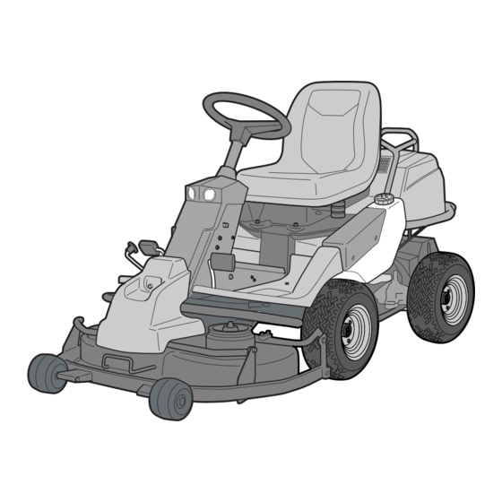
- Page 1 Operator´s manual Rider Pro 15 Pro 18 Pro 18 AWD Please read these instructions carefully and make sure English you understand them before using the machine.
-
Page 3: Table Of Contents
Rider Pro 15, Pro 18 and Pro 18 AWD Introduction ... 2 Driving and transport on public roads ... 2 Towing ... 2 Use ... 2 Serial Number ... 3 Explanation of symbols ... 4 Safety instructions ... 5 General Use ... 5 Driving on Slopes ... -
Page 4: Introduction
INTRODUCTION Congratulations Thank you for purchasing a Husqvarna Rider. Husqvarna Riders have been designed according to a unique concept with a front mounted cutting unit and patented rear wheel steering. The Rider is built to give maximum efficiency even in small and confined areas. Collected controls and a hydrostatic transmission controlled by pedals also contribute to the machine’s performance. -
Page 5: Serial Number
Proper Service Husqvarna’s products are sold all over the world and only by specialised retail traders offering complete service. This ensures that you as a customer receive only the best support and service. Before the product is delivered, the machine has, for example, been inspected and adjusted by your retailer, see the certificate in the Service Journal in this operator’s manual. -
Page 6: Explanation Of Symbols
These symbols can be found on the Rider and in the operator’s manual. Study them carefully so you understand their significance. Neutral Fast Oil level Cutting height Use hearing Hydrostatic free protection wheeling Noise emission to surroundings in accordance with the directive of the European Community. The machine’s emission is indicated in the TECHNI- CAL DATA chapter and on the decal. -
Page 7: Safety Instructions
SAFETY INSTRUCTIONS Safety Instructions These instructions are for your safety. Read them carefully. WARNING! The inserted symbol means that important safety instructions need to be observed. It applies to your safety. General Use • Read all the instructions in this operator’s manual and on the machine before you start it. - Page 8 SAFETY INSTRUCTIONS • Take care when rounding a fixed object, so that the blades do not hit it. Never run the machine over foreign objects. • Only use the machine in daylight or in other well- lit conditions. Keep the machine at a safe distance from holes or other irregularities in the ground.
-
Page 9: Driving On Slopes
SAFETY INSTRUCTIONS Driving on Slopes Driving on slopes is one of the operations where the risk of the driver losing control of the machine or of it overturning is the greatest; this can result in serious injury or death. All slopes demand extra care. -
Page 10: Children
SAFETY INSTRUCTIONS Children • Serious accidents may occur if you fail to be on your guard for children in the vicinity of the machine. Children are often attracted to the machine and mowing. Never assume that children will stay put where you last saw them. •... - Page 11 SAFETY INSTRUCTIONS IMPORTANT INFORMATION Avoid sparking and its consequences by: Wearing protective glasses. Make sure that the fuel cap is fitted and that no flammable liquids are stored in an open container. Do not work on the starter motor circuit in the vicinity of spilt fuel.
-
Page 12: Transport
SAFETY INSTRUCTIONS • Do not change the setting of governors and avoid running the engine at excessively high revs. If you run too fast, you risk damaging the machine components. • Observe the risk of injury caused by moving or hot parts if the engine is started with the engine cover open or protective cowlings removed. -
Page 13: Presentation
Presentation Congratulations on your choice of an exceptionally high quality product. This operator’s manual describes Rider Pro 15, Pro 18 and Pro 18 AWD. The machines are equipped with a four-stroke V- Twin engine from Kawasaki. The figures denote the amount of horse power. -
Page 14: Cutting Unit
Cutting Unit The machines can be equipped with numerous attachments. The BioClip unit finely chops the grass several times before returning it to the lawn as fertiliser. The Combi unit functions as a BioClip unit when a BioClip plug is fitted, but can be reset to rear ejection by removing the BioClip plug. -
Page 15: Throttle Control
Throttle Control The throttle is used to control the speed of the engine and thereby also the rotation speed of the blades. In order to increase or decrease the engine speed, the control is moved forwards or backwards respectively. Avoid idling the engine for long periods, as there is a risk of carbon build-up on the spark plugs. -
Page 16: Lifting Lever For The Cutting Unit
Lifting Lever for the Cutting Unit The lifting lever is used to put the cutting unit in either the transport or mowing positions. 1. Pull the lever backwards to the locked position to engage the transport position. The unit is raised and the blades stop rotating. 2. -
Page 17: Parking Brake
Parking Brake The parking brake is activated as follows: 1. Press down the parking brake pedal (1). 2. Press the lock button on the steering column (2) in fully. 3. Release the parking brake pedal while keeping the button pressed in. The parking brake lock is automatically disengaged when the brake pedal is pressed down. -
Page 18: Driving
WARNING! Do not use the Rider on ground that slopes more than 15°. Mow upwards and downwards on slopes, never sideways. Avoid sudden directional changes. Mowing Tips • Find and mark out any stones and other fixed objects to avoid colliding with them. •... -
Page 19: Clutch Control
Rider to be moved when the engine is shut off. The figure shows the clutch control pulled out. Pro 18 AWD has one control for the front axle and one control for the rear axle. Pull the controls to their end positions. Do not use an intermediate position. -
Page 20: Before Starting
Before Starting IMPORTANT INFORMATION The air intake grille in the engine cover behind the driver’s seat must not be blocked by, for example, clothing, leaves, grass or dirt. Impaired cooling of the engine. Risk of major engine damage. • Read the safety instructions and the presentation of the Rider before starting. - Page 21 4. If the engine is cold, the choke control shall be moved backwards to its end position. 5. Turn the ignition key to the start position. 6. When the engine starts, immediately release the ignition key so that it returns to the neutral position.
-
Page 22: Driving The Rider
Driving the Rider 1. Release the parking brake by first pressing down the parking brake pedal and then releasing the brake pedal. 2. Carefully press down one of the pedals until the required speed is attained. Pedal (1) is pressed down to travel forwards and pedal (2) to reverse. -
Page 23: Stopping The Engine
Stopping the Engine If the engine has been worked hard, it is preferable to let the engine idle for a minute so it is running at its normal working temperature when it is stopped. Avoid idling the engine for long periods, as there is a risk of carbon build-up on the spark plugs. -
Page 24: Maintenance
Maintenance Schedule The following is a list of maintenance procedures that must be performed on the rider. For points marked with footnote number 4, turn to an authorised service representative. = Described in this operator’s manual. Maintenance Check for fuel and oil leaks Check the parking brake Check the engine’s oil level (every refuelling) Check the fuel pump’s air filter... - Page 25 Maintenance and replacement are required more often in dusty conditions. use, the Rider should be lubricated twice weekly. Pro 18 only. Pro 18 AWD only. Replace first after 50 hours. = Described in this operator’s manual. = Not described in this manual.
-
Page 26: Dismantling The Rider Covers
Dismantling the Rider Covers The engine becomes accessible for service when the engine cover is opened. Engine Cover 1. Pull the seat forward to its foremost position. 2. Fold up the seat. 3. Turn the cover lock on the top of the engine cover anti-clockwise a 1/4 turn. -
Page 27: Checking And Adjusting The Steering Cables
Left-hand Wing Cover Loosen the screws (2) and lift off the cover. Checking and Adjusting the Steering Cables The steering is governed by means of cables. After a period of use these can become stretched, which means the steering setting may have changed. -
Page 28: Adjusting The Parking Brake
6. Replace the spring (A). 7. Check that the parking brake works. Adjusting the Parking Brake Pro 18 AWD Check that the parking brake is adjusted correctly by placing the machine on a slope with the front and rear axles disengaged. Apply and lock the parking brake. -
Page 29: Checking And Adjusting The Throttle Cable
Checking and Adjusting the Throttle Cable Check that the engine responds to throttle increases and that a good engine speed is attained at full throttle. If doubts arise, contact your service representative. If adjustments are necessary, they can be made as follows for the lower cable: 1. -
Page 30: Replacing The Fuel Filter
Replacing the Fuel Filter Replace the fuel filter mounted on the supply line after every 100 hours (once per season) or more frequently if it is clogged. Replace the filter as follows: 1. Open the engine cover. 2. Move the hose clamps away from the filter. Use a pair of flat pliers. -
Page 31: Replacing The Air Filter Pro 15
Replacing the Air Filter Pro 15 If the engine seems weak or runs unevenly, the air filter may be clogged. If run with a soiled air filter, carbon can build-up on the spark plugs and lead to malfunction. Consequently, it is important to periodically replace the air filter (see ”Maintenance \ Maintenance Schedule”... -
Page 32: Replacing The Air Filter Pro 18
Replacing the Air Filter Pro 18 If the engine seems weak or runs unevenly, the air filter may be clogged. If run with a soiled air filter, carbon can build-up on the spark plugs and lead to malfunction. Consequently, it is important to periodically replace the air filter (see ”Maintenance \ Maintenance Schedule”... -
Page 33: Checking The Engine's Cooling Air Intake
Checking the Engine’s Cooling Air Intake Clean the air intake grille in the engine cover behind the driver’s seat. Open the engine cover. WARNING! The cooling air intake rotates when the engine is running. Watch your fingers. Check that the engine cooling air intake is free of leaves, grass, and dirt. -
Page 34: Checking The Battery Acid Level
Checking the Acid Level in the Battery Check that the acid level in the battery lies between the markings. When refilling, only distilled water may be used to fill the cells. WARNING! Actions with acid contact External: Rinse thoroughly with water. Internal: Drink large quantities of water or milk. -
Page 35: Checking The Safety System
Checking the Safety System The Rider is equipped with a safety system that prevents starting or driving under the following conditions. The engine should only be possible to start when the cutting unit is in its raised position and the parking brake is applied. -
Page 36: Replacing The Light Bulbs
Replacing the Light Bulbs For information about the bulb type, see ”Technical Data”. Unscrew the two screws holding the cover on the power steering housing. Lift up the cover and turn it around the steering shaft. Unscrew the two screws holding the lamp insert. -
Page 37: Fuses
Fuses The main fuse is placed in a detachable holder under the battery case’s cover, in front of the battery. Type: Flat pin, 15 A. The fuse for the power outlet is placed under the ignition switch, behind the side plate on the control panel. -
Page 38: Replacing The Rear Drive Belt
Replacing the Rear Drive Belt Pro 15 and Pro 18: Removal 1. Remove the transmission cover. 2. Unhook the spring on the belt tensioner (A). 3. Remove the hose clip on the middle and the belt guide for the centre belt. 4. - Page 39 7. Pull the pump belt off of the engine’s pulley and move it under the engine belt pulleys. 8. Pull out the pump belt through the opening under the pivot bearing and past the belt tensioner’s disc. Assembly 1. Pull the pump belt through the opening under the pivot bearing and on the outside past the belt tensioner’s disc.
-
Page 40: Replacing The Hydraulic Pump's Drive Belt Pro 18 Awd
Replacing the Hydraulic Pump’s Drive Belt Pro 18 AWD Removal 1. Remove the transmission cover. 2. Unhook the spring on the belt tensioner. 3. Remove the belt guide for the centre belt. 4. Pull off the centre belt from the engine’s pulley and pull out the rear section. - Page 41 6. Remove the clamp on the hydraulic pipes, located under the fan. Loosen the pipe connections from the pump slightly, bend the hydraulic pipes down and pull the cooling fan out backwards. 7. Pull the belt off of the pump’s pulley. 8.
-
Page 42: Replacing The Centre Belt
17. Fit the belt guide for the centre belt. 18. Hook the spring on the belt tensioner. Replacing the Centre Belt 1. Remove the hose clip in the middle (Pro 15, Pro 18) and the rear belt guide for the centre belt (all machines). -
Page 43: Replacing The Front Belt Pro 15, Pro 18
3. Position the belt on the support pulley and tighten the belt guide. 4. Fit the cutting equipment. Replacing the Front Belt Pro 18 AWD Dismantling The entire belt is removed according to the following when a snow blade is to be attached to the machine. - Page 44 2. Fit the centre belt in position on the centre pulley. 3. Reset the cutting unit in the mowing position. Make sure that the tongue (3) mates with the loop on the underside of the machine. 4. The belt is fitted on the cutting unit’s drive pulley once the unit has been pushed back into its rear position.
-
Page 45: Fitting The Cutting Unit
Fitting the Cutting Unit WARNING! Wear protective glasses when assembling the cutting unit. The spring that tensions the belt can fly off and cause personal injury. 1. Place the Rider on a flat surface and apply the parking brake. Check that the lever for setting the cutting height is in the lowest position. -
Page 46: Removing The Cutting Unit
7. Fit the anti-scalp rollers in position 8. Fit the front cover. 9. Secure the springs on the adjuster pulley. There are two designs, see the figures. Removing the Cutting Unit WARNING! Wear protective glasses when dismantling the cutting unit. The springs that tension the belt can fly off and cause personal injury. -
Page 47: Checking And Adjusting The Cutting Unit's Ground Pressure
Checking and Adjusting the Cutting Unit’s Ground Pressure In order to achieve the best mowing result the cutting unit should follow the ground without touching it too heavily. The pressure is adjusted using a screw on each side of the Rider. 1. -
Page 48: Checking The Parallelism Of The Cutting Unit
Checking the Parallelism of the Cutting Unit Check the cutting unit’s parallelism as follows: 1. Check the air pressure in the tyres 60 kPa / 0.6 bar / 9 PSI. 2. Place the Rider on a flat surface. 3. Put the lifting lever in the mowing position. 4. -
Page 49: Replacing The Cutting Unit's Belts
Changing the Belt on the Combi 94 and Combi 112 WARNING! Protect your hands with gloves when working with the blades. On cutting units with ”collision-proof” blades, the blades are driven by a V-belt. Do as follows to replace the V-belt: 1. -
Page 50: The Cutting Unit's Service Position
The Cutting Unit’s Service Position In order to provide good accessibility for cleaning, repair and servicing, the unit can be set in the service position. The service position means that the unit is raised and locked in the vertical position. Placing in the Service Position 1. - Page 51 4. Fit the two anti-scalp rollers on each side of the cutting unit’s rear section. WARNING! Wear protective glasses when dismantling the cutting unit. The springs that tension the belt can fly off and cause personal injury. 5. Loosen the spring on the drive belt’s belt idler. There are two designs, see the figures.
- Page 52 WARNING! Observe caution to avoid trapping your hand. 8. Lift off the drive belt (1). Now pull out the split pin (2). 9. Pull the frame forwards and refit the pin. 10. Grasp the cutting unit’s front edge, pull out and lift up into the service position.
-
Page 53: Inspecting The Blades
Inspecting the Blades It is important that the blades are undamaged and well-ground to give the best mowing result. Check that the blades’ mounting bolts are tightened. IMPORTANT INFORMATION Replacement or sharpening of the blades should be carried out by an authorised service representative. -
Page 54: Removing The Bioclip Plug (Combi)
Removing the BioClip Plug (Combi) To change a Combi unit from the BioClip function to a cutting unit with rear ejection, remove the BioClip plug, which is located under the unit, attached with three screws. 1. Put the unit in the service position, see ”Placing in the Service Position”. -
Page 55: Lubrication
LUBRICATION Lubrication Chart Pro 15 8009-589 The position numbers for the lubrication points refer to the lubrication instructions on the following pages. English –... -
Page 56: Lubrication Chart Pro 18
LUBRICATION Lubrication Chart Pro 18 8009-504 The position numbers for the lubrication points refer to the lubrication instructions on the following pages. – English... -
Page 57: Lubrication Chart Pro 18 Awd
LUBRICATION Lubrication Chart Pro 18 AWD 8009-681 The position numbers for the lubrication points refer to the lubrication instructions on the following pages. English –... -
Page 58: General
General Remove the ignition key to prevent unintentional movements during lubrication. When lubricating with an oilcan, it ought to be filled with engine oil. When lubricating with grease, unless otherwise stated, grease 503 98 96-01 or another chassis or ball bearing grease offering good corrosion protection shall be used. -
Page 59: Pedal Mechanism In Frame Tunnel
2. Pedal Mechanism in Frame Tunnel Lubricate the pedal mechanism in the frame tunnel. Remove the cover of the frame tunnel by loosening the screws (two on the steering servo housing). Work the pedals and lubricate the moving parts with an oilcan. - Page 60 4. Three-Point Link and Joints Lubricate the three-point link and joints for cutting height setting stay behind the right, front wheel. Lubricate using an oilcan. 5. Driver’s Seat Tilt the seat back. Lubricate the lengthways adjustment mechanism with the oilcan. Lubricate the lengthways adjustment runners with the oilcan.
- Page 61 7. Belt Tensioner Lubricate using a grease gun, 1 nipple from the right-hand side under the engine’s lower belt pulley, until grease is forced out. Use only good quality molybdenum disulphide grease. Grease from well-known brand names (petrochemical companies, etc.) usually maintains a good quality.
- Page 62 Changing the Engine Oil The engine oil should be changed the first time after 8 hours running time. It should then be changed after every 100 hours of running time. When operating with a heavy load or at high ambient temperatures, replace every 50 hours. WARNING! Engine oil can be very hot if it is drained directly after stopping...
- Page 63 Filter replacement on Pro 18 is done at the same time as changing the oil. 12. Hydraulic System and Transmission Oil level Pro 18 AWD 1. Remove the transmission cover. 2. Check the level, it should be visible in the sight glass at 20 °C when the machine stands flat.
- Page 64 Avoid skin contact; wash with soap and water in case of spills. 14. Hydraulic Fluid Filter, Replacing Pro 18, Pro 18 AWD 1. Remove the oil filter. If necessary, use a filter remover. 2. Wipe new, clean engine oil onto the seal for the new filter.
- Page 65 15. Parking Brake Cable Pro 18 AWD Remove the cover over the frame tunnel. Lubricate both ends of the cable. Remove the cable’s rubber casing when lubricating. Lubricate the cable with an oilcan, press the brake pedal a few times and lubricate again.
-
Page 66: Trouble Shooting Chart
TROUBLE SHOOTING GUIDE Problem The engine will not start Starter does not turn the engine The engine runs erratically The engine lacks power Engine overheating Battery does not charge The Rider vibrates Uneven mowing results – English Cause • No fuel in the fuel tank •... -
Page 67: Storage
When ordering spare parts, please specify the Rider’s year of purchase, model, type, and serial number. Always use genuine Husqvarna spare parts. An annual check-up or trimming at an authorised service representative is a good way to ensure that your Rider performs at its best the following season. -
Page 68: Wiring Diagram
Rider Pro 15 -18 Rider Pro 18 AWD Microswitch, hydrostatic transmission Microswitch, cutting unit Microswitch, seat Ignition key Chronometer Start relay Engine Main fuse 15 A Fuse 7.5 A 10. Switch for the power outlet 11. Power outlet 12. Switch for the lights 13. - Page 69 WIRING DIAGRAM 8009-588 Rider Pro 15 -18 English –...
- Page 70 WIRING DIAGRAM Rider Pro 18 AWD 8009-679 – English...
-
Page 71: Technical Data
12V, 20W., 44860 WFL 38° Tuff Torq K 66M Tuff Torq K 66M SAE 10W/30, class SF-CC 7 positions Rider Pro 18 AWD 2,030 mm / 6.65 ft 900 mm / 2.95 ft 1,130 mm / 3.70 ft 284 kg / 626 lb 873 mm / 2.86 ft... - Page 72 Cutting unit Combi 94 Mowing width 940 mm / 3.08 ft Cutting heights 30 - 90 mm / 1 3/16"–3 1/2" Cutting height setting 40 mm / 1 9/16" Blade diameter 360 mm / 14" Weight 52 kg / 115 lb When this product is spent and is no longer used it should be returned to the dealer or other authority for recycling.
-
Page 73: Eu Declaration Of Conformity
Husqvarna AB, SE-561 82 Huskvarna, Sweden, tel: +46-36-146500, declares under sole responsibility that Rider Husqvarna Rider Pro 15, Pro 18 and Pro 18 AWD dating from 2005 serial numbers and onwards (the year is clearly stated on the rating plate, followed by the serial number), complies with the requirements of the COUNCIL’S DIRECTIVE: - of June 22, 1998 ”relating to machinery”... -
Page 74: Service Journal
Action Delivery Service 1. Fill the battery with battery acid and charge for four hours. 2. Fit the steering wheel, seat and, where applicable, other components. 3. Attach the cutting unit. 4. Adjust the cutting unit: Adjust the lifting springs (the ”weight” of the cutting unit should be 12-15 kg, if a brush is to be used, set to maximum spring power). -
Page 75: Hour Service
Action 25-Hour Service 1. Clean the air filter’s pre-cleaner (foam plastic filter). (Shorter intervals for dusty operating conditions.) 2. Clean the engine’s cooling air intake and the transmission’s air intake. 3. Clean the fuel pump’s air filter. (in dusty operating conditions). 4. - Page 76 Action 50-Hour Service 1. Clean/Replace the air filter’s pre-cleaner (foam plastic filter). (Shorter intervals for dusty operating conditions.) 2. Clean the engine’s cooling air intake and the transmission’s air intake. 3. Clean the air cleaner’s paper filter. 4. Clean the fuel pump’s air filter. 5.
- Page 77 Action 100/200-Hour Service 1. Change engine oil. Replace the oil filter every 200 hours. 2. Clean/Replace the air filter’s pre-cleaner (foam plastic filter). 3. Clean the air cleaner’s paper filter. Replace every 200 hours. (Shorter intervals for dusty operating conditions.) 4.
- Page 78 Action 300-Hour Service 1. Inspect the machine. Additional work? 2. Change engine oil. Replace the oil filter every 200 hours. 3. Replace the air filter (foam plastic filter). 4. Replace the air filter (paper filter). 5. Clean the engine’s cooling air intake and the transmission’s air intake.
- Page 79 Action At Least Once Each Season 1. Change the engine oil (100 hours). 2. Clean/Replace the air filter’s pre-cleaner (foam plastic filter) (25 hours). (Shorter intervals for dusty operating conditions.) 3. Clean/Replace the air filter’s paper filter (100 hours). (Shorter intervals for dusty operating conditions.) 4.
- Page 80 SERVICE JOURNAL Date, mileage reading, stamp, Action signature – English...
- Page 81 SERVICE JOURNAL Date, mileage reading, stamp, Action signature English –...
- Page 82 SERVICE JOURNAL Date, mileage reading, stamp, Action signature – English ´®z+RÆh¶6j¨...
- Page 83 English –...
- Page 84 115 00 07-26 ´®z+RÆh¶6j¨ 2005W05...