Table of Contents
Advertisement
Advertisement
Table of Contents

Related Manuals for Husqvarna LTH140


Summary of Contents for Husqvarna LTH140
- Page 1 LT H 1 4 0 Owner’s Manual...
-
Page 2: Safety Rules
Safe Operation Practices for Ride-On Mowers IMPORTANT: THIS CUTTING MACHINE IS CAPABLE OF AMPUTATING HANDS AND FEET AND THROWING OBJECTS. FAILURE TO OBSERVE THE FOLLOWING SAFETY INSTRUCTIONS COULD RESULT IN SERIOUS INJURY OR DEATH. GENERAL OPERATION • Read, understand, and follow all instructions in the manual and on the machine before starting. -
Page 3: Product Specifications
Please read and retain this manual. The instructions will enable you to assemble and maintain your tractor prop- erly. Always observe the "SAFETY RULES". MODEL NUMBER LTH140 SERIAL NUMBER ____________________________________ DATE OF PURCHASE __________________________ THE MODEL AND SERIAL NUMBERS WILL BE FOUND ON A PLATE UNDER THE SEAT. -
Page 4: Table Of Contents
TABLE OF CONTENTS SAFETY RULES ... 2 PRODUCT SPECIFICATIONS ... 3 CUSTOMER RESPONSIBILITIES ... 3, 14-18 ASSEMBLY ... 7-9 OPERATION ... 10-13 MAINTENANCE SCHEDULE ... 14 INDEX Adjustments: Brake ... 21 Carburetor ... 24 Clutch ... 21 Mower: Front-To-Back ... 20 Side-To-Side ... -
Page 5: Contents Of Hardware Pack
CONTENTS OF HARDWARE PACK Parts Bag contents shown full size (1) Knob (1) Shoulder Bolt 5/16-18 (1) Washer 17/32 x 1-3/16 x 12 Gauge (4) Washers 13/32 x 13/16 x 16 Ga. (2) Carriage Bolts 3/8-16 x 1-1/4 (4) Crownlock Nuts 3/8-16 (2) Screws #10 x 5/8 (2) Lock Washer s #10 (2) Weld Nuts #10... -
Page 6: Tools Required For Assembly
Your new tractor has been assembled at the factory with exception of those parts left unassembled for shipping purposes. To ensure safe and proper operation of your tractor, all parts and hardware you assemble must be tightened securely. Use the correct tools as necessary to insure proper tightness. TOOLS REQUIRED FOR ASSEMBLY A socket wrench set will make assembly easier. -
Page 7: How To Set Up Your Tractor
HOW TO SET UP YOUR TRACTOR PREPARE BATTERY (See Fig. 2) CAUTION: Wear eye and face shield. Wash hands or clothing immediately if accidentally in contact with battery acid. Do not smoke. Fumes from charged battery acid are explosive. Read the instructions included with the battery vent caps. - Page 8 INSTALL BATTERY (See Figs. 4 and 5) CAUTION: Do not short battery termi- nals. Before installing battery, remove metal bracelets, wristwatch bands, rings, etc. Positive terminal must be connected first to prevent sparking from acciden- tal grounding. • Lift seat to raised position. •...
- Page 9 ASSEMBLE GAUGE WHEELS TO MOWER DECK (See Fig. 7) Assemble gauge wheels with tractor on a flat level surface. • Adjust mower to desired cutting height (See “TO AD- JUST MOWER CUTTING HEIGHT” in the Operation section of this manual). •...
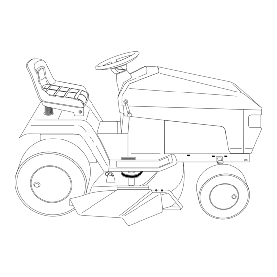
- Page 10 KNOW YOUR TRACTOR READ THIS OWNER'S MANUAL AND SAFETY RULES BEFORE OPERATING YOUR TRACTOR Compare the illustrations with your tractor to familiarize yourself with the locations of various controls and adjustments. Save this manual for future reference. ATTACHMENT CLUTCH SWITCH LIGHT SWITCH CLUTCH/BRAKE PEDAL...
-
Page 11: How To Use Your Tractor
The operation of any tractor can result in foreign objects thrown into the eyes, which can result in severe eye damage. Always wear safety glasses or eye shields while operating your tractor or performing any adjustments or repairs. We recom- mend wide vision safety mask for over the spectacles or standard safety glasses. -
Page 12: Before Starting The Engine
TO OPERATE MOWER (See Fig. 11) Your tractor is equipped with an operator presence sensing switch. Any attempt by the operator to leave the seat with the engine running and the mower clutch engaged will shut off the engine. • Select desired height of cut. -
Page 13: Mowing Tips
CAUTION: Fill to bottom of gas tank filler neck. Do not overfill. Wipe off any spilled oil or fuel. Do not store, spill or use gasoline near an open flame. TO START ENGINE (See Fig. 10) When starting engine for the first time or if engine has run out of fuel, it will take extra cranking time to move fuel from the tank to the engine. -
Page 14: Maintenance Schedule
CUSTOMER RESPONSIBILITIES MAINTENANCE SCHEDULE FILL IN DATES AS YOU COMPLETE REGULAR SERVICE Check Brake Operation Check Tire Pressure Check for Loose Fasteners Sharpen/Replace Mower Blades Lubrication Chart Check Battery Level/Recharge Clean Battery and Terminals Check Transaxle Cooling Adjust Blade Belt(s) Tension Adjust Motion Drive Belt(s) Tension Check Engine Oil Level Change Engine Oil... -
Page 15: Customer Responsibilities
CUSTOMER RESPONSIBILITIES TRACTOR Always observe safety rules when performing any mainte- nance. BRAKE OPERATION If tractor requires more than six (6) feet stopping distance at high speed in highest gear, then brake must be adjusted. (See "TO ADJUST BRAKE" in the Service and Adjust- ments section of this manual). - Page 16 CUSTOMER RESPONSIBILITIES BATTERY (See Fig. 16) Your tractor has a battery charging system which is suffi- cient for normal use. However, periodic charging of the battery with an automotive charger will extend it's life. • Acid solution level in each battery cell should be even with bottoms of vent wells.
- Page 17 CUSTOMER RESPONSIBILITIES ENGINE LUBRICATION Only use high quality detergent oil rated with API service classification SF or SG. Select the oil's SAE viscosity grade according to your expected operating temperature. SAE VISCOSITY GRADES 5W-30 ° -20° 0° 30° 32° 40° °...
-
Page 18: Carburetor
CUSTOMER RESPONSIBILITIES CLEAN AIR INTAKE/COOLING AREAS To insure proper cooling, make sure the grass screen, cooling fins, and other external surfaces of the engine are kept clean at all times. Every 100 hours of operation (more often under extremely dusty, dirty conditions), remove the blower housing and other cooling shrouds. -
Page 19: Clutch
SERVICE AND ADJUSTMENTS CAUTION: BEFORE PERFORMING ANY SERVICE OR ADJUSTMENTS: • Depress clutch/brake pedal fully and set parking brake. • Place motion control lever in neutral (N) position. • Place attachment clutch in "DISENGAGED" position. • Turn ignition key "OFF" and remove key. •... -
Page 20: Side-To-Side
SERVICE AND ADJUSTMENTS TO LEVEL MOWER HOUSING Adjust the mower while tractor is parked on level ground or driveway. Make sure tires are properly inflated (See “PRODUCT SPECIFICATIONS” on page 3 of this manual). If tires are over or underinflated, you will not properly adjust your mower. -
Page 21: Service And Adjustments
SERVICE AND ADJUSTMENTS TO REPLACE MOWER BLADE DRIVE BELT (See Fig. 25) The mower blade drive belt may be replaced without tools. Park the tractor on level surface. Engage parking brake. BELT REMOVAL - • Remove mower from tractor (See “TO REMOVE MOWER”... - Page 22 SERVICE AND ADJUSTMENTS TO REPLACE MOTION DRIVE BELT (See Fig. 28) Park the tractor on level surface. Engage parking brake. For assistance, there is a belt installation guide decal on bottom side of left footrest. • Remove mower (See “TO REMOVE MOWER” in this section of this manual.) •...
- Page 23 SERVICE AND ADJUSTMENTS TO ADJUST STEERING WHEEL ALIGNMENT If steering wheel crossbars are not horizontal (left to right) when wheels are positioned straight forward, remove steer- ing wheel and reassemble per instructions in the Assembly section of this manual. FRONT WHEEL TOE-IN/CAMBER The front wheel toe-in and camber are not adjustable on your tractor.
-
Page 24: Throttle Control Cable
SERVICE AND ADJUSTMENTS TO REPLACE FUSE Replace with 30 amp automotive-type plug-in fuse. The fuse holder is located in the engine compartment, directly in front of the dash. TO REPLACE HEADLIGHT BULB • Raise hood. • Pull bulb holder out of the hole in the backside of the grill. - Page 25 SERVICE AND ADJUSTMENTS TO ADJUST CARBURETOR (See Fig. 34) The carburetor has been preset at the factory and adjust- ment should not be necessary. However, minor adjust- ment may be required to compensate for differences in fuel, temperature, altitude or load. If the carburetor does need adjustment, proceed as follows: In general, turning the adjusting needles in (clockwise) decreases the supply of fuel to the engine giving a leaner...
-
Page 26: Cleaning
Immediately prepare your tractor for storage at the end of the season or if the tractor will not be used for 30 days or more. CAUTION: Never store the tractor with gasoline in the tank inside a building where fumes may reach an open flame or spark. -
Page 27: Troubleshooting Points
TROUBLESHOOTING POINTS PROBLEM CAUSE Will not start Out of fuel. Engine not “CHOKED” properly. Engine flooded. Bad spark plug. Dirty air filter. Dirty fuel filter. Water in fuel. Loose or damaged wiring. Carburetor out of adjustment. Engine valves out of adjustment. Hard to start Dirty air filter. - Page 28 TROUBLESHOOTING POINTS PROBLEM CAUSE Engine continues to run Faulty operator-safety presence control system. when operator leaves seat with attachment clutch engaged Poor cut - uneven Worn, bent or loose blade. Mower deck not level. Buildup of grass, leaves, and trash under mower. Bent blade mandrel.
- Page 29 14 HP 42" TRACTOR - MODEL NO. LTH140 (954001192A) 01613 - (WH#140421) SCHEMATIC AMMETER WHITE BLACK IGNITION SWITCH BLACK BLUE IGNITION SWITCH POSITION CIRCUIT M + G B + L START B + S + L BATTERY FUSE 30 AMP.
-
Page 30: Repair Parts
REPAIR PARTS 14 HP 42" TRACTOR - MODEL NO. 954001192A ELECTRICAL BATTERY BOX WITH LID D .C Comm. Harn. 140421 140426... - Page 31 REPAIR PARTS 14 HP 42" TRACTOR - MODEL NO. 954001192A ELECTRICAL PART DESCRIPTION 532121537 Battery 12 Volt 30 Amp 874760412 Bolt Hex Hd 1/4-20unc X 3/4 819091016 Washer 9/32 X 5/8 X 16 Ga 810040400 Washer Lock Hvy Helical 1/4 532121264 Caps Battery 20/25/30 Amp 873220400...
-
Page 32: Chassis And Enclosures
REPAIR PARTS 14 HP 42" TRACTOR - MODEL NO.954001192A CHASSIS AND ENCLOSURES... - Page 33 REPAIR PARTS 14 HP 42" TRACTOR - MODEL NO. 954001192A CHASSIS AND ENCLOSURES KEY PART NO. NO. DESCRIPTION 532140341 Chassis 11 ga 532140356 Drawbar 817490612 Screw, Thd., Roll. 3/8-16 x 3/4 532125453 Saddle 532126471 Clip Insulator .406 Mtg. Hole 532140452 Dashboard 872140608 Bolt, Carriage 3/8-16 UNC x 1...
- Page 34 REPAIR PARTS 14 HP 42" TRACTOR - MODEL NO. LTH140 (954001192A) DRIVE...
- Page 35 REPAIR PARTS 14 HP 42" TRACTOR - MODEL NO. LTH140 (954001192A) DRIVE PART DESCRIPTION 532144436 Transaxle Assembly 532142431 Spring, Return, Brake 532143995 Pulley, Transaxle 532141003 Rod Shift Hydro LT 532137140 Clutch Elect 105 Ft/Lb 876020416 Pin Cotter 1/8 x 1 CAD...
- Page 36 REPAIR PARTS 14 HP 42" TRACTOR - MODEL NO. LTH140 (954001192A) ENGINE OPTIONAL EQUIPMENT Spark Arrester...
- Page 37 REPAIR PARTS 14 HP 42" TRACTOR - MODEL NO. LTH140 (954001192A) ENGINE KEY PART NO. NO. DESCRIPTION 532132753 Control Th/ch 817720410 Screw Hex Thd Cut 1/4-20x5/8 T - - - - - - - - Engine Kohl 14 HP Model No.
- Page 38 REPAIR PARTS 14 HP 42" TRACTOR - MODEL NO. LTH140 (954001192A) STEERING ASSEMBLY...
- Page 39 REPAIR PARTS 14 HP 42" TRACTOR - MODEL NO. LTH140 (954001192A) STEERING ASSEMBLY KEY PART NO. NO. DESCRIPTION 532124415 Wheel Steering 532142033 Axle Asm Fr LT W/gzks 38/42 532135227 Spindle Asm LH 532135228 Spingle Asm RH 532124931 Bearing Race Thrust Harden...
- Page 40 REPAIR PARTS 14 HP 42" TRACTOR - MODEL NO. LTH140 (H954001192A) SEAT ASSEMBLY PART DESCRIPTION 532124185 Seat 532140551 Bracket Pivot Seat 874760616 Bolt, Hex 3/8-16unc x 1 819131610 Washer 13/32 X 1 X 10 Ga 532145006 Clip Push in Hinged...
- Page 41 REPAIR PARTS 14 HP 42" TRACTOR - MODEL NO. LTH140 (954001192A) DECALS PART DESCRIPTION 532138956 Decal Instruction Dash Eng/fr 532140863 Decal Ins Hood RH LTH140 Hydro 532140728 Decal Hood RH Husq 532140729 Decal Hood LH Husq 532121549 Decal Caution Battery Fr/ger...
- Page 42 REPAIR PARTS 14 HP 42" TRACTOR - MODEL NO. LTH140 (954001192A) 42" MOWER 90 91 105 106...
- Page 43 REPAIR PARTS 14 HP 42" TRACTOR - MODEL NO. LTH140 (954001192A) 42" MOWER KEY PART NO. NO. DESCRIPTION 532144393 Deck Asm MWR 42"weldment 872140506 Bolt Rdhd Sqnk 5/16-18unc X3/4 532138017 Bracket Asm Fr Sway Bar 38/42 532138440 Bracket Asm Deck 42"sway Bar...
- Page 44 REPAIR PARTS 14 HP 42" TRACTOR - MODEL NO. LTH140 (954001192A) MOWER LIFT ASSEMBLY 17 18...
- Page 45 REPAIR PARTS 14 HP 42" TRACTOR - MODEL NO. LTH140 (954001192A) MOWER LIFT ASSEMBLY KEY PART NO. NO. DESCRIPTION 532136971 Wire Asm Inner W/plunger 17 32 532136968 Shaft Asm Lift 93 RH 532138284 Pin Groove 1 500 Zinc 812000002 E Ring #5133-62...
- Page 46 REPAIR PARTS 14 HP 42" TRACTOR - MODEL NO. LTH140 (954001192A) HYDRO-GEAR TRANSAXLE - MODEL NO. 310-0750...
- Page 47 REPAIR PARTS 14 HP 42" TRACTOR - MODEL NO. LTH140 (954001192A) HYDRO-GEAR TRANSAXLE - MODEL NO. 310-0750 KEY PART NO. NO. DESCRIPTION 532142930 Housing, Lower 532142931 Assembly, Upper Housing 532142932 Seal, Lip 532142928 Ring, Wire Retaining 532142933 Ring, Retaining 532142934...
- Page 48 SERVICE NOTES...
- Page 49 SERVICE NOTES...
- Page 50 SUGGESTED GUIDE FOR SIGHTING SLOPES FOR SAFE OPERATION SIGHTING GUIDE Operate your Tractor up and down the face of slopes (not greater than 15°), never across the face. Make turns gradu- ally to prevent tipping or loss of control. Exercise extreme caution when changing direction on slopes.
-
Page 51: Replacement
Owner’s/Operator’s manual. Should an operational problem or failure occur the product should not be used, but delivered as is to an authorized Husqvarna dealer for evaluation. Proof of purchase, as explained in section 6, rests solely with the customer.