Table of Contents
Advertisement
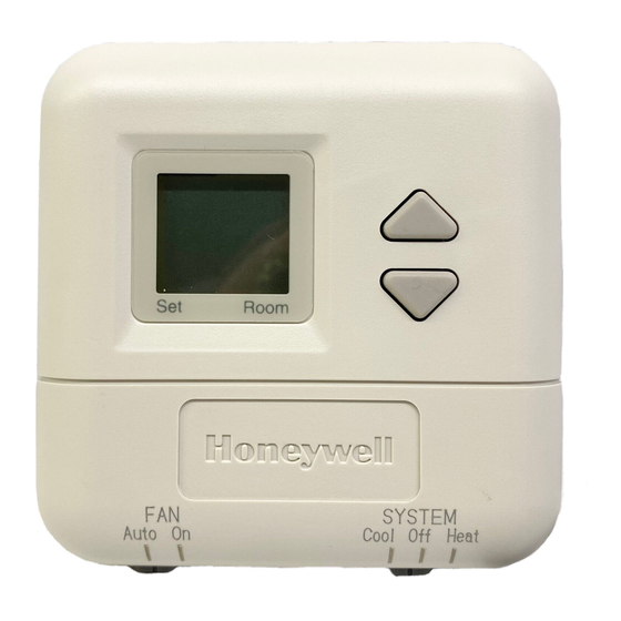
T8400B Thermostat provides single-stage, non-
programmable temperature control for 24V heat-only
applications. Heating cycle rate is selectable at 1, 3, 4,
5, 6, 9, or 12 cph. Temperature indication can be set for
°F or °C.
The T8400B Thermostat is powered through the heating
system controls.
The T8400C and T8401C Thermostats provide single-
stage, non-programmable temperature control for 24V
Heating-cooling systems with manual changeover from
heat to cool. Heating cycle rate is selectable at 1, 3, 6,
9, or 12 cph. Cooling cycle rate is fixed at 3 cph.
Temperature indication can be set for °F or °C.
The T8400C Thermostat is powered through the
heating/cooling system controls. The T8401C Thermo-
stat is powered directly from the system transformer.
Batteries are not required because setpoints are held
permanently by nonvolatile memory for all models.
All models include a thermostat, wallplate (for wiring
and mounting thermostat) and Owner's Guide. Two
decorator cover plates (for covering wall marks) are
included for select models.
MERCURY NOTICE
If this control is replacing a control that contains
mercury in a sealed tube, do not place your old
control in the trash. Dispose of properly.
Contact your local waste management authority
for instructions regarding recycling and the
proper disposal of an old control.
®U.S. Registered Trademark
Copyright © 2002 Honeywell •
Electronic Thermostats
• All Rights Reserved
T8400B,C; T8401C
INSTALLATION INSTRUCTIONS
INSTALLATION
When Installing this Product...
1. Read these instructions carefully. Failure to follow
them could damage the product or cause a
hazardous condition.
2. Check the ratings given in the instructions and on
the product to make sure the product is suitable
for your application.
3. Installer must be a trained, experienced service
technician.
4. After installation is complete, check out product
Operation as provided in these instructions.
CAUTION
Electrical Shock or Equipment Damage
Hazard.
Can shock individuals or short equipment
circuitry.
Disconnect power supply before installation.
Location
Install the thermostat about 5 ft (1.5m) above the floor in
an area with good air circulation at average tempera-
ture. See Fig. 1. Do not install the thermostat where it
can be affected by:
— drafts or dead spots behind doors and in corners.
— hot or cold air from ducts.
— radiant heat from the sun or appliances.
— concealed pipes and chimneys.
— unheated (uncooled) areas such as an outside wall
behind the thermostat.
This thermostat is a precision instrument and was
carefully adjusted at the factory. Handle it carefully.
69-1494-1
Advertisement
Table of Contents

Related Manuals for Honeywell T8400B


Summary of Contents for Honeywell T8400B
- Page 1 °F or °C. 1. Read these instructions carefully. Failure to follow them could damage the product or cause a The T8400B Thermostat is powered through the heating hazardous condition. system controls. 2. Check the ratings given in the instructions and on...
- Page 2 T8400B,C; T8401C ELECTRONIC THERMOSTATS 5 FEET [1.5 METERS] M10308 Fig. 1. Typical location of thermostat. 5-3/4 IN. x 5-3/4 IN. Mounting Wallplate and Decorator Cover DECORATOR COVER PLATE Plate (Select Models) to Wall WALL IMPORTANT Level only for appearance. The thermostat functions normally even when not level.
- Page 3 T8400B,C; T8401C ELECTRONIC THERMOSTATS Wiring The T8400B Thermostat is powered through the heating system control. The T8400B is adaptable to most 2-wire and 3-wire 18 to 30 Vac heating systems. Refer to Fig. 5 IMPORTANT and 6 for typical wiring hookups.
-
Page 4: Setting Fan And System Switches
T8400B,C; T8401C ELECTRONIC THERMOSTATS T8400C, T8401C DASHED LINES INDICATE TABS ON BACK OF THERMOSTAT COOLING CONTACTOR Room Room HEATING RELAY PRIMARY SYSTEM CONTROL Cool Off Heat Auto SYSTEM (HOT) Auto On Cool Off Heat POWER SUPPLY. PROVIDE DISCONNECT MEANS AND... - Page 5 T8400B,C; T8401C ELECTRONIC THERMOSTATS ° ° SYSTEM Switch Setting C Indication and Heat Cycle Rate System switch settings control thermostat operation as follows: NOTE: To save changes to the °F/°C indication and Cool: The thermostat controls the cooling system. the heat cycle rate, all seven steps must be Off: Heating and cooling are off.
- Page 6 T8400B,C; T8401C ELECTRONIC THERMOSTATS CHECKOUT 3. Press the key. Factory information is displayed. A typical example is shown, but information displayed varies by model. This information is for Heating factory use only. 1. Slide the SYSTEM switch to Heat. Slide the FAN switch to Auto, if available.
- Page 7 T8400B,C; T8401C ELECTRONIC THERMOSTATS 69-1494–1...
- Page 8 Automation and Control Solutions Honeywell Honeywell Limited-Honeywell Limitée 1985 Douglas Drive North 35 Dynamic Drive Golden Valley, MN 55422 Scarborough, Ontario M1V 4Z9 www.honeywell.com/yourhome 69-1494–1 G.H. Rev. 2-02 Printed in Mexico...