Table of Contents
Advertisement
Advertisement
Table of Contents

Related Manuals for Husqvarna 968999268


Summary of Contents for Husqvarna 968999268
- Page 1 Operators manual Please read these instructions carefully and make sure you understand them before using the machine. MANUAL NO. 539110972 REV. IR (09/08/04) Models: 968999268 / LZ5225TKAA 968999269 / LZ6123LTKOA 968999270 / LZ6125TKAA 968999271 / LZ6127TKOA 968999272 / LZ7227TKOA...
- Page 2 ©2004 Husqvarna. All rights reserved. Beatrice, NE. Printed in U.S.A.
-
Page 3: Table Of Contents
INTRODUCTION ... 4-5 SYMBOLS & DECALS ... 6 SAFETY INSTRUCTIONS ... 7 General use and safety rules ... 7-8 Driving on slopes ... 9 Children safety... 10 Maintenance safety ... 10-12 Transportation ... 12 ROPS safety ... 13 Customer responsibilities ... 13 PRESENTATION ... -
Page 4: Introduction
INTRODUCTION Introduction Congratulations Thank you for purchasing a Husqvana ride-on mower. This machine is built for the greatest efficiency and rapid mowing of large areas. Convenient controls and a hydrostatic transmission regulated by steering levers also contribute to the machine’s performance. This manual is a valuable document. -
Page 5: Introduction
Good Service Husqvarna’s products are sold all over the world and only in specialized retail stores with complete service. This ensures that you as a customer receive only the best support and service. Before the product is delivered, the machine has, for example, been inspected and adjusted by your retailer, see the certificate in the Service Journal in this operator’s manual. -
Page 6: Symbols & Decals
SYMBOLS AND DECALS Symbols and Decals These symbols are found on the machine and in the operator’s manual. Study them carefully so that you know what they mean. WARNING! Xxxxxxxxxx xxx xxxxx xxxxxxxx. Xxxxxx xxxxx xxxxxxxxx xxxxx xxxxx xxx x xxxxx. Used in this publication to notify the reader of a risk of personal injury, particularly if the reader should neglect to follow instructions given in the manual. -
Page 7: Safety Instructions
Safety Instructions These instructions are for your safety. Read them carefully. WARNING! This symbol means that important safety instructions need to be emphasized. It concerns your safety. General Use • Read all instructions in this operator’s manual and on the machine before starting it. Ensure that you understand them and then abide by them. - Page 8 SAFETY INSTRUCTIONS • Be careful when rounding fixed objects, so that the blades do not hit them. Never drive over foreign objects. • Only use the machine in daylight or in other well-lit conditions. Keep the machine a safe distance from holes or other irregularities in the ground.
-
Page 9: Driving On Slopes
SAFETY INSTRUCTIONS Driving on Slopes Driving on slopes is one of the operations where the risk is greatest that the driver will lose control or the machine will tip over, which can result in serious injury or death. All slopes require extra caution. -
Page 10: Children Safety
SAFETY INSTRUCTIONS Children: • Serious accidents may occur if you fail to be on guard for children in the vicinity of the ma- chine. Children are often attracted to the ma- chine and mowing work. Never assume that children will stay put where you last saw them. •... - Page 11 • Allow the engine to cool before refueling. Do not smoke. Do not fill fuel in the vicinity of sparks or open flames. • If leaks arise in the fuel system, the engine must not be started until the problem has been resolved.
-
Page 12: Transportation
• Never use the machine indoors or in spaces lacking proper ventilation. The exhaust fumes contain carbon monoxide, and odorless, poi- sonous, and lethal gas. • Stop and inspect the equipment if you run over or into anything. If necessary, make repairs before starting. -
Page 13: Rops Safety
SAFETY INSTRUCTIONS Roll Over Protection System This structure’s capability may be imparired by structural damage if overturned, or al- teration occurs. If any of these conditions take place, the total structure MUST be re- placed. DO NOT use ROPS as a lifting, attaching or anchoring point. DO NOT exceed Max GVW: 2822;... -
Page 14: Presentation
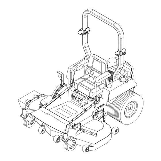
Presentation Thank you for buying a HUSQVARNA! Before operating your new mower, read, understand and follow the safety instructions and other directions in this manual. KEY SWITCH THROTTLE FOOT PLATE HOUR METER PRESENTATION Lawnmowers and all power equipment, can be potentially dangerous if used improperly. -
Page 15: Setup And Adjustments
SETUP AND ADJUSTMENTS WARNING! No settings or adjustments are to be made unless: Engine is stopped, key has been removed, park brake is on and bat- tery cable removed from battery. Setup Uncrate machine. ROPS Assembly (Roll Over Protection System) ROPS Assembly Components 1 - Top Loop 1 - Left Side Post... -
Page 16: Control Arms
SETUP AND ADJUSTMENTS Control Arms Remove top bolt in control arm and loosen bot- tom bolt, rotate the control levers to the upright position. Align the levers so they are even in the neutral position. Reinstall hardware and tighten. FIG - 1 Seat Install 1. -
Page 17: Mower Deck Leveling
SETUP AND ADJUSTMENTS Mower Deck Leveling Position machine on a flat surface. Preferably level concrete. Check the tire pressure in all four tires. Inflation should be 15 psi. Place 2x4’s on edge under the cutting deck from front to rear and lower the deck down onto 2x4’s. Adjust the four lower chain bolts to the center slots on the deck. -
Page 18: Park Brake Adj
SETUP AND ADJUSTMENTS Park Brake Adjustment When the park brake is on, the spring should measure 2 3/4” to2 7/8” and have a 1/4”-3/8” gap between the brake yoke and the washer on the lower brake rod. If the spring needs adjusting follow these steps: 1. -
Page 19: Operating Instructions
OPERATING INSTRUCTIONS Operating instructions Roll Bar and Seat Belt Operate the unit with the roll bar in the raised and locked position and use seat belt. There is no rollover protection when the roll bar is down. If it is necessary to lower roll bar do not wear the seat belt. -
Page 20: Controls
OPERATING INSTRUCTIONS Key Switch Key switch is located on the console. Used to start the machine. NOTE: Do not run the starter for more than 5 seconds at a time. If the engine will not start, wait about 10 seconds before trying again. -
Page 21: Maintenance
Annual inspection and maintenance from an au- thorized Husqvarna dealer is recommended to keep your machine in the best condition mechani- cally and ensures safe operation. Engine oil Should be checked daily before starting the ma- chine. -
Page 22: Hardware
Hardware Check daily. Inspect the entire machine for loose or missing hardware. Air filter See engine manufacturers specifications for cleaning and replacement intervals. Hydraulic system Check oil level in tank daily. Oil level should be 3/ 4” to 1” below the top of the tank. Check all fit- tings, hoses and lines for damage or leaks. -
Page 23: Pump Belt
Pump belt Check belt every 100 hours for excessive wear. To replace belt. Relieve tension on the deck belt and remove deck belt from clutch. See deck belt instructions on previous page. Loosen bolt on the clutch tie down and rotate out of the way. Using a 1/2”... -
Page 24: Torque Specifications
MAINTENANCE Torque Specifications · Engine crankshaft bolt · Deck pulley bolts · Hydraulic tube nuts · Wheel motor hub nut · Lug nuts · Blade bolt · Standard ¼” fasteners · Standard 5/16” fasteners · Standard 3/8” fasteners · Standard 7/16” fasteners ·... -
Page 25: Maintenance Schedule
Maintenance Engine (4) Check oil level Change oil and filter (1) Clean the air filter’s (3) Replace air filter’s (3) Check for fuel and oil leakage Clean cooling flanges (3) Check cooling air inlet Check fuel pump’s air filter Replace fuel filter Replace plugs Hydraulics Check oil level... -
Page 26: Trouble Shooting
PROBLEM ENGINE WILL NOT START. MACHINE WILL NOT MOVE OR MOVES SLOWLY OR HARD. BLADES WILL NOT ENGAGE. UNEVEN CUT CUT IS RAGGED MACHINE VIBRATION TROUBLE SHOOTING Blade switch on. Drive levers not in the neutral slots. Operator not in seat. Park brake disengaged. -
Page 28: Wiring Diagrams
WIRING DIAGRAMS... - Page 29 WIRING DIAGRAMS...