Table of Contents
Advertisement
CHAINTECH
Declaration of Conformity
According to 47 CFR, Parts 2 and 15 of the FCC Rules
9CJS
The following designated product:
EQUIPMENT: MAINBOARD
MODEL NO.: CT-9CJS
Intel® Socket 478
Intel® 875P + ICH5R
ATX Motherboard
is a Class B digital device that complies with 47 CFR Parts 2 and 15 of the FCC
Rules. Operation is subject to the following two conditions:
1. This device may not cause harmful interference.
2. This device must accept any interference received, including interference that
may cause undesired operation.
User's Guide
This declaration is given to the manufacturer:
CHAINTECH-EXCEL COMPUTER INC.
4427 Enterprise St. Fremont, CA 94538, U.S.A.
http://www.chaintechusa.com
Chaintech President: Simon Ho
Signature:
Version 1.0
Advertisement
Chapters
Table of Contents

Related Manuals for CHAINTECH 9CJS


Summary of Contents for CHAINTECH 9CJS
-
Page 1: Declaration Of Conformity
According to 47 CFR, Parts 2 and 15 of the FCC Rules 9CJS The following designated product: EQUIPMENT: MAINBOARD MODEL NO.: CT-9CJS Intel® Socket 478 Intel® 875P + ICH5R ATX Motherboard is a Class B digital device that complies with 47 CFR Parts 2 and 15 of the FCC Rules. -
Page 2: Table Of Contents
Canadian Department of Communications Statement 2-9 CMC (Chaintech Multimedia Card) Setup ........... 30 This digital apparatus does not exceed the Class B limits for audio noise emissions from digital apparatuses BIOS Setup Program ..........32... - Page 3 4-5 USB 2.0 Driver....................63 4-6 WinCinema Pro ..................... 63 Appendix ..................75 A-1 Windows 2000/XP CD-ROM Installation ........... 75 A-2 Intel® Application Accelerator RAID ............76 A-3 Digidoc 80-Port POST Error Code List ............83 How To Contact CHAINTECH ..........89...
-
Page 4: Chapter 1 Introduction
Award system BIOS support PnP, APM, DMI, ACPI, & Multi-device booting - Five 32-Bit PCI slots (v2.2 compatible) features - One CMR (Chaintech Multimedia Raiser) for Chaintech Multimedia Card (CMC) Embedded system monitoring On-board 7.1 Channel audio - 8 external voltage inputs... -
Page 5: Package Contents
Integrates 6 in 1 Card Reader with USB 2.0, IEEE1394, Headphone, - IDE Cable (60cm) Microphone and more - Floppy Cable (60cm) Infrared accompanies with Chaintech Handigator sets you free from 4. Serial ATA cable annoying wires 5. Serial ATA Power Cable Include: 6. -
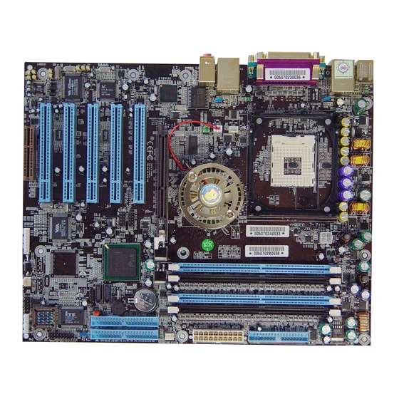
Page 6: 9Cjs Motherboard Diagram
Chapter 1 Chapter 1 1-4 9CJS Motherboard Diagram 1-5 9CJS Motherboard Layout... -
Page 7: Chapter 2 Hardware Setup
Chapter 2 Chapter 2 2-2 Setting your CPU’s Parameters Hardware Setup Chapter 2 “Hyper-Threading Technology” If your motherboard has already been installed in your computer you may still need Basic requirements for Hyper-Threading Technology: to refer to this chapter if you plan to upgrade your system's hardware. CPU: An Intel®... - Page 8 Chapter 2 Chapter 2 This processor will ship under multiple VIDs of 1.475, 1.500, 1.525, and 1.550 with If you install a CPU on this motherboard, you must set the [External Clock Frequency] JP3 according to your processor types (See Section 2.4). 1.550 being the max voltage.
-
Page 9: Main Memory Configuration
Chapter 2 Chapter 2 2-3 Main Memory Configuration Memory Channel Modes This motherboard provides four 184pin Double Data Rate (DDR) Dual-In-line Single Channel / Dual Channel Memory Modules (DIMM) slots, which supports PC 1600/PC2100/2700/3200 DDR Virtual Single Channel SDRAM modules up to 4GB. Install at least one DIMM module on the slots. No restrictions Matching DIMM pairs DIMM Population... - Page 10 Chapter 2 Chapter 2 The following conditions must be met: Maximizing Performance –Matched DIMM configuration in each channel Optimal configurations for highest performance: •Same Density (128MB, 256MB, 512MB, etc.) –Matched, DDR400, Double-sided DIMMs •Same DRAM technology (128Mb, 256Mb, or 512Mb) –Dual Channel Mode (Symmetrical DIMM population) •Same DRAM bus width (x8 or x16) •Both either single-sided or dual-sided...
-
Page 11: Connector And Jumper Reference Chart
IDE1 / 2 IDE Hard-Disk Connector make sure it is not connected to the power source. CMOS Clear Jumper All cables that provided by CHAINTECH come with a security-proof. Disable/Enable USB 0/1, 2/3 Device Power ON JP6 / 6A Jumper... -
Page 12: Cn1A
Chapter 2 Chapter 2 Blinking LED in Suspend Mode: 2. P-LED (Power LED Connector): While in Suspend mode, the LED light on the front panel of your computer will The power indicator LED shows the system's power status. It is important to pay flash. -
Page 13: Ide1 / 2 Ide Hard-Disk Connector
Chapter 2 Chapter 2 IDE 1/2 (IDE Hard-Disk Connector) 3. Connect the system's power and then start the system. 4. Enter BIOS's CMOS Setup Utility and choose Load Setup Defaults. Type [Y] and then press [Enter] to continue. 5. Set the system configuration in the Standard CMOS Setup menu. JP6/JP6A (Enable/Disable USB 0/1, 2/3 Device Power ON Jumper) Definition Disable (default) -
Page 14: Cn17 Blue Led Connector (5V)
Chapter 2 Chapter 2 manufacturer. On standard fans, the red is positive (+12V), the black is ground, and provides WOM function to the motherboard. the yellow wire is the rotation signal. Connect the north-bridge cooling fan to FAN3. CN17 (Blue LED Connector) CN5 [WOL (Wake-on-LAN) Connector]: Enable the Wake Up On LAN selection in BIOS's Power Management Menu to use this function. -
Page 15: Cn24 Cbox™3 Front Audio Connector
CN26B (IEEE1394 Connector) CN25 (CBOX™ 3 DigiDoc System Display Connector): CBOX™ 3 features CHAINTECH’s exclusive DigiDoc, the most advanced system Attach the IEEE 1394 serial connector cable to the IEEE 1394 bracket, and the diagnostic monitoring display. -
Page 16: Serial Ata And Parallel Ata
Chapter 2 Chapter 2 JP3 / 3A (CPU Front Side Bus setting) 2-6 Serial ATA and Parallel ATA SATA & PATA configurations JP3A Definition 1. Compatible mode - Default Older OSs don’t support switch to native mode (DOS, Win2K, Win98/ME…) should set SATA and PATA to Compatible Mode. -
Page 17: Cbox™ 3 Setup
Front Audio Cable (10 pin) IEEE-1394 Cable (8 pin) 80 Port Display (10 pin) (3c) (3d) Enhanced Mode Enable S-ATA & P-ATA Max 6 ATA (4 ATA + 2 ATA) All cables that provided by CHAINTECH come with a security-proof. -
Page 18: Handigator: Function List
Chapter 2 Chapter 2 2-8 Handigator: Function List 2-9 CMC (Chaintech Multimedia Card) Setup CN2/CN2A (CD-ROM Audio-in Connector) KEY NO. Function KEY NO. Function Turn on/Off PC Volume Down Open Browser Mute Open Email Page Up Search in WWW Page Down... -
Page 19: Chapter 3 Bios Setup Program
Chapter 2 Chapter 3 BIOS Setup Program Chapter 3 CN3 (Auxiliary Audio-In Connector) Phoenix-Award BIOS ROM has a built-in setup program that allows users to modify the basic system configuration. This information is stored in CMOS RAM so that it can retain the setup information even when the power is turned off. -
Page 20: Standard Cmos Setup
Chapter 3 Chapter 3 3-1 Standard CMOS Setup POST (Power On Self Test). This function stops the computer if BIOS detects a The Standard CMOS Setup allows users to configure system components such as hardware error. You can tell BIOS to halt on all errors, no errors, or not to halt on hard-disk drive, floppy-disk drive and video display as well as date, time and boot specific errors. - Page 21 Chapter 3 Chapter 3 Hyper-Threading Technology 2. Typematic Rate (Chars/Sec) Available options are [Enabled] and [Disabled]. Select [Enable] to support The typematic rate sets the rate at which characters on the screen repeat when a key Hyper-Threading Technology and vice versa. is pressed and held down.
-
Page 22: Advanced Chipset Features
Chapter 3 Chapter 3 3-3 Advanced Chipset Features DRAM RAS# Precharge By choosing the [Advanced Chipset Features] option from the CMOS Setup This item controls the idle clocks after issuing Precharge command to the DRAM. Utility menu (Figure 3-1), the screen below is displayed. This sample screen Memory Frequency For contains the manufacturer's default values for the motherboard. -
Page 23: Integrated Peripherals
Chapter 3 Chapter 3 The remaining memory, which is not in use, will be available for the system. For example, if 16MB is allocated to the AGP card and the card only needs 8MB, the 1. IDE HDD Block Mode remaining 8MB will be available for system use. - Page 24 Chapter 3 Chapter 3 Press [Enter] to enter the sub-menu, which contains the following items for some Onboard Device: advanced controls: This section provides information for setting the on-board devices. By choosing the Integrated Peripherals option from the CMOS Setup Utility menu (Figure 3-5), the 1.
-
Page 25: Power Management Setup
Chapter 3 Chapter 3 3-5 Power Management Setup synchronization ports, writes blanks to the VGA buffer and the monitor's This section provides information on the Green PC power management functions. electron gun turns off. This function requires monitors with Green features in By choosing the Power Management Setup option from the CMOS Setup Utility order to take advantage of the power-saving function. -
Page 26: Pnp/Pci Configurations
Chapter 3 Chapter 3 2. Power On by Modem: 3-6 PNP/PCI Configurations This section provides IRQ and DMA setting information. By choosing the PNP/PCI When enabled, a Modem will be able to receive a signal and activate the system Configuration option from the CMOS Setup Utility menu (Figure 3-1), the screen from soft off and green mode. -
Page 27: Pc Health Status
Chapter 3 Chapter 3 FDD IRQ Can Be Free: 3-8 Frequency/Voltage Control This function allows users to choose if the FDD IRQ can be freed up. The default By choosing the Frequency/Voltage Control option from the CMOS Setup Utility setting is [Yes] and this does not allow the IRQ to be free. menu (Figure 3-1), the screen below is displayed. -
Page 28: Load Fail-Safe Defaults
Chapter 3 Chapter 3 Voltage Fine Tune 3-12 Save and Exit Setup Please leave the default setting as [Disable] for a stable system operation. Available If you select this and type [Y] (for Yes) followed by the [Enter] key, the values options are [Enabled] and [Disabled]. -
Page 29: Chapter 4 Driver Setup
Chapter 4 Chapter 4 3. Click [Yes] to accept the license agreement. DRIVER Setup Chapter 4 Insert the support CD that come with your motherboard into your CD-ROM driver or double-click the CD drive icon in [My computer] to enter the setup screen. 4-1 Intel®... -
Page 30: Sata Driver
Chapter 4 Chapter 4 5. Please select [Yes] to restart computer now or [No] to restart later, and then click 2. Click [Next>] to continue the setup process. on [Finish] to complete the installation. 3. After reading the license agreement, please click [Yes] to continue. 4-2 SATA Driver Please refer to Section 2-6 Serial ATA and Parallel ATA and Section 3.4 Integrated Peripherals ->... -
Page 31: Audio Driver
Chapter 4 Chapter 4 4. Please select a folder where the program will be installed and click on [Next >] to 6. Click [Finish] to complete the setup process. proceed. Please refer to Appendix for overview on Intel® Application Accelerator RAID. 4-3 Audio Driver 5. - Page 32 Chapter 4 Chapter 4 2. Click [Next] to start software installation. 4. Select [7.1 speakers] and click [Next>] to continue. This option is only available when users install Windows XP SP 1 or its later versions. The option [5.1 speakers] is available when Windows 2000 or its previous versions (ie Win 2000, Win NT, Win Me and Win 9x) are installed.
-
Page 33: Intel® Lan Driver Setup
Chapter 4 Chapter 4 6. Please select [Yes] to restart computer now or [No] to restart later, and then click 2. Select [Next >] to continue. on [Finish] to complete the installation. 3. Click [Finish] to complete the setup process. 4-3 Intel®... -
Page 34: Gigabit Lan Driver
Chapter 4 Chapter 4 4-4 Gigabit Lan Driver 3. Click [Install Base Driver]. 1. Select [Gigabit LAN Driver]. 4. Click [OK] to continue. 2. Click [Wired LAN Adapters]. 5. Click [Exit] to complete the setup process. -
Page 35: Usb 2.0 Driver
Chapter 4 Chapter 4 4-5 USB 2.0 Driver 2. Select [Install InterVideo WinCinema]. Open Device Manager and open the properties for the USB 2.0 host controller. Select 'Update Driver'. Point the installer to the folder with the USB 2.0 drivers. It should select from CD-ROM:\intel\usb2\win2k_XP\ich5usb2_win2k (for Win 2000 /XP) or CD-ROM:\intel\usb2\win98&me (for 98se / ME) and then install the system files. - Page 36 Chapter 4 Chapter 4 4. Choose [Select All] to select all the products, in this case WINDVD and WINRIP, 2. After reading the license agreement, please click [Yes] to continue. and [Clear All] to deselect them. Click [Next >] to proceed. 3.
- Page 37 Chapter 4 Chapter 4 4. Please select one folder name from existing list of folders and click on [Next >] to 6. Please check the box to install the help file and click on [Next>] to proceed. proceed. 5. Please select the default player by checking the specific boxes and click on [Next>] 4.6.2 WinRip 2.1 Setup to proceed.
- Page 38 Chapter 4 Chapter 4 2. After reading the license agreement, please click [Yes] to continue. 4. Please select one folder name from existing list of folders and click on [Next >] to proceed. 3. Please select a folder where the program will be installed and click on [Next >] to proceed.
- Page 39 Chapter 4 Chapter 4 6. Choose [Select All] to select all file extension types for WinRip and click on 8. Select [Yes] to continue. [Next >] to continue. 9. Click on [Finish] to complete the configuration process. 7. Click on [Next >] to continue.
- Page 40 Chapter 4 Chapter 4 10. Click on [Finish] to complete the setup. 12. Select [Yes] to exit now or [No] to go back to Main Menu. 11. Please select [Yes] for restarting computer now or [No] for restart later, then click on [Finish] to complete installation.
-
Page 41: Appendix
Appendix Appendix A-2 Intel® Application Accelerator RAID Appendix A-1 Windows 2000/XP CD-ROM Installation Please refer to Section 2-6 Serial ATA and Parallel ATA and Section 3-4 Integrated Peripherals -> OnChip IDE Device -> OnChip Serial ATA for details. 1. Start the Windows 2000/XP installation by booting from the Windows 2000/XP CD-ROM: The system BIOS must support booting from a CD-ROM. - Page 42 Appendix Appendix Windows* XP*. RAID 0 Advantage: Highest transfer rates Software installation is flexible and fully automated for Microsoft Windows XP RAID 0 Disadvantage: No redundancy – if one disk fails, all data will be lost Home Edition and Windows XP Professional operating systems. RAID 0 Application: Typically used in workstations for temporary data and high * Other brands and names may be claimed as the property of others.
- Page 43 Appendix Appendix displays information about your system’s RAID configuration as viewed by the entries for the Intel® Ultra ATA controller and all connected ATA devices. Intel® Application Accelerator RAID Edition application. The ability to create, view, Selecting a particular controller or device in the Devices window causes the and delete RAID volumes is provided.
- Page 44 Appendix Appendix system but the disk itself is not. Number of Disks Number of disks contained in the RAID volume None Member Disks Lists the disks contained in the RAID volume Disk has meta-data on it that keeps it from being exported to the operating system but it is not an array member Component Overview: Create, View and Delete RAID Volumes Navigation Note: You can right mouse click on a device for actions:...
-
Page 45: Digidoc 80-Port Post Error Code List
Appendix Appendix before you delete a volume. Program chipset default values into chipset. Chipset default values are MODBINable by OEM customers. Modify a Volume Initial Early_Init_Onboard_Generator switch. You can modify the volume name by right clicking on a volume and selecting “Modify”. - Page 46 Appendix Appendix 2. Auto assign ports to onboard COM ports if the corresponding Test 8254 item in Setup is set to “AUTO”. Test 8259 interrupt mask bits for channel 1. 1. Initialize floppy controller. Test 8259 interrupt mask bits for channel 2. 2.
- Page 47 4. Load CMOS time into DOS timer tick. appear in this manual to their original owners. 5. Build MSIRQ routing table. Boot attempt (INT 19h) CHAINTECH reserves all the rights to change this manual. All information is subject to change without notice.
-
Page 48: How To Contact Chaintech
How To Contact CHAINTECH How To Contact CHAINTECH Please do not hesitate to contact us if you have any problem about our products. Any opinion will be appreciated. For Asia, Africa, Australia and Pacific Island: For UK: CHAINTECH COMPUTER CO., LTD CHAINTECH UK., LTD.