Table of Contents
Advertisement
Quick Links
Declaration of Conformity
9BIL3
According to 47 CFR, Parts 2 and 15 of the FCC Rules
The following designated product:
Intel Socket 478
Intel 845D + ICH2
EQUIPMENT: MAINBOARD
MODEL NO.: 9BIL3
u-ATX Motherboard
is a Class B digital device that complies with 47 CFR Parts 2 and 15 of the FCC
Rules. Operation is subject to the following two conditions:
User's Guide
1. This device may not cause harmful interference.
2. This device must accept any interference received, including interference that
may cause undesired operation.
This declaration is given to the manufacturer:
CHAINTECH-EXCEL COMPUTER INC.
Version 1.0
4427 Enterprise St. Fremont, CA 94538, U.S.A.
http://www.chaintech-excel.com
Chaintech President: Simon Ho
Signature:
Advertisement
Table of Contents

Related Manuals for CHAINTECH 9BIL3


Summary of Contents for CHAINTECH 9BIL3
- Page 1 Intel Socket 478 Intel 845D + ICH2 EQUIPMENT: MAINBOARD MODEL NO.: 9BIL3 u-ATX Motherboard is a Class B digital device that complies with 47 CFR Parts 2 and 15 of the FCC Rules. Operation is subject to the following two conditions: User’s Guide...
-
Page 2: Table Of Contents
15 of the FCC Rules. These limits are designed to provide reasonable protection against harmful interference in a 1-3 9BIL3 Motherboard Layout.................. 2 residential installation. This equipment generates, uses, and can radiate radio frequency energy. If this equipment is not installed and used in accordance with the manufacturer's instructions, it may cause harmful interference to radio Hardware Setup.............3... -
Page 3: Chapter 1 Introduction
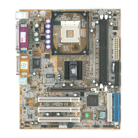
Chapter 1 Chapter 1 1-3 9BIL3 Motherboard Layout Introduction Chapter 1 1-1 Product Specifications Processor Supports Intel Celeron/Pentium 4 Socket 478 CPU Page 6 Supports Intel Celeron/Pentium 4 system bus at 400/533MHz Chipset Page 6 Intel 845D + ICH2 Page 4... -
Page 4: Chapter 2 Hardware Setup
Chapter 2 Chapter 2 DDR SDRAM Specifications Hardware Setup Chapter 2 DIMM type: 2.5V, 184-pin unbuffered PC1600/2100 DDR SDRAM. Module size: Single/double-sided 64/128/256/512Mbytes or 1GBytes. If your motherboard has already been installed in your computer you may still need to Parity: Either parity or non-parity. - Page 5 Chapter 2 Chapter 2 When the Soft-OFF by PWR-BTTN function is enabled, pushing the power button JP6 (Enable/Disable USB 0/1 Device Wake-Up Jumper) rapidly will switch the system to Suspend mode. Any occurrence of external activities such as pressing a key on the keyboard or moving the mouse will bring the system A USB keyboard hot key or a USB mouse click can Definition back to Full-On.
-
Page 6: Chapter 3 Bios Setup Program
Chapter 2 Chapter 3 BIOS Setup Program CN24 (Front Audio Connector) Chapter 3 This connector give you the option of a front panel audio jack Phoenix-Award BIOS ROM has a built-in setup program that allows users to modify cable ext. to be plug into a special custom designed system case. the basic system configuration. -
Page 7: Advanced Bios Features
Chapter 3 Chapter 3 Video Gate A20 Option: Select the type of video adapter present in your system. You can ignore this setting if This allows you to set the Gate A20 status. When set to [Fast], Gate A20 is cont rolled you are using a VGA monitor;... -
Page 8: Advanced Chipset Features
Chapter 3 Chapter 3 3-3 Advanced Chipset Features AGP Aperture Size By choosing the [Advanced Chipset Features] option from the CMOS Setup Utility This function determines the amount of system memory that is given to the AGP card. menu (Figure 3-1), the screen below is displayed. This sample screen contains the Options range from 4MB to 256MB. -
Page 9: Power Management Setup
Chapter 3 Chapter 3 2. AC97 Modem your system has no USB keyboard, select Disabled in this field. This item allows you to enable/disable the MCP chipset’s feature to support MC97 Init Display First Modem. This function allows users to choose AGP or PCI slot to initialize display. Super IO Device CIR Port Address This section provides information on setting Super I/O device. -
Page 10: Pnp/Pci Configurations
Chapter 3 Chapter 3 MODEM Use IRQ 8. Hot Key Power On Available options: [Ctrl-F1] through [Ctrl-F12]. If your computer has a modem use this function to tell BIOS which IRQ is being occupied by the modem card. When the system is in Green mode, the modem requires an IRQ assignment to wake up the system and perform tasks. -
Page 11: Load Fail-Safe Defaults
Chapter 3 Chapter 4 Overclocking: DRIVER Setup Chapter 4 This motherboard is designed to support overclocking. However, please make sure your components are able to tolerate such abnormal setting, Insert the support CD that come with your motherboard into your CD-ROM driver or while doing overclocking. -
Page 12: Audio Driver Setup
Chapter 4 NOTE driver. To avoid some issues after proceeding to operating system. 4-3 Audio Driver Setup 1. Click [Audio Driver] NOTE 2. Click [Next >] to continue installation 3. Click [Finish] to complete setup. 4-4 LAN Driver Setup 1. Click [LAN Driver] All rights are reserved for the products and corporate names/logos that 2. - Page 13 How To Contact CHAINTECH How To Contact CHAINTECH Please do not hesitate to contact us if you have any problem about our products. Any opinion will be appreciated. For Asia, Africa, Australia and Pacific Island: For UK: CHAINTECH COMPUTER CO., LTD CHAINTECH UK., LTD.