Philips PET702 Service Manual
Hide thumbs
Also See for PET702:
- Service manual (34 pages) ,
- Specifications (2 pages) ,
- User manual (2 pages)
Advertisement
Quick Links
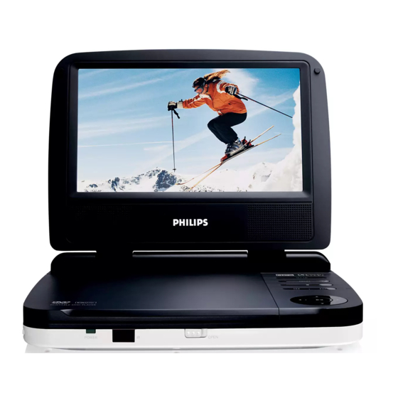
DVD Portable Player
Service Manual
TABLE OF CONTENTS
Safety Instructions..................................................... 2
Instruction for Use...................................................... 3
Mechanical Instructions.............................................. 4
Troubleshooting .........................................................5
Overall Block Diagram................................................. 6
Electrical Diagram...................................................... 7
Component Layout Diagram........................................ 8
Service Part List.......................................................... 9
Revision List............................................................. 10
©Copyright 2005 Philips Consumer Electronics B.V. Eindhoven, The Netherlands
All rights reserved. No part of this publication may by reproduced, stored in a
retrieval system or transmitted, in any form or by any means, electronics,
mechanical, photocopying, or otherwise without the prior permission of Philips
Version 1.3
PET702
All version
Chapter
3141 785 32053
Advertisement

Related Manuals for Philips PET702


Summary of Contents for Philips PET702
-
Page 1: Table Of Contents
All rights reserved. No part of this publication may by reproduced, stored in a retrieval system or transmitted, in any form or by any means, electronics, mechanical, photocopying, or otherwise without the prior permission of Philips 3141 785 32053 Version 1.3... -
Page 2: Technical Specification
1.0 TECHNICAL SPECIFICATION General Playback disc type: DVD, Picture-CD, SVCD, Video CD, MP3- CD, CD-R/CD-RW, WMA-CD, DVD-R, DVD- Dimensions (W x H x D): 210 x 178 x 39mm RW, DVD+R, DVD+RW Bear Unit Weight: 719.3g +/- 5% Power supply: Input: 100-240V AC, 50/60Hz Video Playback Format: DVD / VCD / JPEG... - Page 3 For the best performance of your DVD Portable. Check www.philips.com/support for latest software upgrades available. A) By CD-ROM Download the “PHILIPS.BIN” file from the Philips support site Unzip the file and then burn it into a CD-ROM to make a disc for upgrade CD-ROM disc name must be “PHILIPS”...
- Page 4 2.0 SAFTETY INSTRUCTIONS WAARSCHUWING WARNING Alle IC’s en vele andere halfgeleiders zijn All ICs and many other semi-conductors are gevoelig voor electrostatische ontladingen susceptible to electrostatic discharges (ESD). (ESD). Careless handling during repair can reduce life Onzorgvuldig behandelen tijdens reparatie kan drastically.
- Page 5 2.1 ESD PROTECTION When the power supply is being turned on, you may not remove this laser cautions label. If it removes, radiation of laser may be received. PREPARATION OF SERVICING Pickup Head consists of a laser diode that is very susceptible to external static electrocity. Although it operates properly after replacement, if it was subject to electrostatic discharge during replacement, its life might be shortened.
- Page 6 SAFTY NOTICE SAFTY PRECAUTIONS LEAKAGE CURRENT CHECK Plug the AC line cord directly into a 120V AC outlet (do Measure the AC voltage across the 1500 resistor. not use an isolation transformer for this check). Use an The test must be conducted with the AC switch on and AC voltmeter, having 5000 per volt or more sensitivity.
-
Page 7: Instruction For Use
3.0 INSTRUCTION FOR USE... -
Page 8: Mechanical Instructions
4.0 MECHANICAL INSTRUCTION 1. Remove 8pcs of screws on the side of bottom cabinet. 2. up-plug all the wire connecter from main board, The wire connectors are for: DVD loader, battery board and TFT driver board, and speaker. 3. up-plug the FFC from DVD driver, then you can take out the DVD Driver. - Page 9 4.0 MECHANICAL INSTRUCTION 6. Remove 6pcs screws from key board. 7. Remove 6pcs of screws on the display frame. Carefully open display frame with catches screwdriver.( There are six catches as shown in the pictures) Then you can see next picture. To remove the TFT, de-soldering the wire connected between TFT and TFT board first.
-
Page 10: Troubleshooting
5.0 TROUBLESHOOTING SYMPTOM: BATTERY NO POWER BATTERY CAN'T Power ON Start Check charging Check adaptor Check Battery capacity? SET OK? function OK? power-ON OK? Check the Power-ON No Defect, return button and cable OK? set to Customer Replace Button or Replace Main Board Cable... - Page 11 5.0 TROUBLESHOOTING SYMPTOM: NO IMAGE / NO SOUND SYMPTOM: NO IMAGE OUTPUT ( THE PANEL SHOW BLUE PICTURE) Start Check DVD Drive work? Replace DVD Drive Check the external AV NOTE: AV Cable TYPE from outside to note Cable TYPE Exchange AV cable Inside L-Audio, R-Audio, Video, Ground connection is OK?
- Page 12 5.0 TROUBLESHOOTING SYMPTOM: THE DVD DRIVE DOES NOT WORK SYMPTOM: THE DVD DRIVE DOESN'T WORK Start Check DVD-Loader Cable Reinsertion connection OK? Check the DVD-Loader Replace DVD- Loader Replace main board...
- Page 13 5.0 TROUBLESHOOTING SYMPTOM: ADAPTOR CANNOT POWER ON Adaptor can not Power ON Start Check Adaptor OK? Change adaptor SET OK? Check the Power-ON Return set to Replace Main Board button and cable OK? Customer Replace Button or Cable...
- Page 14 5.0 TROUBLESHOOTING SYMPTOM: REMOTE CONTROL CANNOT WORK SYMPTOM: THE REMOTE CONTROL CAN NOT WORK Start Check CABLE form bottom board to top board Cable Reinsertion connection OK? Check TOP-board OK? Replace IR receiver Replace top board Replace main board Return to custormer...
- Page 15 5.0 TROUBLESHOOTING SYMPTOM: NO SOUND FROM HEADPHONE...
- Page 16 5.0 TROUBLESHOOTING SYMPTOM: LED DISPLAY FAILURE SYMPTOM: LED Display Fail Start Check CABLE form Main board to top board Cable Reinsertion connection OK? Check TOP-board OK? Replace LED Replace top board Replace main board Return to custormer...
- Page 17 5.0 TROUBLESHOOTING SYMPTOM: KEY & BOTTON FAILURE SYMPTOM: Key & Botton Fail Start Check CABLE form board to Cable Reinsertion board connection OK? Check KEY board OK? Replace KEY board Replace main board Return to custormer...
- Page 18 6.0 BLOCK DIAGRAM...
-
Page 19: Electrical Diagram
AR35 -12V_VOP AC16 AC37 89P VCOM DAC OUTPUT 22uH SSD03 0.1uF 10uF/25V/1206 AR61 AC15 AR30 AC14 AR33 AU2A AR28 VCOM LG&PHILIPS LT070W02 0.1uF 0.1uF 89KP_VCOM AR34 AC11 AC12 CSC3414A DMP8 HWCAT AR59 AC38 AC24 0.1uF 0.1uF 10uF/16V 0.1uF 10uF/16V(A) 10uF/16V(A) - Page 20 7.0 Electrical Diagram - Main board R105 C102 100pF AOUT_L AOUT_L R107 AOUT_R AOUT_R C103 1uF/0805 R106 5.1K R109 AOUT_L EC33 10uF/16V R108 330R MUTE_DAC MUTE_DAC AV-OUT-L AV-OUT-L A_L_SPEAKER R110 C104 AV/OUT-JACK JACK1 NJM4558-SOP-8 C105 5.6K 1000pF A_MUTE AV-OUT-L FB2K2 820p 3904/nc R111...
- Page 21 7.0 Electrical Diagram - Main board SDRAM (Dual Layout) DV33 SD33 DV33 DV33 SD33 EC31 EC32 DCLK DCLK 100uF/6.3V 100uF/6.3V 0.1uF 0.1uF 0.1uF CAS# CAS# RAS# RAS# SD33 SDCKE SD33 MA[0..11] MA[0..11] MA10 DQ10 DCS# MA10 DQ10 DQM[0..1] DQM[0..1] DQ10 A10/AP DQ10 DBA0...
- Page 22 7.0 Electrical Diagram - Main board 89L_3V3 89L_3V3 V1P4 DV33 RFVDD3 RFV18-1 150uH ADACVDD RFVDD3 RFV18-1 ADACVDD EC21 EC22 100k APLLVDD3 0.1uF 10uF/16VSMD 0.1uF 10uF/16VSMD APLLVDD3 10uF/6.3VSMD 0.1uF 0.1uF DACVDD3 DACVDD3 RF Reference AVDD33 RFV18-2 EC23 AVDD33 RFV18-2 10uF/6.3VSMD 27MHz 0.1uF 0.1uF 0.1uF...
- Page 23 7.0 Electrical Diagram - Main board battery charge BATTERY SI2307 +9VDCIN CHARGE 22k 1% DC_IN 100R B-CHARG 0.1uF/NC 0.1uF/NC 3904 100uF/16V 3904 910 1% 0.1uF CHARGE ON INDICATION MPS2264/TSSOP20F/NC switchpower 11.5K/1%/NC C4 0.47uF/NC POWER ON 10k/NC 2.2nF/NC ON/OFF B-CHARG COMPA POWER OFF 0.1u 30K/1%NC...
- Page 24 7.0 Electrical Diagram - Charge board...
- Page 25 7.0 Electrical Diagram - KEY board PREV. MENU KEY1 KEY2 KEY1 NEXT KEY2 KEY2 SOURCE KEY3 KEY3 monitor KEY4 KEY4 PLAY/PAUSE KEY2 KEY3 KEY1 DOWN LEFT KS10 RiGHT KEY4 Title PET702KEY Size Document Number <Doc> <RevCode> Date: Sunday, August 12, 2007 Sheet...
-
Page 26: Component Layout Diagram
8.0 Component Layout Diagram - TFT & Charge board (Top View) - Page 27 8.0 Component Layout Diagram - TFT & Charge board (Bottom View)
- Page 28 8.0 Component Layout Diagram - Key Board (Top View)
- Page 29 8.0 Component Layout Diagram - Key Board (Bottom View)
-
Page 30: Service Part List
Service Description Photo Pos. 12NC 996510007683 MAIN PCB ASSY PET702/98 996510009482 MAIN PCB ASSY PET702/75 MAIN PCB ASSY PET702/55, /77, 996510012231 996510007684 KEY PCB ASSY PET702/98, /75 KEY PCB ASSY PET702/55, /77, 996510012232 TFT DRIVER PCB ASSY 996510007694 PET702/98, /75... - Page 31 996510012234 PET702/55, /77, /12 DISPLAY FRAME & SPEAKER 996510007693 PET702/98, /75 DISPLAY FRAME & SPEAKER 996510012237 PET702/55, /77, /12 996510007692 MIDDLE CABINET PET702 996510004278 CD DOOR PET702/98 996510009485 CD DOOR PET702/75, /55, /77, /12 996510007690 LENS PET702 996510002356 HINGE PET702...
- Page 32 PET702/75, /55, /77, /12 996510004273 OK BUTTON PET702/98 OK BUTTOM 996510009483 PET702/75, /55, /77, /12 996510004274 KEY ASSY PET702/98 996510009484 KEY ASSY PET702/75 996510012235 KEY ASSY PET702/55, /77, /12 996510007682 OPEN BUTTON PET702 996510007689 OPEN SPRING PET702/98, /75 DOOR SPRING PET702/55, /77, 996510010454...
- Page 33 9.0 SERVICE PART LIST Accessories Part List: Service Service Description Photo Pos. No. 12NC 996510004973 AC/DC ADAPTER FOR PET702/37 996510002353 AC/DC ADAPTER FOR PET702/98 AC/DC ADAPTER FOR 996510010378 ACADAPTOR PET702/12, PET702/55 996510012239 AC ADAPTER PLUG PET702/55 996510012247 AC/DC ADAPTER FOR PET702/77...
-
Page 34: Revision List
Section 9 - Add spare part for PET702/75 Version 1.2 (3141 785 32052) • Section 9 - Add spare part for PET702/55 and PET702/77 Version 1.3 (3141 785 32053) • Section 9 - Add spare part for PET702/12, remove car mount 996510012446...