Table of Contents
Advertisement
Quick Links
Advertisement
Table of Contents

Related Manuals for Alinco DJ-X2000


Summary of Contents for Alinco DJ-X2000
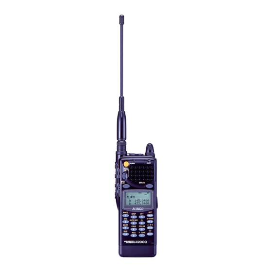
- Page 1 WIDE RANGE SCANNING RECEIVER DJ-X2000 Instruction Manual Thank you for purchasing the ALINCO receiver. The DJ-X2000 instruction C L R manual contains important safety and operating instructions. Read this manual carefully before using the product.
- Page 2 Features The Alinco DJ-X2000 is a professional multifunctional receiver which covers a wide band of radio media from the low-frequency band (LF) to ultrahigh- frequency (UHF) band. It has the following features. 1. Wide frequency range The DJ-X2000 covers the wide frequency range from 0.1 to 2149.999950 MHz.
- Page 3 The DJ-X2000 can return scrambled voice transmission to a normal voice reception. 15. Flash tune If there are signals around the DJ-X2000, it tunes in the strongest frequency in a flash. This function allows you to use the DJ-X2000 as a radio 16.
-
Page 4: Table Of Contents
1.3.1 Top, front and left side panels 1.3.2 Rear and right panels 1.3.3 Display 1.3.4 Key pad 1.4 Setting up the DJ-X2000 1.4.1 Attaching the antenna 1.4.2 Attaching the belt clip 1.4.3 Attaching the wrist strap 1.5 About the batteries 1.5.1 Attaching the battery pack... - Page 5 2.13.2 Setting the ON timer 2.14 Basic modes 2.14.1 VFO mode 2.14.2 PMS mode 2.14.3 MR mode 2.15 Using HELP menu 3. Other Useful Functions 3.1 Functions common to all modes 3.1.1 Selecting a signal mode 3.1.2 Setting the frequency step 3.1.3 Attenuating interference from other cannels(ATT) 3.1.4 Battery Save 3.1.5 Copying data between two receivers(CLONE)
- Page 6 3.1.30 Transceiver function 3.1.31 Directly changing the settings Functions in the VFO mode 3.2.1 VFO link function 3.2.2 Scanning between VFO's A and B(AB SCAN) 3.2.3 Copying frequencies from memories to the VFO 3.2.4 Copying frequencies from the PMS mode to the VFO 3.3 PMS mode functions 3.3.1 Programmed scan operations 3.3.2 Setting scan pass-frequency...
-
Page 7: How To Read This Manual
How to read this manual The following typographical and graphic conventions are used in this instruction manual. Bold typeface indicates titles of chapters and sections as well as messages shown on the display. When used to indicate displayed messages, only the part of the message that is pertinent to the explanation is given. - Page 8 FOR HOME OR OFFICE USE Information in this document are subject to change without notice or obligation.All brand names and trademarks are the property of their respective owners. Alinco cannot be liable for pictorial or typographical inaccuracies. Some parts, options and/or accessories are unavailable in certain areas.
-
Page 9: Before Use
• If the receiver emits smoke or strange odors, shut power OFF immediately and promptly contact an authorized dealer. • Do not disassemble or tamper with the receiver. The DJ-X2000 is not warranted for troubles or accidents resulting from unauthorized modifications, regardless of the warranty period. -
Page 10: Names Of Parts And Their Funciotns
1.3 Names of parts and their functions This section describes parts by name and function. 1.3.1 Top, front and left side panels C L R 1. Dial Use to switch frequency and memory channel, to adjust the audio volume and squelch level, and to make other settings. - Page 11 20. Built-in microphone Use to pick up the sound and record it, or use in transceiver mode. Note: PTT (Press to talk) key is usually attached to a transceiver. In the DJ-X2000, SRCH key is used as a PTT key in transceiver mode. You can transmit a signal while PTT key is held down, or every press of PTT key switches between transmission and reception.
-
Page 12: Rear And Right Panels
1. DC-IN Connect an external DC supply here (10 - 16 V). 2. Holes for attaching belt clip Screw the included belt clip to the DJ-X2000 here. 3. Battery case lock Slide to the right to detach the battery case. -
Page 13: Display
1.3.3 Display Meter for displaying sound level. Displayed when the key has been pressed to indicate that you can access the subfunctions of the keys. 3. PRIO Displayed while the priority function is ON. 4. M Displayed in the MR mode. 5. -
Page 14: Key Pad
1.3.4 Key pad MODE Inputs 1. Press in combination with the key to switch the radio band. STEP Inputs 2. Press in combination with the key to set frequency step. Inputs 3. Press in combination with the key to turn the attenuator ON/OFF. -
Page 15: Setting Up The Dj-X2000
1.4 Setting up the DJ-X2000 Before using your receiver, attach the included antenna securely. If wanting to use the belt clip or wrist strap, attach them too. 1.4.1 Attaching the antenna Fit the base of the antenna over the projections on the connector, press downward and turn clockwise. -
Page 16: About The Batteries
• To attach the battery pack Fit the battery pack into the holes on the DJ-X2000 and push in the direction of the arrow until the case snaps into the place. -
Page 17: About The Battery Pack
Before using the included EBP-37N battery pack, please note the followings. 1. The battery pack is not charged before it is shipped from the factory. Charge the pack before using the DJ-X2000 for the first time. 2. Approximately 1 hour is required to fully charge the battery pack with the charger. -
Page 18: Ni-Cd Batterypack
1.5.3 Ni-Cd battery pack The supplied battery charger is designed exclusively for use with our NiCd battery pack. Precautions in using the charger 1. The battery charger is designed exclusively for use with our NiCd battery pack. Never use it to recharge any other rechargeable battery or dry cell. 2. - Page 19 • Recharging procedure Plug the AC power cord into the AC power socket on the battery charger. Insert the battery pack being recharged, along CL R the guides provided on both sides of the battery charger. The lamp will be illuminated in red, and quick recharge will be started.
-
Page 20: Battery Low Alarm
Precautions in recharging 1. Ensure that the transceiver is OFF when recharging the battery pack. The use of the transceiver during the recharging can cause the transceiver to malfunction. 2. The battery charger is designed to be used at an ambient temperature between 10°C and 40°C. -
Page 21: Basic Operations
2. Basic operations This chapter describes the basic operations for the DJ-X2000. 2.1 POWER switch To turn ON/OFF the DJ-X2000, perform the following operation: • Turning ON Hold down the POWER switch for approx. 1 second until the message “ALINCO INTELLIGENT RECEIVER” appears on the display. -
Page 22: Squelch Control
2.3 Squelch control Squelch is used to mute the speaker noise when no signal is being received. Squelch level can be selected between SQ0 and SQ9. Setting is made as follows. A squelch level can be selected from the range between S00 and S32. To select a squelch level, press the SQL key located on the left side of the body, and then press the UP/DOWN... - Page 23 Note: If you enter any frequency that cannot be divided by the set frequency step, “S” appears on the display. • Setting with the UP/DOWN key For higher frequencies, press the UP key. For lower frequencies, press the DOWN key. The frequency will increase/decrease in the set frequency steps.
-
Page 24: Switching Frequency Band
2.5 Switching frequency band The DJ-X2000 uses a dual VFO system, so that a frequency change can be done smoothly by inputting a new frequency on the second band in advance. The frequency currently being monitored is displayed next to the capital letter on the top line of the display. -
Page 25: Sarching(Channel Scope)
2.8 Searching (Channel Scope) The search function, or Channel Scope of the DJ-X2000 checks frequencies in the set frequency steps, and displays signals within a 40-channel or 7-channel range at one time. The function is useful for checking the spectrum occupancy at a glance. -
Page 26: Monitoring(Squelch Off)
• To tune in live frequencies To move live frequencies to the left, turn the dial clockwise or press the 8 1 . 5 UP key. To move them to the right, 1 4 5 . 3 4 turn the dial counterclockwise or press the DOWN key. -
Page 27: Turning Backlight On/Off
2.10 Turning backlight ON/OFF The DJ-X2000 has a backlight to make it easier to use at night. The backlight can be turned ON/OFF as follows. 2.10.1 Turning backlight ON/OFF manually • To turn the backlight ON LAMP Press the key. The display will be lit while operating the dial or keys. -
Page 28: Turning Beep On/Off
Select a backlight mode as follows: Using the dial or UP/DOWN key, point the arrow at a desired mode, and then press the key (the initial setting is the MOMENTARY mode). AUTO: The backlight is lit for 5 seconds after the dial or key is used. -
Page 29: Locking/Unlocking
ON. The OFF timer allows you to set the time that will be taken until the power is automatically turned OFF. Since the timers for the DJ-X2000 is of the 24-hour system, the power is automatically turned ON/OFF in accordance with the time settings every day. -
Page 30: Setting The On Timer
Call up the OFF timer screen. Point the arrow at +OFF Timer using the dial or UP/DOWN T i me r key, and then press the key. O F F Set the OFF timer. Point the arrow at ON using the UP/DOWN key, and then set the time that will be taken until the power is automatically turned OFF (the initial setting is OFF). -
Page 31: Basic Modes
• If the battery is removed or if the hardware reset key is pressed, the setting is canceled. 2.14 Basic modes The DJ-X2000 has three basic modes: VFO, PMS, and MR. The current mode is displayed along the top of the display. • VFO mode This mode is used to select a frequency with the dial or UP/DOWN key and then receive signals at that frequency. -
Page 32: Pms Mode
T V 1 - 3 c h Bands are preregistered before the DJ-X2000 is shipped from the factory, but they can be changed in the expert's mode. (See "3.3.1 Programmed scan operations" on page 67.) Select between P and p. -
Page 33: Using Help Menu
Select a channel. Using the dial or UP/DOWN key, select a channel between 00 and 39. The assigned frequency will appear on the upper line of the display and its name on the lower line. 2.15 Using HELP menu The HELP menu is used to display the information on whatever function or operation you want to know. -
Page 34: Other Useful Functions
3. Other Useful Functions This chapter describes the useful functions of the DJ-X2000. 3.1 Functions common to all modes This section describes the functions that are commonly available in the VFO, PMS, and MR modes. 3.1.1 Selecting a signal mode... -
Page 35: Attenuating Interference From Other Cannels(Att)
8 1 . beep sound is emitted and “S” appears on the display 1 4 5 . 3 4 showing that the DJ-X2000 is operating in non-standard steps. Note: The frequency step in the AM mode is fixed to 10 kHz for the North American version and 9 kHz for the European version. -
Page 36: Battery Save
Note: • The attenuation level slightly varies depending on the frequency. • In the PMS or MR mode, setting DIRECT WR to ON enables selection of a frequency step and radio type and adjustment of the attenuator and CTCSS decoders. For further details, see “3.3.31 Directly changing the setting” (page 63). -
Page 37: Copying Data Between Two Receivers(Clone)
3.1.5 Copying data between two receivers (CLONE) You can copy settings stored in memory from one DJ-X2000 (master) to another (slave). This is referred to as "cloning". Cloning requires a cable with 2.5ø stereo plug to connect the two receivers. -
Page 38: Selecting A Communication Speed
When the cloning procedure is finished, the slave unit returns to the normal screen and the master unit to the CLONE menu. Finish the cloning procedure. Once the cloning procedure is finished, disconnect the cable from both DJ- SKIP X2000 units. Press the key on the master unit to exit the CLONE menu. -
Page 39: Selecting A Language Mode
9600 bps. 3.1.7 Selecting a language mode The DJ-X2000 was set to the English mode at factory, but may be changed to the English mode. Call up the LANGUAGE screen. - Page 40 • Meter display mode Call up the CHECKER screen. M NAME Press the . The RF CHECK menu will appear. Point the arrow at CHECKER using the dial or UP/DOWN key, and then press the key. C L R Measure the electric field strength. As the electric field strength increases, the S-meter shows higher levels with faster beeping.
-
Page 41: Displaying Battery Voltage
3.1.9 Displaying battery voltage The battery voltage can be displayed as follows: Call up the BATT VOLT screen. Press the key, and then press the key with HELP 4 . 9 V shown on the display. The BATT VOLT menu will appear. -
Page 42: Selecting The Bell Mode
3.1.11 Selecting the BELL mode In this mode, when squelch is canceled, the buzzer sounds. Call up the BELL screen. Press the key, and then BEL L press the key with HELP OF F shown on the display. The BELL menu will appear. Point the arrow at +CONFIG using the dial or UP/DOWN key, and then press the key. -
Page 43: Resetting The Receiver
11 characters ahead. 3.1.13 Resetting the receiver This command resets the DJ-X2000. Be careful as all settings you made up till now may be cleared from memory, depending on your selection. While holding down the key, turn ON the power. -
Page 44: Tuning In Frequencies In The Pms/Mr Modes(M.tune)
Press the keys. 3.1.15 Setting scan resume condition (SCAN MODE) This setting determines what the DJ-X2000 does when it picks up a signal while scanning. This is referred to as the “scan mode”. Call the SCAN menu. Press the key, and then press... -
Page 45: Setting Scan Signal Level
3.1.16 Setting scan signal level This setting specifies the minimum signal level used in scanning. Scanning will stop only when the DJ-X2000 locates a signal of this strength or stronger. Call up the SCAN menu. Press the... -
Page 46: Setting The Scanning Pause Period
Select an S-meter level. Point the arrow at ON using the UP/DOWN key. Select a level from 1 through 7 using the dial, and then press the key. If you do not want to select any S- meter level, select OFF and then press the key (the initial setting is OFF). -
Page 47: Turning The Priority Function On/Off
3.1.18 Turning the priority function ON/OFF The priority function checks another channel (priority channel) every 5 seconds while monitoring the current frequency. For the settings of the priority feature, see “3.1.19 Selecting a priority option” (page 46), “3.1.20 Selecting a priority channel”... -
Page 48: Setting Priority Signal Channel
Select a priority option using the dial or UP/DOWN key, and then press key. The available options are listed below (the initial setting is STOP). BUSY When signal is received on the priority channel, the DJ-X2000 stays on the priority frequency until ithe signal vanishes. STOP When signal is received on the priority channel, the DJ-X2000 stays on the priority frequency even after the signal vanishes. -
Page 49: Specifying A Priority Interval
Call up the PRI MEMORY screen. Point the arrow at +MEMORY using the dial or UP/DOWN key, and then press the key. R I MEMORY Select a channel. Select the desired memory bank and channel, and then press the key. F TUNE The memory bank can be selected from A through E using the key. -
Page 50: Setting Search Resume Condition(Srch Mode)
3.1.22 Setting search resume condition (SRCH MODE) For the DJ-X2000 to perform the Channel Scope function, its receiver is used for searching the signals, and the sound will be intermit at the moment when the search takes place. This setting determines how often the search takes place in the Channel Scope function. -
Page 51: Flash Tune
3.1.23 Flash tune The DJ-X2000 automatically tunes in to the detected radio frequency, allowing you to instantaneously tune in to and receive unknown radio. • Selecting the Flash tune. The Flash tune is available in two modes, F TUNE and F COUNTER. - Page 52 Select the Flash tune. Point the arrow at the desired option using the dial or UP/DOWN key, and then press the key (the initial setting is F TUNE). F TUNE Instantaneously checks for a radio frequency and automatically tunes in to the detected frequency. F COUNTER Check for a radio frequency and shows the detected frequency in real time (the frequency resolution is...
-
Page 53: Descrambler
3.1.24 Descrambler This function descrambles the scrambled voice signals. Note: Only the NFM type radio signals can be descrambled. Call up the SET SCRAMBLE screen and then turn ON the Descrambler. Press the key, and then press SCRT key with shown on the display. -
Page 54: Ctcss Decoding Function
3.1.25 CTCSS decoding function This function is used to receive CTCSS signals. It allows you to receive 38 waves of CTCSS signals and even select the reverse reception. The function is also applicable to taxi radio. Note: Only the NFM type radio can be received as CTCSS signals. •... - Page 55 • CTCSS scanning This function is used to scan for CTCSS signals. Call up the CTCSS SET menu. Press the key, and then press CTCSS key with shown on CTCSS SET MANUA L the display. C T CS S SCAN The CTCSS SET menu will appear.
-
Page 56: A/B Squelch
3.1.26 A/B squelch This function is used to start squelch by detecting free-line signals. Call up the A/B SQ SET screen. Press the key, and then press key with shown on A / B SQ SET HELP OF F the display. The menu will appear. -
Page 57: Transweeper
If you previously assign any frequency expected for bugging purposes to the memory channel or auto memory channel, the DJ-X2000 will scan for that frequency. The settings for bank link and channel skipping will become valid. - Page 58 (where there are too many echoes). • If the DJ-X2000 is suddenly moved during its transweeper process, the Doppler effect causes a malfunction. • The transweeper may not work normally depending on the relation between the orientation of the speaker and the location of the bug.
-
Page 59: Recording Function
3.1.28 Recording function This function is used to record the received sound or sound from the speaker using the internal IC. It allows you to record such sound for 160 seconds maximum. Recording, playback, and erasing can be repeated as many times as you like. - Page 60 Stop or pause the recording. STEP To stop the recording, press the key. F TUNE To pause (temporarily stop) the recording, press the key. If you press the F TUNE key again, the recording is resumed. When the recording time reaches 160 seconds, “END” appears on the display and the recording stops automatically.
-
Page 61: Sound Pickup
The sound picked up through the microphone can be heard using an earphone or external speaker. • Picking up sound Connect an earphone or external speaker to the SP terminal on the top of the DJ-X2000. Start picking up sound. Press the key, and then press... -
Page 62: Transceiver Function
3.1.30 Transceiver function This function allows you to use the DJ-X2000 as a transceiver. The <SRCH> key located on the left side of the DJ-X2000 will work as the PTT (Press to Talk) key. • Entering the TRANCEIVER mode Call up the TRANCEIVER screen. - Page 63 In the TRANCEIVER mode, the key located on the left side of the DJ-X2000 works as the PTT key. If you speak to the microphone when the PTT key is ON, the voice can be transmitted at the currently received frequency.
-
Page 64: Directly Changing The Settings
3.1.31 Directly changing the settings This function allows you to enable/disable the direct changes of the settings for radio type, frequency step, attenuator, and CTCSS decoding function in the MR or PMS modes. When it is turned ON, the settings for radio type, frequency step, attenuator, and CTCSS decoding function can be directly changed in the currently displayed MR or PMS mode. -
Page 65: Functions In The Vfo Mode
The frequency on the upper line may exceed 2149.999950 MHz (the upper limit for the DJ-X2000) when it is changed. In this case, press the toggle between bands A and B. The band shown on the upper line will be switched to the lower line. -
Page 66: Scanning Between Vfo's A And B(Ab Scan)
3.2.2 Scanning between VFO's A and B (AB SCAN) This function is for scanning the band between the current frequencies of VFO-A and VFO-B. • To scan between VFO’s A and B Set frequency on each band A and B. 1 4 5 . -
Page 67: Copying Frequencies From The Pms Mode To The Vfo
3.2.4 Copying frequencies from the PMS mode to the VFO You can copy frequencies in the PMS mode to the VFO. Call up the frequency in memory. Press the key to get the PMS mode. Then set the program bank No. you want to display in the VFO mode. -
Page 68: Pms Mode Functions
3.3 PMS mode functions This section explains operations in the PMS mode. 3.3.1 Programmed scan operations This section is for programmed scan operations. Call up the PMS SET screen. Press the key, and then press e t PMS BANK key with shown on HELP - - - - . -
Page 69: Setting Scan Pass-Frequency
Select a frequency step. Point the arrow at the desired frequency step using the STEP 1 dial or UP/DOWN key, and then press the key. AU TO S T E P 5 H z Give a name to the program. Select each character by turning the dial and then establish it by pressing the DOWN key. -
Page 70: Setting Program Link
3.3.3 Setting program link This function lets you scan a combination of frequency ranges. Call up the PMS LINK screen. Press the key, and then press MS Ba n k L i n k key with shown on HELP P - - - - - - - - - - the display. -
Page 71: Moving A Scanning Program
Select a source program. Using the dial or a numeric key, select the program you F TUNE want to copy. Press the key (pressing the 1 4 5 . 3 4 toggles between the uppercase P and lowercase p). Select a destination program. Using the dial or a numeric key, select the program to which you want to copy the source program. -
Page 72: Deleting Scan Programs
Select the desired destination program. Using the dial or a numeric key, select the destination F TUNE program number. Press the key (Pressing the P 2 - - - - . - - - - key toggles between the uppercase P and the lowercase - - - - - - - - SKIP To retry the setting, press the... -
Page 73: Mr Mode Functions
3.4 MR mode functions This section explains operations into the MR mode. 3.4.1 Memorizing frequencies This function saves selected frequencies into memory channels. Set the frequency you want to memorize, in the VFO mode. Press the key to get the VFO mode. Then, set the frequency on the top line (currently used) band. -
Page 74: Setting The Auto Memory Write Function
3.4.2 Setting the auto memory write function This function is used to automatically assign the frequency that has been received during scanning in the PMS mode, to the memory bank. Call up the scanning program. Press the key to enter the PMS mode. Select a program bank number. The programmed scanning will start. -
Page 75: Setting Memory Scan Radio System(Mode Sel)
3.4.4 Setting memory scan radio system (MODE SEL) By setting a mode in the “MODE SEL” menu, the DJ-X2000 will selectively scan the memory channels of the specified mode. Call up the MODE SEL screen. Press the key, and then press... -
Page 76: Using The Bank Link Function
3.4.5 Using the BANK LINK function This function lets you scan specific memory banks. Call up the MR LINK screen. Press the key, and then press key with shown on HELP the display. MR L I NK MODE S E L The menu will appear. - Page 77 Select the program bank on which you want to set a memory channel for scanning. Using the dial or UP/DOWN key, point the arrow at the program you want to set. Press the key. B ANK B ANK 1 Select the program number you want to assign to a memory channel. Using the dial or UP/DOWN key, point the arrow at the program number you want to select.
-
Page 78: Scanning The Memory Channels Selected In The Pmr Screen
3.4.7 Scanning the memory channels selected in the PMR screen This function is used to scan only the memory channel selected on the PMR screen (See “3.4.6 Selecting memory channels for scanning” (page 75)). • Scanning only the memory channels selected on the PMR screen. Press the key in the MR mode, and then press the A~B S... -
Page 79: Copying Memory Channels
Select a source memory bank. Using the dial or a numeric key, select the bank number F TUNE OPY BANK you want to copy. Press the key (Pressing the = - - key toggles from bank groups A through E). Select a destination memory bank. -
Page 80: Moving A Memory Bank
Select the bank that includes the memory channel to be copied. Select the bank number using the dial or a numeric key F TUNE (Pressing the key toggles from bank groups A A 2 - - - - . - - - - through E). -
Page 81: Moving A Memory Channel
Call up the MOVE BANK screen. Point the arrow at +MOVE BANK using the dial or UP/DOWN key, and then press the key. MR ED I T MO V E B ANK DE L B ANK Select the memory bank you want to move. Using the dial or a numeric key, select the memory bank OVE BANK you want to move. - Page 82 Call up the MOVE CH screen. Point the arrow at +MOVE CH using the dial or UP/DOWN key, and then press key. Select the bank that includes the memory channel you want to move. Select the bank number using the dial or a numeric key F TUNE (Pressing the key toggles from bank groups A...
-
Page 83: Deleting Memory Banks
3.4.12 Deleting memory banks This function deletes entire memory banks. Call up the MR EDIT screen. Press the key, and then press MR ED I T key with shown on HELP COP Y CH the display. MOV E CH The menu will appear. Point the arrow at +MR using the dial or UP/DOWN key, and then press the key. -
Page 84: Deleting And Restoring Memory Channels
3.4.13 Deleting and restoring memory channels This function is used to delete and restore the frequency and name assigned to a memory channel. Call up the MR EDIT screen. Press the key, and then press key with shown on MR ED I T HELP COP Y CH the display. -
Page 85: Searching For A Memory Tag
3.4.14 Searching for a memory tag This function is used to search for a stored memory channel using its name. Call up the MR NAME SRC screen. Press the key, and then press M NAME key with appearing A BCDE FGH I J K on the display. -
Page 86: Appendix
4. Appendix 4.1 Specifications Range of 0.1MHz 2149.999950MHz received frequencies R e c e i v e d r a d i o t y p e WFM, NFM, AM, USB, LSB, CW AUTO STEP, 50Hz, 100Hz, 200Hz, 500Hz, 1kHz, 2kHz, 5kHz, 6.25kHz, 8.33kHz, 9kHz, 10kHz, 12.5kHz, 15kHz, 20kHz, 25kHz, Frequency steps 30kHz, 50kHz, 100kHz, 125kHz, 150kHz, 200kHz, 250kHz,... -
Page 87: Troubleshooting
The display turns OFF. 4.3 Optional items The optional items available for the DJ-X2000 are listed below: EBP-33N NiCd battery pack (4.8V 650mA) EBP-34N NiCd battery pack (4.8V 1200mA) EBP-35N NiCd battery pack (7.2V 900mA) -
Page 88: List Of Help Menu Items
4.4 List of Help menu items The list of Help menu items is given below. For the items marked with in the column for "Function involved", when the key is pressed, the currently displayed function or setting is executed. For the operation procedure for the Help menu, see "2.15 Help menu" (page 32). Organization of Help menu Describes how to use the Help information. - Page 89 Functions Operational M e n u S u b m e n u Function involved explanation available Inst COPY A=B COPY MR. CH COPY PMS Inst COPY CH DEL CH COPY BANK DEL BANK MR LINK MODE SEL SCAN SKIP SET CTCSS M.
- Page 90 Operational M e n u S u b m e n u Function involved explanation available AUTO MOMENTARY LAMP ALTERNATE Inst TIMER BEEP TONE STEREO BELL BATT SAVE BATT VOLT Japanese LANGUAGE English DIRECT WR MESSAGE Inst CLONE TX CLONE RX CLONE MANUAL CTCSS SET...
- Page 91 Copyright 2000, Alinco,Inc. Osaka Japan Printed in Japan...