
Related Manuals for Humminbird Matrix 67


Summary of Contents for Humminbird Matrix 67
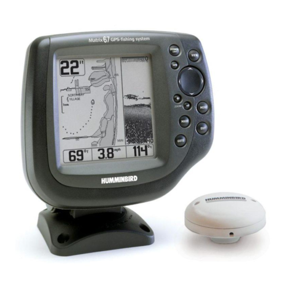
- Page 1 Matrix 67 GPS Trackplotter Matrix 67 GPS Trackplotter Operations Manual Operations Manual 531296-1_A...
-
Page 2: Thank You
Humminbird® is designed for trouble-free use in even the harshest marine environment. In the unlikely event that your Humminbird® does require repairs, we offer an exclusive Service Policy - free of charge during the first year after purchase, and available at a reasonable rate after the one-year period. -
Page 3: Table Of Contents
Table of Contents How Sonar Works DualBeam PLUS™ Sonar ... 1 QuadraBeam™ Sonar (With Optional-Purchase QuadraBeam™ Transducer) ... 1 WideSide Sonar (With Optional-Purchase WideSide Transducer)... 2 How GPS and Cartography Work Multi-Media Card (MMC) ... 3 What’s On the Sonar Display Views Sonar View... - Page 4 Table of Contents ZOOM (+/-) Key ... 27 EXIT Key ... 27 Accessory Bus Powering Up the Unit The Menu System Start-Up Options Menu Normal Operation ... 31 Simulator ... 31 System Status ... 32 PC Connect (with PC Connect Cable Only)... 33 Sonar X-Press™...
- Page 5 Table of Contents Noise Filter (Advanced) ... 50 Max Depth (Advanced) ... 50 Water Type (Advanced) ... 51 Transducer Select ... 51 Navigation Menu Tab Tracks ... 53 Waypoints ... 54 Routes... 55 View Orientation ... 55 Chart Detail Level... 56 Map Borders ...
- Page 6 NOTE: Entries in this Table of Contents which list (with PC Connect Cable Only) or (with Optional- Purchase QuadraBeam /WideSide Transducer) or (with Temp/Speed Only) require the purchase of separate accessories. You can visit our website at www.humminbird.com to order these accessories online or contact our Customer Resource Center at 1-334-687-0503.
-
Page 7: How Sonar Works
It is unlikely that your boat can "outrun" this sonar signal. DualBeam PLUS™ Sonar Your Matrix 67 Fishing System is shipped with a 200/83 kHz DualBeam PLUS sonar system with a wide (60°) area of coverage. DualBeam PLUS sonar returns can be blended together, viewed separately or compared side-by-side. -
Page 8: Wideside Sonar (With Optional-Purchase Wideside Transducer)
WideSide Sonar (with Optional-Purchase WideSide Transducer) Your Matrix 67 Fishing System also supports WideSide sonar with the purchase of an additional WideSide transducer. The WideSide transducer is a specialized "side-looking" transducer that is extremely useful for bank fishing or looking for bait fish in open water. The WideSide transducer uses three different sonar elements that transmit signals to the left, right and straight down from your boat. -
Page 9: Multi-Media Card (Mmc)
Your Matrix Fishing System supports Navionics® Gold Chart marine cartography and Navionics® HotMaps 2004 Gold for inland fishing. NOTE: Your Matrix Fishing System does not support Navionics® Classic Charts, only Navionics® Gold Charts and Navionics® HotMaps 2004 Gold Charts. Your unit also comes with a built-in World map with a more detailed map of North America (Domestic models) or a more detailed map of Europe and Southeast Asia, including Australia and New Zealand (International models). -
Page 10: What's On The Sonar Display
What’s On the Sonar Display The Matrix Fishing System can display a variety of useful information about the area under and adjacent Depth - water depth; can be set to alarm when the water becomes too shallow. Speed - if a Temp/Speed accessory or GPS Receiver is attached, the Matrix Fishing System can display the speed of the boat, and can keep a Triplog of nautical or statute miles traveled. - Page 11 to your boat, including the following items: positioned in the Sonar View to provide depth of a display and the depth of the bottom directly below the cursor. In addition, the Latitude and Longitude of travel to the cursor position and the bearing to the cursor position. A waypoint can be marked at the to the Matrix Fishing System.
-
Page 12: Views
NOTE: Side Beam View and WideSide View require the purchase of the QuadraBeam for the Side Beam View and the WideSide transducer for the WideSide View. You can visit our website at www.humminbird.com to order these accessories online or contact our Customer Resource Center at 1-334-687-0503. -
Page 13: Sonar View
Sonar View Sonar View presents a historical log of sonar returns. Depth is always displayed. Readouts for temperature and speed are automatically displayed if the appropriate accessory is connected. The most recent sonar returns are charted on the right side of the window; as new information is received, the older information is moved across the display to the left. -
Page 14: Understanding Sonar History
Understanding Sonar History It is important to understand the significance of the Matrix Fishing System display. The display does NOT show a literal 3-dimensional representation of what is under the water. Each vertical band of data received by the control head and plotted on the display represents something that was detected by a sonar return at a particular time. -
Page 15: Bottom Presentation
Bottom Presentation As the boat moves, the unit charts the changes in depth on the display to create a profile of the Bottom Contour. The type of bottom can be determined from the return charted on the display. A Hard Bottom such as compacted sediment or flat rock appears as a thinner line across the display. - Page 16 Inverse is a method where weak returns are shown with dark pixels and strong returns with lighter pixels. This has the benefit of ensuring that weak signals will be clearly visible on the display. Structure ID® represents weak returns as light pixels and strong returns as dark pixels.
-
Page 17: Sonar Zoom View
Sonar Zoom View Sonar Zoom View increases the displayed resolution to separate sonar returns that are very close together, such as those caused by fish suspended close to the bottom or within structure. In Zoom View, the display is split to show a narrow slice of the full range view on the right and the zoomed view on the left. -
Page 18: 200/83 Khz Split Sonar View
200/83 kHz Split Sonar View Split Sonar View displays sonar returns from the 83 kHz wide beam on the left side of the screen and displays sonar returns from the 200 kHz narrow beam on the right side of the screen. Depth is always displayed in the upper left hand corner. -
Page 19: Side Beam View
Side Beam View Side Beam View is only available if you have connected a QuadraBeam when Transducer Select is set to QuadraBeam™ (see Sonar Menu Tab: Transducer Select). The QuadraBeam™ transducer requires a separate purchase. This view shows sonar information from both the left and right 90°... -
Page 20: Wideside View
WideSide View WideSide View is only available if you have connected a WideSide transducer accessory and when Transducer Select is set to WideSide (see Sonar Menu Tab: Transducer Select). The WideSide transducer requires a separate purchase. The WideSide View displays information from the 455 kHz SideView transducer. -
Page 21: Bird's Eye View
Bird’s Eye View Bird's Eye View - This view shows a 3-D, perspective view of the track and the chart’s land contour from a point above and behind the boat (the eye point). As the boat turns, the eye point moves to follow the boat. When you press the 4-WAY Cursor key in the Bird’s Eye View, the position of the eye point will shift. -
Page 22: Chart View
Chart View Chart View - This view shows cartography from the built-in UniMap or an optional MMC map for the area surrounding your current position. The current track (also known as the position history or breadcrumb trail) showing where the boat has been, along with saved tracks, waypoints, and the current route (when navigating), are overlaid on the chart. -
Page 23: Combo View
Combo View Combo View - This view is displayed as a split screen, with Chart View on the left and Sonar View on the right side of the screen. The width of the sonar window can be changed. Depth Map Scale Water Surface Temperature View Orientation... - Page 24 Chart View with Cursor Present Overzoom mode whereby the last available chart data is amplified to reflect the scale selected. If you zoom in so far that no cartography is available, a lat/long grid will be drawn instead. Chart Info: Use the INFO key to get detailed information about the chart. If the cursor is active, you will see information about the chart objects located near the cursor.
-
Page 25: Introduction To Navigation
Introduction to Navigation Use the Matrix Fishing System to establish waypoints at areas of interest and to navigate to those waypoints via a saveable route (representing the shortest intended distance between waypoints). You can also view and save tracks, which represent the actual path of the boat. Waypoints, Routes and Tracks Waypoints are stored positions that allow you to mark areas of interest or navigation points. -
Page 26: Save, Edit Or Delete A Waypoint
Save, Edit, or Delete a Waypoint Save your current position as a waypoint: On any view, press the MARK key to save the current position of the boat as a waypoint. Save the cursor position as a waypoint: On the Chart or Combo view, use the Cursor key to designate the position you want to save as a waypoint. -
Page 27: Navigate To A Waypoint Or Position
Delete a waypoint: From the Waypoints submenu, select Delete and press the RIGHT Cursor key to display a list of waypoints. Select the waypoint you want to delete, then press the RIGHT Cursor key. You will be asked to confirm deletion before the waypoint is actually deleted. Navigate to a Waypoint or Position Navigate to the cursor position: From the Chart or Combo view, use the Cursor key to select a position or waypoint to which you want to navigate. -
Page 28: Add A Waypoint Target Or Trolling Grid
Waypoint Target Chart View with Target Waypoint Trolling Grid Chart View with Grid NOTE: Only one waypoint can have either a target or a grid at one time. If you apply a target or a grid to a new waypoint, the original waypoint will lose its target or grid. NOTE: The spacing of the rings on the waypoint target and the spacing of the grid lines on the trolling grid is the same as the length of the scale bar on the left edge of the display. -
Page 29: Save, Edit Or Delete A Route
Save, Edit or Delete a Route Save the current route: While you are navigating, the current route can be saved. From the Navigation X-Press menu, select Save Current Route and press the RIGHT Cursor key. Navigation will continue. Display the Routes submenu: From any view, press the MENU key twice to display the Main Menu System, then use the RIGHT Cursor key to select the Navigation tab. -
Page 30: Save Or Clear A Current Track
Save or Clear a Current Track Save the current track: From the Navigation X-Press RIGHT Cursor key. The track will remain on the display, but will change from black to gray. To remove the track completely from the display, see Edit, Delete or Hide Saved Tracks. NOTE: When you save a track, a name is automatically assigned. -
Page 31: Key Functions
Key Functions Your Matrix Fishing System user interface consists of a set of easy-to-use keys that work with various on-screen views and menus to give you flexibility and control over your fishing experience. POWER/LIGHT Key The POWER/LIGHT key is used to turn the Matrix Fishing System on and off, and also to adjust the backlight and contrast of the display. -
Page 32: Menu Key
MENU Key The MENU key is used to access the menu system. Start-Up Options Menu - Press the MENU key during the power up sequence to view the Start-Up Options menu. X-Press Menu - Press the MENU key once for the X-Press access frequently-used settings without having to navigate through the whole menu system. -
Page 33: Goto Key
GOTO Key If the Cursor is active, pressing the GOTO key while in any view creates a waypoint and starts navigation towards that waypoint. If the Cursor is not active, pressing the GOTO key displays the list of waypoints, so that you can select the waypoint towards which you want to navigate. -
Page 34: Accessory Bus
NOTE: Accessories to enable WeatherSense purchases. You can visit our website at www.humminbird.com or contact our Customer Resource Center at 1-334-687-0503 for additional details. Matrix 67 Title Screen Accessory Bus Use the Accessory Bus to expand the functionality of your Matrix Fishing System. -
Page 35: The Menu System
The Menu System The menu system is divided into easy-to-use menu modules. The main components of the menu system are: Start-Up Options Menu - Press the MENU key during the power up sequence to view the Start-Up Options menu. X-Press are changed frequently without having to navigate through the whole menu system. - Page 36 User Mode (Normal or Advanced) - An Advanced Mode is provided for users who desire the highest level of control over the Matrix Fishing System and Normal Mode for users who desire greater simplicity and fewer menu choices. Additional Advanced menu choices will be displayed throughout the menu system when you navigate to specific menus while in Advanced Mode.
-
Page 37: Start-Up Options Menu
Start-Up Options Menu See the following paragraphs for more information about each of these choices. Normal Operation Use Normal operation for on the water operation with a transducer connected. In addition, your Matrix Fishing System uses advanced transducer detection methods to determine if a transducer is connected. If a functioning transducer is connected, Normal operation will be selected automatically at power up and your Matrix Fishing System can be used on the water. -
Page 38: System Status
System Status Use System Status to view system connections and to conduct a unit self-test. Exit System Status by powering your Matrix Fishing System off. The following screens are displayed in turn when you press the VIEW button when using System Status: •... -
Page 39: Pc Connect (With Pc Connect Cable Only)
Cable accessory. NOTE: The PC Connect Cable requires a separate purchase. For more information visit our website at www.humminbird.com or contact our Customer Resource Center at 1-334-687-0503. Exit PC Connect mode by powering the Matrix Fishing System off. GPS Diagnostic View... -
Page 40: Sonar X-Press Menu (Sonar Views Only)
WideSide view. NOTE: The WideSide View requires the purchase of the WideSide transducer. You can visit our website at www.humminbird.com to order this accessory online or contact our Customer Resource Center at 1-334-687-0503. To adjust the WideSide View: 1. -
Page 41: Sensitivity
Increasing the sensitivity shows more sonar returns from small baitfish and suspended debris in the water; however, the display may become too cluttered. When operating in very clear water or greater depths, increased sensitivity shows weaker returns that may be of interest. Decreasing the sensitivity eliminates the clutter from the display that is sometimes present in murky or muddy water. -
Page 42: Upper Range (Advanced: Sonar, Split Sonar And Big Digits Views Only)
Upper Range sets the shallowest depth range that will be displayed on the Sonar, Split Sonar and Big Digits Views. The Upper Range menu choice is available when User Mode is set to Advanced (see Setup Menu Tab: User Mode) and can only be accessed from the Sonar, Split Sonar and Big Digits Views. Upper Range is often used with Lower Range. -
Page 43: Lower Range
Automatic is the default setting. When in automatic mode, the lower range will be adjusted by the unit to follow the bottom. Selecting a specific setting locks the depth range into Manual mode. Use both Upper and Lower Range together to view a specific depth range manually when looking for fish or bottom structure. -
Page 44: Side Beam Range (Wideside Transducer: Wideside View Only)
Transducer Select) and can only be accessed from the WideSide view. NOTE: The Side Beam Range requires the purchase of the WideSide transducer. You can visit our website at www.humminbird.com to order this accessory online or contact our Customer Resource Center at 1-334-687-0503. -
Page 45: Bottom View
structure on the display. Inverse represents weak returns as dark pixels and strong returns as lighter pixels. This has the benefit of ensuring that weak signals will be clearly visible on the display. Structure ID® represents weak returns as light pixels and strong returns as dark pixels. This has the benefit of ensuring that strong returns will be clearly visible on the display. -
Page 46: Navigation X-Press™ Menu (Navigation Views Only)
Navigation X-Press Menu To Save Current Track: 1. Highlight Save Current Track on the Navigation X-Press 2. Use the RIGHT 4-WAY Cursor Control key to initiate saving the current track. 3. The Confirm dialog box will appear. To save the current track, press the RIGHT Cursor key once more. -
Page 47: Save Current Route (Only When Navigating)
Save Current Route allows you to save the current route being displayed. This menu choice will only appear when you are currently navigating a route. To Save Current Route: 1. Highlight Save Current Route on the Navigation X-Press 2. Use the RIGHT 4-WAY Cursor Control key to initiate saving the current route. 3. -
Page 48: Remove Target (Only If Target Is Active)
Remove Target removes the waypoint target from the display. This menu choice will only appear when a target has already been applied to a waypoint. To Remove a Target: 1. Highlight Remove Target on the Navigation X-Press 2. Use the RIGHT 4-WAY Cursor Control key to remove the target. Remove Grid removes the waypoint grid from the display. -
Page 49: Sonar Menu Tab
Sonar Menu Tab Press the MENU key twice to access the Main Menu System and then press the RIGHT Cursor key to select the Sonar tab. NOTE: Menu choices will vary depending on system settings such as whether the unit is set for Advanced User mode or what transducer is currently selected. -
Page 50: Beam Select
When set to 200/83 kHz, the returns from both beams are blended by starting with the 83 kHz wide beam return, dimming it, and then overlaying it with the 200 kHz narrow beam return. The darker 200 kHz narrow beam sonar returns will stand out from the paler 83 kHz narrow beam sonar returns. The Split Sonar View continues to display the sonar returns from each beam in their respective windows. -
Page 51: Fish Id+ Tm
returns, and will display a Fish Symbol when very selective requirements are met. When a fish is detected, a fish icon and its depth are displayed above the return that has been classified as being a fish. Three different fish size icons represent the intensity of the sonar return, and provide an indicator of relative fish size. -
Page 52: Fish Sensitivity
algorithms. Selecting a higher setting allows weaker returns to be displayed as fish. This is useful for identifying smaller fish species or baitfish. Selecting a lower setting displays fewer fish from weak sonar returns. This is helpful when seeking larger species of fish. Fish Sensitivity is used in conjunction with Fish ID+ . -
Page 53: 455 Khz Balance
Select) and User Mode is set to Advanced (see Setup Menu Tab: User Mode). NOTE: The 455kHz Balance requires the purchase of the QuadraBeam website at www.humminbird.com to order this accessory online or contact our Customer Resource Center at 1-334-687-0503. -
Page 54: Depth Lines (Advanced)
Depth Lines divide the display into four equal sections that are separated by three horizontal depth lines. The depth of each line is displayed along the depth scale. You can either turn Depth Lines On or Off. The Depth Lines menu choice is available when User Mode is set to Advanced (see Setup Menu Tab: User Mode). -
Page 55: Surface Clutter (Advanced)
Surface Clutter adjusts the filter that removes surface clutter noise caused by algae and aeration. The lower the setting, the less surface clutter will be displayed. The Surface Clutter menu choice is available when User Mode is set to Advanced (see Setup Menu Tab: User Mode). To change the Surface Clutter setting: 1. -
Page 56: Noise Filter (Advanced)
Noise Filter adjusts the sonar Noise Filter to limit interference on the display from sources such as your boat engine, turbulence, or other sonar devices. The Noise Filter menu choice is available when User Mode is set to Advanced (see Setup Menu Tab: User Mode). NOTE: The Off setting removes all filtering;... -
Page 57: Water Type (Advanced)
Water Type configures your unit for operation in fresh or salt water. The Water Type menu choice is available when User Mode is set to Advanced (see Setup Menu Tab: User Mode). NOTE: In salt water, what would be considered a large fish might be 2 to 10 times bigger than a large fish in fresh water (depending on the type of fish you are seeking). -
Page 58: Navigation Menu Tab
Navigation Menu Tab Press the MENU key twice to access the Main Menu System, then press the RIGHT cursor key to select the Navigation tab. NOTE: Menu choices will vary depending on system settings. -
Page 59: Tracks
To view the Tracks Submenu: 1. Highlight Tracks on the Navigation main menu. 2. Use the RIGHT 4-WAY Cursor Control keys to view the Tracks submenu. Tracks Submenu The Tracks Submenu contains the following menu choices: Edit allows you to select a previously-saved track and edit its name. Delete allows you to delete a track from a list of previously-saved tracks. -
Page 60: Waypoints
To view the Waypoints Submenu: 1. Highlight Waypoints on the Navigation main menu. 2. Use the RIGHT 4-WAY Cursor Control keys to view the Waypoints submenu. Waypoints Submenu The Waypoints Submenu contains the following menu choices: Create allows you to create a new waypoint and edit it immediately. The current boat position will be used as the default, but you can set the coordinates to any valid position. -
Page 61: Routes
To view the Routes Submenu: 1. Highlight Routes on the Navigation main menu. 2. Use the RIGHT 4-WAY Cursor Control keys to view the Routes submenu. Routes Submenu The Routes Submenu contains the following menu choices: Create allows you to create a new, empty route and add waypoints to it immediately. Edit allows you to select a previously-saved route and edit its name and the waypoints on it. -
Page 62: Chart Detail Level
want displayed on the Navigation Views. Basic shows land areas, ports, obstructions and restricted areas. Navigation shows navaids, landmarks, ferryways and navigation routes in addition to the Basic information. Underwater shows depth contours, fishing areas, underwater wrecks, tides and currents in addition to the Basic and Navigation information. All shows roads, buildings, railways, and other notations in addition to the Basic, Navigation and Underwater information. -
Page 63: Lat-Lon Grid
To change the Lat/Lon Grid setting: 1. Highlight Lat/Lon Grid on the Navigation main menu. 2. Use the LEFT or RIGHT 4-WAY Cursor Control keys to change the Lat/Lon Grid setting. (Hidden, Visible, Default=Hidden) To change the Spot Soundings setting: 1. -
Page 64: Trackpoint Interval
trackpoints. The current track can only contain up to 2000 trackpoints, so longer time periods cause the track to extend back further in time, but will be less detailed. NOTE: Trackpoint Interval works in conjunction with Track Min Distance. Both conditions must be met before a trackpoint is added to the current track. -
Page 65: Map Datum (Advanced)
Map Datum allows you to change the map coordinate system used by the Matrix Fishing System to match those of a paper map. To change the Map Datum setting: 1. Make sure you are in Advanced User Mode, then highlight Map Datum on the Navigation main menu. -
Page 66: Clear Map Offset (Advanced)
Clear Map Offset allows you to clear the Map Offset. Clear Map Offset is only accessible if a Map Offset is currently active. To Clear Map Offset: 1. Make sure you are in Advanced User Mode, then highlight Clear Map Offset on the Navigation main menu. -
Page 67: Alarms Menu Tab
Alarms Menu Tab From any view, press the MENU key twice to access the Main Menu System. The Alarms tab will be the default selection. NOTE: When an alarm is triggered, you can silence it by pressing any key. The alarm will be silenced, and will not be triggered again until a new instance of the alarm condition is detected. -
Page 68: Depth Alarm
To change the Depth Alarm setting: 1. Highlight Depth Alarm on the Alarms main menu. 2. Use the LEFT or RIGHT 4-WAY Cursor Control keys to change the Depth Alarm setting. (OFF, 1 to 100 feet, or 0.5 to 30 meters [International Models Only], Default = OFF) For example, if you've set the Fish ID Alarm to sound for Large fish only, the Fish ID alarm will sound when a large-sized fish is detected. -
Page 69: Low Battery Alarm
or less than the menu setting. The battery alarm will only sound for the battery that is connected to the Matrix Fishing System. The Low Battery Alarm should be set to warn you when the battery voltage drops below the safety margin that you have determined. For instance, if you are running a trolling motor (battery operated), you would want to set the Low Battery Alarm to sound before the battery voltage drops too low for it to be used to start your main, gasoline-powered engine. -
Page 70: Arrival Alarm
distance to the destination waypoint, or has entered the Arrival Alarm Circle, based on the menu setting when navigating. Arrival Alarm allows you to set how close the boat must be to the destination waypoint before the Arrival Alarm will sound. To change the Arrival Alarm setting: 1. -
Page 71: Setup Menu Tab
Setup Menu Tab From any view, press the MENU key twice to access the tabbed Main Menu System, then press the RIGHT cursor key until the Setup tab is selected. NOTE: Menu choices will vary depending on system settings such as whether the unit is set for Advanced User mode and what accessories are attached to the unit. -
Page 72: Units - Depth
To change the Units - Depth setting: 1. Highlight Units - Depth on the Setup menu. 2. Use the LEFT or RIGHT 4-WAY Cursor Control keys to change the Units - Depth setting. (Meters [International Models Only], Feet, Fathoms; Default is Meters for International models, and Feet for Domestic models) Units - Temp selects the units of measure for all temperature-related readouts. -
Page 73: Units - Speed
To change the Units - Speed setting: 1. Highlight Units - Speed on the Setup menu. 2. Use the LEFT or RIGHT 4-WAY Cursor Control keys to change the Units - Speed setting. (kph [International Models Only], mph, kts, Default = kph for International models and mph for Domestic models) When set to Normal (default setting,) only the basic menu options are shown. -
Page 74: Triplog Reset
following information: timer for elapsed time, distance traveled since last reset, and average speed. NOTE: See Setup Menu Tab: Select Readouts (Advanced) to find out how to display Triplog information on the screen. To Reset Triplog: 1. Highlight Reset Triplog on the Setup menu. 2. -
Page 75: Select Views (Advanced)
Select Views To Select Views: 1. Make sure you are in Advanced User Mode, then highlight Select Views on the Setup menu. 2. Use the RIGHT 4-WAY Cursor Control key to initiate this procedure. 3. The Select Views submenu will appear, showing a list of all Views that can be hidden or made visible. -
Page 76: Select Readouts (Advanced, Sonar View Only)
Select Readouts Default Sonar View To Select Readouts: 1. Make sure you are in Advanced User Mode, then highlight Select Readouts on the Setup main menu. 2. Use the RIGHT 4-WAY Cursor Control key to initiate this procedure. 3. The Select Readouts submenu will appear, showing a list of all Readouts. Use the UP or DOWN Cursor keys to select a particular Readout position, then use the RIGHT or LEFT Cursor keys to change what will be displayed at that position. -
Page 77: Depth Offset (Advanced)
Depth Offset will adjust the digital depth readout to indicate depth from the waterline or boat's keel. Enter a positive vertical measurement from the transducer to the waterline to read the depth from the waterline. Enter a negative vertical measurement from the transducer to keel to read the depth from the keel. -
Page 78: Local Time Zone (Advanced)
Local Time Zone selects your time zone in reference to the time reported by the GPS receiver when Time+Date is selected as a Digital Readout on the Sonar View (see Select Readouts). This menu choice is available only when in Advanced User Mode (see Setup Menu Tab: User Mode.) To change the Local Time Zone: 1. -
Page 79: Time Format (Advanced, International Only)
Time Format changes the time format used by the unit This menu choice is available only when in Advanced User Mode (see Setup Menu Tab: User Mode.) International Models Only. Time Format selects a 12 hour or 24 hour format for the time of day displayed when Time + Date is selected as a Digital Readout on the Sonar View (see Select Readouts). -
Page 80: Nmea Output (Advanced)
NMEA Output turns the NMEA output on or off. This menu choice is available only when in Advanced User Mode (see Setup Menu Tab: User Mode.) The following NMEA sentences are output: DPT- Depth MTW - Water Temperature GLL - Lat/Lon Position GGA - GPS Fix Data RMC - Recommended Minimum Specific GNSS Data VTG - Course Over Ground and Ground Speed... -
Page 81: Accessories Menu Tab
See the Operations Manual that comes with your accessory for detailed information. Accessories Menu Tab (no accessories attached) NOTE: Accessories to enable WeatherSense purchases. You can visit our website at www.humminbird.com or contact our Customer Resource Center at 1-334-687-0503 for additional details. Accessories Menu Tab (with accessories attached) -
Page 82: Troubleshooting
Troubleshooting Before contacting the Humminbird Customer Resource Center, please read the following section. Taking the time to review these troubleshooting guidelines may allow you to solve a performance problem yourself, and therefore avoid sending your unit back for repair. Fishing System Doesn’t Power Up If your Matrix Fishing System doesn’t power up, use the Installation Guide that also comes with it for... -
Page 83: Display Problems
Display Problems There are several main conditions or sources of possible interference that may cause problems with the quality of the information displayed on the control head. Look in the following table for some symptoms of display problems and possible solutions: Problem The control head loses power at high speeds. -
Page 84: Finding The Cause Of Noise
Finding the Cause of Noise Electrical noise usually affects the display with many black dots at high speeds, and high sensitivity readings. One or more of the following sources can cause noise or interference: Possible Source of Noise Isolation Other electronic devices The boat’s engine Cavitation from the boat’s propeller... -
Page 85: Matrix Fishing System Accessories
MSWindows-compatible HumminbirdPC™ software downloaded from our website to your PC in order to communicate with the Matrix Fishing System. Be sure to check out our website www.humminbird.com for additional new and exciting accessories to grow your Matrix Fishing System! NOTE: Each accessory requires a separate purchase. -
Page 86: Specifications
Specifications Depth Capability ... 1500 ft (500 m) Power Output ... 500 Watts (RMS), 4000 Watts (Peak to Peak) Operating Frequency... 200 kHz and 83 kHz DualBeam PLUS Area of Coverage ... 60° @ -10 dB in 83 kHz 20° @ -10 dB in 200 kHz Target Separation ... -
Page 87: Notes
Notes... -
Page 88: Contact Humminbird
Contact Humminbird Contact the Humminbird Customer Resource Center in any of the following ways: By Telephone (Monday - Friday 8:00 a.m. to 4:30 p.m. Central Standard Time): 334-687-0503 By e-mail (typically we respond to your e-mail within three business days): custserv@techsonic.com...