Table of Contents
Advertisement
Quick Links
Advertisement
Table of Contents

Related Manuals for Extron electronics XTP T VGA


Summary of Contents for Extron electronics XTP T VGA
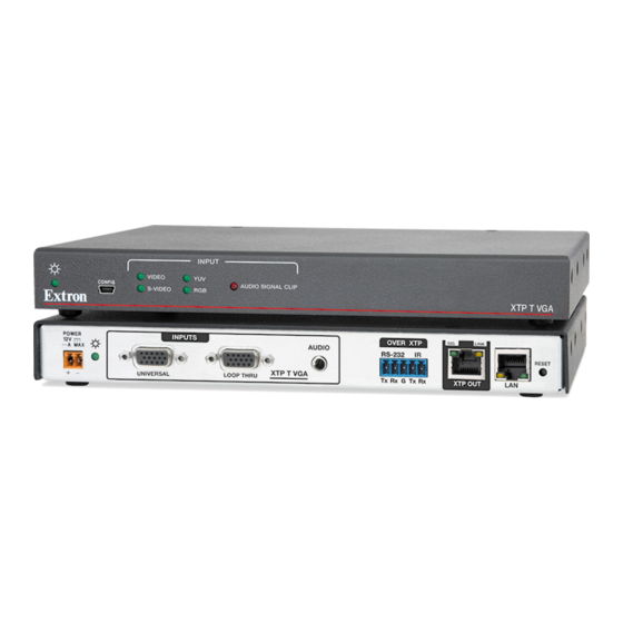
- Page 1 User Guide XTP Extender XTP T VGA XTP VGA Transmitter 68-2091-01 Rev. A 01 14...
-
Page 2: Safety Instructions
Safety Instructions Safety Instructions • English Инструкция по технике безопасности • Русский WARNING: This symbol, , when used on the product, is intended to ПРЕДУПРЕЖДЕНИЕ: Данный символ, , если указан alert the user of the presence of uninsulated dangerous voltage within the на... - Page 3 Compliance Guide” on the Extron website. Copyright © 2014 Extron Electronics. All rights reserved. Trademarks All trademarks mentioned in this guide are the properties of their respective owners. The following registered trademarks , registered service marks...
- Page 4 Conventions Used in this Guide Notifications The following notifications are used in this guide: A warning indicates a situation that has the potential to result in death or WARNING: severe injury. ATTENTION: Attention indicates a situation that may damage or destroy the product or associated equipment.
-
Page 5: Table Of Contents
........... 1 ..16 About this Guide ..........1 Installing the XTP System Configuration Software ............16 About the XTP T VGA ......... 1 Using the XTP System Configuration Key Features ............2 Software ............17 Connections ..........17 Installation and Operation ...... - Page 6 XTP T VGA • Contents...
-
Page 7: Introduction
This guide contains installation, operation, and control procedures; and reference information for the XTP T VGA Universal XTP Transmitter. In this guide, the terms “XTP T VGA” and “transmitter” are used interchangeably to refer to the XTP T VGA Universal XTP Transmitter. -
Page 8: Key Features
Ethernet pass-through port to reduce the amount of independent network drops required within a system. Remote power capability — To simplify integration, the XTP T VGA can be powered by an XTP CrossPoint matrix switcher or XTP Power Injectors. -
Page 9: Installation And Operation
Rear Panel Connectors Audio Plugs.eps • Making Connections • Operation The XTP T VGA can be mounted in a rack, under a desk, or on a tabletop (see Mounting on page 28 for more mounting details). Tip (+) Rear Panel Connectors LINK... - Page 10 2-pole captive screw connector (see Power Connection on page 8). The Power LED lights to indicate the device is receiving power. NOTE: The XTP T VGA can be powered remotely (see Remote power on page 9). XTP T VGA • Installation and Operation...
-
Page 11: Making Connections
L return Video return return Blue return Blue return Blue return B-Y return C return Ground Ground Ground connection connection connection EDID/DDC EDID/DDC EDID/DDC H sync C sync V sync EDID/DDC EDID/DDC EDID/DDC XTP T VGA • Installation and Operation... -
Page 12: Tp Cable Termination And Recommendations
Figure 4. TP Cable Termination Connector Supported cables The XTP T VGA is compatible with CAT 5e, 6, 6a, and 7 shielded twisted pair (F/UTP, SF/UTP, and S/FTP) and unshielded twisted pair (U/UTP) cable. ATTENTION: • Do not use Extron UTP23SF-4 Enhanced Skew-Free AV UTP cable or STP201 cable to link the XTP products. -
Page 13: Rs-232 And Ir Over Xtp Communication
The length of exposed wires is critical. • The ideal length is 3/16 inch (5 mm). • Longer bare wires can short together • Shorter wires are not as secure in the connectors and could be pulled out. XTP T VGA • Installation and Operation... -
Page 14: Power Connection
Output Cord Figure 6. Power Wiring The XTP T VGA can be connected to a local power supply. Electric shock hazard. The two power cord wires must be kept separate WARNING: while the power supply is plugged in. Remove power before wiring. - Page 15 Remote power The XTP T VGA can be powered remotely through an XTP Power Injector or through an XTP matrix switcher. ATTENTION: XTP remote power is intended for indoor use only. No part of the network that uses XTP remote power should be routed outdoors.
-
Page 16: Operation
-3 dBFS or above. The light remains lit for 200 ms after the audio input signal drops below -3 dBFS. EDID To manage EDID on the XTP T VGA, use the XTP System Configuration Software (see System Configuration Software on page 16) . The XTP T VGA can record and save EDID in a user memory location, select a pre-defined EDID, or use EDID from a display connected to a receiver. -
Page 17: Sis Configuration And Control
Use a computer running the HyperTerminal or Extron DataViewer utility, or a control system to enable serial control of the transmitter. To connect directly to an XTP T VGA, connect the computer to the XTP T VGA through the front panel USB Config port... -
Page 18: Using The Command And Response Table For Sis Commands
ASCII to Hex Conversion Table Space • Figure 9. ASCII to Hexadecimal Conversion Symbol Definitions = Carriage return and line feed = Carriage return with no line feed = Space • = Escape key or W XTP T VGA • SIS Configuration and Control... -
Page 19: Command And Response Tables For Sis Commands
0-24 = Audio attenuation -18-0 = Audio level -18-+24 = default) X& = Black signal resolution = 720p @ 50 Hz = 720p @ 60 Hz (default) = 1080p @ 60 Hz XTP T VGA • SIS Configuration and Control... -
Page 20: Picture Adjustment Commands
Increase the pixel phase value. +PHAS Phas Decrement value Decrease the pixel phase value. -PHAS Phas View pixel phase Show the pixel phase value. PHAS Phas NOTE: = Picture adjustment = default) 0-255 XTP T VGA • SIS Configuration and Control... -
Page 21: Preset Commands
= Test pattern = off (default) = 720p @ 50 Hz = 720p @ 60 Hz = 1080p @ 60 Hz = Input signal presence = no input detected = input detected XTP T VGA • SIS Configuration and Control... -
Page 22: Xtp System Configuration Software
XTP System Configuration Software The XTP T VGA can be configured and controlled using Extron Simple Instruction Set (SIS) commands (see SIS Configuration and Control on page 11) or the XTP System Configuration Software. This section contains installation and configuration procedures for the XTP System Configuration Software for configuring and controlling the XTP T VGA. -
Page 23: Using The Xtp System Configuration Software
Using the XTP System Configuration Software The XTP T VGA can be controlled directly from the front panel config port or remotely from an XTP matrix switcher. Connections When opening the XTP System Configuration Software, the Connections screen opens first. -
Page 24: Top Menu
To access this menu, click the Tools menu. Tools Figure 13. Tools Menu NOTE: The options are not Backup and Restore Software Preference available when directly connected to the XTP T VGA. XTP T VGA • XTP System Configuration Software... -
Page 25: Update Firmware
Select file from computer connected host device. Select the desired firmware file and click the button after the firmware finishes Close updating. XTP T VGA • XTP System Configuration Software... - Page 26 This option opens the XTP System Configuration Software help file in a Web browser. From the menu, select Help Help Extron Website This option opens the Extron website in a Web browser. From the menu, select Help Extron Website XTP T VGA • XTP System Configuration Software...
-
Page 27: Device Settings
Figure 18. Transmitter Device Settings Screen Input/Output tab Click the tab to open the Input/Output screen. It contains input Input/Output configuration, image settings, preset management, and output configuration options. Figure 19. Input/Output Tab XTP T VGA • XTP System Configuration Software... - Page 28 Auto Memory Memory recalls input and image settings for signals that have previously been applied. When it is disabled, the XTP T VGA treats every newly applied input as a new source. Image Settings panel To optimize the input signal: Figure 20.
- Page 29 Figure 24. Output Configuration panel To enable a color bars test pattern: Select the check box. Color Bars Test Pattern From the drop-down list, select the desired resolution and refresh rate. Signal Type XTP T VGA • XTP System Configuration Software...
- Page 30 Signal Type emulate in place of video. Factory reset Click the button to reset the transmitter to factory settings except for Factory Reset firmware. XTP T VGA • XTP System Configuration Software...
- Page 31 Signal type — Displays the current signal type setting (see Input Configuration panel page 22). Current EDID Information section Display the current EDID selected. Audio Information section Analog audio gain — Displays the analog audio gain in dB. XTP T VGA • XTP System Configuration Software...
- Page 32 Select the desired EDID file and click . The EDID appears in the Available EDID Open pane. Assign the EDID from the Available EDID pane to import the EDID setting to the device. XTP T VGA • XTP System Configuration Software...
- Page 33 Hold <Ctrl> and click the desired outputs in the Connected Outputs pane. The Common tab appears, listing the EDID settings common among the selected outputs. Timings Select the desired common EDID setting. The EDID will be shown in the Available EDID pane. XTP T VGA • XTP System Configuration Software...
-
Page 34: Reference Information
Updating Firmware with Firmware Loader Mounting The XTP T VGA can be placed on a tabletop or mounted in a rack or underneath a desk. Tabletop Mounting Attach the provided rubber feet to the bottom four corners of the enclosure. -
Page 35: Updating Firmware With Firmware Loader
Updating Firmware with Firmware Loader To upload and update firmware on the XTP T VGA, download the new firmware to a connected computer and upload the firmware with the Extron Firmware Loader utility. Downloading Extron Firmware Loader Figure 28. Software on the Extron Website On the Extron website, click the tab. -
Page 36: Installing Firmware Loader
The file can be downloaded from the same page as the firmware. Click the link to the right of the desired device. Download If required, enter any required information to start the download. Note where the file is saved. XTP T VGA • Reference Information... -
Page 37: Installing Firmware With Firmware Loader
Firmware Loader main window. Click the button to start the upload process. Begin Close Firmware Loader when the field shows , the Remaining Time 00.00.00 column shows , and the field shows Progress 100% Status completed XTP T VGA • Reference Information... - Page 38 Extron Electronics makes no further warranties either expressed or implied with respect to the product and its quality, performance, merchantability, or fitness for any particular use. In no event will Extron Electronics be liable for direct, indirect, or consequential damages resulting from any defect in this product even if Extron Electronics has been advised of such damage.