Table of Contents
Advertisement
Quick Links
HP 8360 Series Synthesized Sweepers
(Including Options 001, 003, 004, 006, and 008)
User's Handbook
SERIAL NUMBERS
This manual applies directly to any synthesized sweeper with serial
number prefix combinations. You may have to modify this manual
so that it applies directly to your instrument version. Refer to the
"Instrument History" chapter.
HP
HP 83630A
HP
HP
HP
HP Part No. 08380-90070
Microfiche Part No. 08380-90073
Printed in USA
November 1995
Edition 9
Advertisement
Chapters
Table of Contents

Related Manuals for HP HP 8360


Summary of Contents for HP HP 8360
- Page 1 HP 8360 Series Synthesized Sweepers (Including Options 001, 003, 004, 006, and 008) User’s Handbook SERIAL NUMBERS This manual applies directly to any synthesized sweeper with serial number prefix combinations. You may have to modify this manual so that it applies directly to your instrument version. Refer to the “Instrument History”...
- Page 2 Notice Restricted Rights Legend The information contained in this document is subject to change without notice. Hewlett-Packard makes no warranty of any kind with regard to this material, including but not limited to, the implied warranties of merchantability and fitness for a particular purpose. Hewlett-Packard shall not be liable for errors contained herein or for incidental or consequential damages in connection with the furnishing, performance, or use of this material.
- Page 3 Certification Warranty Hewlett-Packard Company certifies that this product met its published specifications at the time of shipment from the factory. Hewlett-Packard further certifies that its calibration measurements are traceable to the United States National Institute of Standards and Technology, to the extent allowed by the Institute’s calibration facility, and to the calibration facilities of other International Standards Organization members.
- Page 4 Assistance Safety Notes WARNING CAUTION Product maintenance agreements and other customer assistance agreements are available for Hewlett-Packard products. For any assistance, contact your nearest Hewlett-Packard Sales and Service Ofice. The following safety notes are used throughout this manual. Familiarize yourself with each of the notes and its meaning before operating this instrument.
- Page 5 General Safety Considerations WARNING No operator serviceable parts inside. Refer servicing to qualified personnel. To prevent electrical shock, do not remove covers. For continued protection against fire hazard replace line fuse only with same type and rating (F 5A/25OV). The use of other fuses or material is prohibited.
- Page 6 CAUTION Note H Before switching on this instrument, make sure that the line voltage selector switch is set to the voltage of the power supply and the correct fuse is installed. Always use the three-prong ac power cord supplied with this instrument.
- Page 7 PREFACE Instruments Covered By This Manual This manual provides user information for the HP 8360 Series Synthesized Sweepers. This manual applies to instruments having a serial number prefix listed on the title page (behind the “Documentation Map” tab). Some changes may have to be made to this manual so that it applies directly to each instrument;...
- Page 8 Tabs divide the major chapters of this manual. The contents of each “Table of Contents.” chapter is listed in the Documentation Map For a pictorial representation of the HP 8360 series documentation, “Documentation Map” Ordering Manual A manual part number is listed on the title page of this manual. You may use it to order extra copies of this manual.
- Page 9 Model HP 8360 Series Synthesized Sweepers Hiermit wird bescheinigt, dass dieses Gerat/System in Ubereinstimmung mit den Bestimmungen von Postverfiigung 1046/84 funkentstijrt ist .
- Page 10 Notice for Germany: Noise Declaration Declaration of Conformity LpA < 70 dB am Arbeitsplatz (operator position) normaler Betrieb (normal position) nach DIN 45635 T. 19 (per IS0 7779)
- Page 11 Microwave Instruments Division 1400 Fountaingrove Parkway Santa Rosa, CA 95403-1799 Synthesized Sweeper HP 8362OA, HP 8362lA, HP 83622A, HP 83623A, HP 83624A, HP 8363OA, HP 8363lA, HP 8364OA, HP 36642A, HP 8365OA, HP 83651A This declaration covers all options of the above products.
- Page 12 Instrument Markings ! A The instruction documentation symbol. The product is marked with this symbol when it is necessary for the user to refer to the instructions in the documentation. The CE mark is a registered trademark of the European Community.
- Page 13 Hewlett-Packard Sales and Service Offices Headquarters California, Northern Hewlett-Packard Co. Hewlett-Packard Co. 19320 Pruneridge Avenue 301 E. Evelyn Cupertino, CA 95014 Mountain View, CA 94041 (800) 752-0900 (415) 694-2000 Colorado Georgia Hewlett-Packard Co. Hewlett-Packard Co. 24 Inverness Place, East 2000 South Park Place Englewood, CO 80112 Atlanta, GA 30339 (303)
-
Page 14: Table Of Contents
How To Use This Chapter ... . Equipment Used In Examples Introducing the HP 8360 Series Synthesized Sweepers Display Area .... - Page 15 Instrument Addresses ... . . HP-IB Instrument Nomenclature ..Listener ....
- Page 16 ....Using the Example Programs Use of the Command Tables ..HP-IB Check, Example Program 1 Program Comments ... .
- Page 17 The INIT Configuration ... The TRIG Configuration Description of Triggering in the HP 8360 Series Synthesizers ....
- Page 18 HP 8360 User’s Handbook hM Type 100%fV ....ANALYZER STATUS REGISTER ..ArrowKeys ....
- Page 19 Global Dwell ....... . . Global Offset HP 8360 User’s Handbook F - l...
- Page 20 HP 8360 User’s Handbook HP-IB Address ....Menu HP-IB ....
- Page 21 Preset Mode User ......M-10 M-10 M-11 M-12 M-12 M-14 M-17 M-19 M-23 M-24 M-24 M-25 M-26 M-26 M-27 M-28 HP 8360 User’s Handbook P-10...
- Page 22 HP 8360 User’s Handbook Printer Adxs ....(PRIOR) ... . Programming Language Analyzr Programming Language CIIL . .
- Page 23 ........HP 8360 User’s Handbook S-64 S-64...
- Page 24 HP 8360 User’s Handbook ZeroFreq ........Wavef ofllt Nenu Zoom .
- Page 25 Option 910 Extra Operating & Service Manuals Option 013 Rack Flange Kit ..Option W30 Two Years Additional Return-To-HP Service ....
- Page 26 ....The HP 8970B Noise Figure Meter ....
- Page 27 Change A ....Index 3-23 3-23 3-23 3-24 3-24 ......HP 8360 User’s Handbook...
- Page 28 O-l. Typical Serial Number Label ..l-l. The HP 83620A Synthesized Sweeper ..1-2. Display ....
- Page 29 Network Analyzer Measurement System 3-l. AC Power Cables Available 3-2. Rear Panel HP-IB Switch ... 3-3. Removing the Side Straps and Feet ..3-4. Chassis Slide Kit ....
- Page 30 D-l. Mnemonics used to Indicate Status ..S-l. HP 8360 SCPI COMMAND SUMMARY ..3-l. Language HP-IB Addresses ..3-2. Factory-Set HP-IB Addresses ..
-
Page 31: Getting Started
GETTING STARTED What Is In This Chapter Note This chapter contains information on how to use the HP 8360 Series Synthesized Sweeper. The information is separated into three sections. Basic For the novice user unfamiliar with the HP 8360 Series Synthesized Sweepers. This section describes the basic features of the synthesizer. -
Page 32: How To Use This Chapter
You can substitute equipment, but be aware that you may get different results than those shown. Equipment Used In Examples Equipment Power Meter Power Sensor Power Splitter Oscilloscope mm-Wave Source Module HP 83556A Power Amplifier Coupler Detector ’ Recommended Model Numbers HP 436A/437B... -
Page 33: Introducing The Hp 8360 Series Synthesized Sweepers
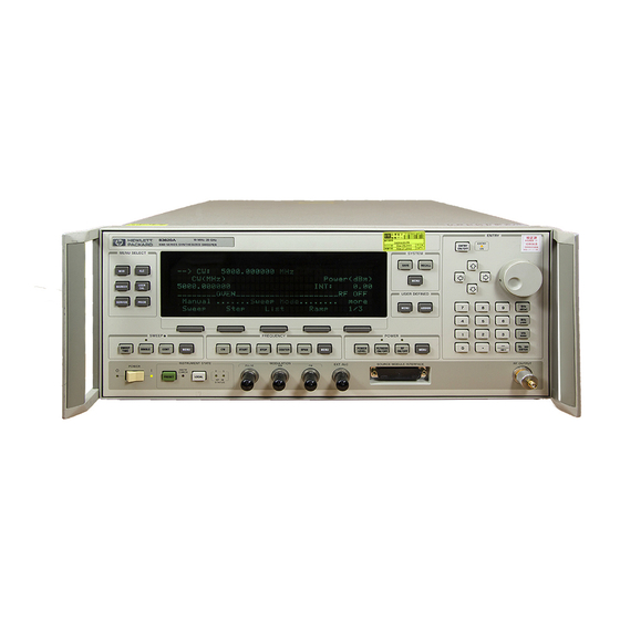
PRESET Figure l-l. The HP 83620A Synthesized Sweeper Getting Started Basic The HP 8360 Series Synthesized Sweepers are high performance, broadband frequency synthesizers. (PRESET) initializes the front panel settings and runs the synthesizer through a brief self-test. In the following examples, unless stated otherwise, begin by pressing (PRESET). -
Page 34: Display Area
Display Area l-4 Getting Started Basic SOFTKEYS Figure l-2. Display Active Entry and Data Display Area: the frequency and power information of the current instrument state. When data entry is expected, the synthesizer uses all or part of this area to record the entries. The active entry arrow (-->) indicates the active entry function and its current value. -
Page 35: Entry Area
Entry Area All function values are changed via the rotary knob and/or keys of the entry area. ENTRY ENTRY ON ON/OFF ENTRY NUMERIC NEGATlVE ENTRY KEYS Figure l-3. Entry Area The following are active only when the synthesizer expects an input. This key lets you turn off or on the active entry E N T R Y O F F... -
Page 36: Cw Operation And Start/Stop Frequency Sweep
CW Operation and Start/Stop Frequency Sweep CW Operation Start/Stop Frequency Sweep 1-6 Getting Started Basic CW operation is one of the major functions of the synthesizer, and is easy to do using front panel keys. In CW operation, the synthesizer produces a single, low-noise, synthesized frequency. - Page 37 dLETT K.ARO INSWMENT STATE SWEEP LED Figure 1-4. CW Operation and Start/Stop Frequency Sweep CW Operation 1. Press Icw). 2. Enter value. 3. Press terminator key. SOURCE MODULE INTERFACE STOP START s t a r t / s t o p Frequency Sweep 1.
-
Page 38: Center Frequency/Span Operation
Center Frequency/Span Operation 1-6 Getting Started Basic Center frequency/span is another way of establishing swept operation. This is just a different way of defining sweep limits. As an example of center frequency/span operation: Press m(7J IGHz). Press ISPAN) (iJ (GHz). The synthesizer is now sweeping from 3.5 to 4.5 GHz (to view these figures, press either (START) or (STOP), then m). - Page 39 SWEEP LED Figure 1-5. Center Frequency and Span Operation Center Frequent y 1. Press (jCENTEji). 2. Enter value. 3. Press terminator key. CENTER SPAN Span Operation 1. Press m. 2. Enter value. 3. Press terminator key. Getting Started Basic l-9...
-
Page 40: Power Level And Sweep Time Operation
Power Level and Sweep Time Operation Power Level Operation Sweep Time Operation l-10 Getting Started Basic The synthesizer can produce leveled power for CW, swept frequency, or power sweep operation. The selected power level can range from -20 dBm (-110 dBm for option 001 synthesizers) to +25 dBm. For practice: Press POWER LEVEL area shows:... - Page 41 . .,WLETT L”pI PACKARO SWEEP SWEEP TIME Figure 1-6. Power Level and Sweep Time Operation Power Level Operation 1. Press CPOWER LEVEL). 2. Enter value. 3. Press IdBo). POWER LEVEL Sweep Time Operation 1. Press &WEEP TtME]. 2. Enter value. 3.
-
Page 42: Continuous, Single, And Manual Sweep Operation
Continuous, Single, and Manual Sweep Operation 1-12 Getting Started Basic Continuous sweep is the operation mode set when the synthesizer is preset. It simply means that when the synthesizer is performing a swept operation, the sweeps will continuously sweep-retrace-sweep- retrace until a different sweep mode is selected. To choose this sweep mode, press (CONT). - Page 43 SWEEP SINGLE CONT Figure 1-7. Continuous, Single, and Manual Sweep Operation Single Sweep 1. Press (SINGLE). SWEEP MENU Continuous Sweep 1. Press c-1. Manual Sweep 1. Press SWEEP (MENU). 2. Press Manual Sweep 3. Use the rotary knob to adjust frequency. Getting Started Basic 1-13...
-
Page 44: Marker Operation
Marker Operation Caution 1-14 Getting Started Basic The synthesizer has five frequency markers that can be used as fixed frequency “landmarks,” or as variable frequency pointers on a CRT display. To view the marker features of the synthesizer on a CRT, connect the synthesizer as shown in Figure 1-8. -
Page 45: Marker Operation
Marker Operation 1. Press @i?GGiZ). Select a marker key ( Ni . . MS ). 3. Enter value. 4. Press terminator key. Marker 1 was chosen because it is selected as the delta marker reference. To change reference markers, select Select M2 as the reference. -
Page 46: Saving And Recalling An Instrument State
Saving and Recalling an Instrument State 1-16 Getting Started Basic The save/recall registers store and access a previously set instrument state. For example, set the synthesizer to sweep from 3 to 15 GHz at a -10 dB power level, with markers 1 and 2 set at 4.5 and 11.2 GHz. Press [START) (7J (GHz). - Page 47 Figure 1-9. Saving and Recalling an Instrument State Save 1. Setup synthesizer as desired. 2. Press [SAVE. 3. Press a number 1 through 8. RECALL Recall 1. Press @EGiIiJ. 2. Press a number 0 through 8. Getting Started Basic l-17...
-
Page 48: Power Sweep And Power Slope Operation
Power Sweep and Power Slope Operation Power Sweep Operation 1-18 Getting Started Basic The power sweep function allows the power output to be swept (positive or negative) when the synthesizer is in the CW frequency mode. The power output of the synthesizer determines the maximum leveled power sweep that can be accomplished. -
Page 49: Power Slope Operation
The synthesizer performs a power sweep beginning at -20 dBm and ending at f5 dBm. The power meter indicates +25 dB. Power Slope Operation This function allows for compensation of high frequency system or cable losses by linearly increasing the power output as the frequency increases. -
Page 50: L-10. Power Sweep And Power Slope Operation
S Y N T H E S I Z E R Figure l-10. Power Sweep and Power Slope Operation Power Sweep 1. Press POWER (jMENU). 2. Select Pouer Saeep . 3. Enter a value. 4. Press terminator key. l-20 Getting Started Basic P O U E R IlETER ‘UT Power Slope... -
Page 51: Getting Started Advanced
Advanced This section of Chapter 1 describes the use of many of the unique features of the HP 8360 Series Synthesized Sweepers. The format used is similar to the one used on the previous pages. When referred to a menu map number, go to the Menu Map tab and unfold the menu map so that you can view it together with the text. - Page 52 1-22 Getting Started Advanced Advanced Keys Under Discussion in This Section (continued) Paragraph Heading Optimizing Synthesizer Performance continued Using Step Sweep Creating and Using a Frequency List Using the Security Features Changing the Preset Parameters For more of these keys has information,each “OPERATING and PROGRAMMING REFERENCE”...
-
Page 53: Externally Leveling The Synthesizer
Externally Leveling the Synthesizer Leveling with Detectors/Couplers /Splitters In externally leveled operations, the output power from the synthesizer is detected by an external sensor. The output of this detector is returned to the leveling circuitry, and the output power is automatically adjusted to keep power constant at the point of detection. - Page 54 Power splitters have a coupling factor of 0 dB. Figure 1-12 shows the input power versus output voltage characteristics for typical HP diode detectors. From the chart, the leveled power at the diode detector input resulting from any external level voltage setting may be determined. The range of power adjustment is approximately -30 dBm to i-18 dBm.
- Page 55 100 mV SQUARE LAW ASYMPTOTE 10 mV 1 mV .l mV Figure 1-12. Typical Diode Detector Response at 25°C DETECTOR INPUT POWER, dBm +20 d6V +lO dBV 0 dBV - 1 0 dBV - 2 0 dBV - 3 0 dBV - 4 0 dBV - 5 0 dBV -60 dBV...
-
Page 56: External Leveling Used With The Optional Step Attenuator
Hint l-26 Getting Started Advanced External Leveling Used With the Optional Step Attenuator Some external leveling applications require low output power from the synthesizer. The synthesizer automatically uncouples the attenuator from the ALC system for all external leveling points. Press Note the display. -
Page 57: Leveling With Power Meters
Leveling with Power Leveling with a power meter is similar to leveling with a diode detector. Figure 1-13 shows the setup for power meter leveling. Meters 1. Set up the equipment as shown. Be sure to set the power meter to 2. -
Page 58: Leveling With Mm-Wave Source Modules
Leveling with MM-wave Millimeter-wave source module leveling is similar to power meter leveling. The following figures illustrate the setups for leveling with a Source Modules mm-wave source module. SYNTHESIZER Figure 1-14. MM-wave Source Module Leveling High power model synthesizers can externally, level mm-wave source modules to maximum specified power without a microwave amplifier. -
Page 59: Mm-Wave Source Module Leveling Using A Microwave Amplifier
RF OUT AORPTER (IF REQUIRED) Figure 1-15. MM-wave Source Module Leveling Using a Microwave Amplifier 1. Set up the equipment as shown. 2. Refer to menu map 1. 3. Select Leveling Point Module. 4. Select Mdl Lev Menu. 5. Select Module Leveling Pt Auto or Front or Rear, depending on where the interface connection is made. -
Page 60: Working With Mixers/Reverse Power Effects
Working with Mixers/Reverse Power Effects Note I-30 Getting Started Advanced Uncoupled operation applies to Option 001 synthesizers only. Uncoupled operation is useful when working with mixers. Figure 1-16 shows a hypothetical setup where the synthesizer is providing a small signal to a mixer. The synthesizer output is -8 dBm, which in Leveling Node Normal results in ATTEN = 0 dB, ALC Level = -8 dBm. -
Page 61: Reverse Power Effects, Coupled Operation With
swrNEsl2ER DETECTOR MEASURES -8 dBm MC LEVEL Figure l-16. Reverse Power Effects, Coupled Operation with -6dBm Output sYNTNEsl2ER WITH OPTlON 001 MC LEVEL - +2 dBm R F L E V E L _ CONTROL ,, Q DETECTOR MEASURES +2 dBm iI 0 M C LmEL Figure 1-17. -
Page 62: Working With Spectrum Analyzers/Reverse Power Effects
Working with Spectrum Analyzers/Reverse Power Effects 1-32 Getting Started Advanced Reverse power is a problem with spectrum analyzers that do not have preselection capability. Some analyzers have as much as +5 dBm LO feedthrough coming out of their RF input, at some frequencies. -
Page 63: Optimizing Synthesizer Performance
There are two basic front-panel methods of creating a flatness correction array. The first and quickest method is to use an HP 437B power meter. Refer to Figure 1-18 for the setup. The second method is just as accurate, but requires a little more interaction between the operator and the instruments. -
Page 64: Creating A User Flatness Array Automatically, Example 1
Creating a User Flatness Array Automatically, Example 1 In this example, a flatness array containing correction frequencies from 4 to 10 GHz at 1 GHz intervals is created. An HP 438B power meter controlled by the synthesizer through the interface bus is used to enter the correction data into the flatness array. - Page 65 If an HP-IB error message is displayed verify that the interface connections are correct. Check the HP-IB address of the power meter and ensure that it is the same address the synthesizer is using (address 13 is assumed).
-
Page 66: Creating A User Flatness Array, Example 2
1-36 Getting Started Advanced Creating a User Flatness Array, Example 2 This example shows how to use the synthesizer and a power meter in manual entry mode. This example also introduces two features of the synthesizer. The softkey Freq Follow simplifies the data entry process and the softkey List Mode sets up a list of arbitrary test frequencies. -
Page 67: Creating A User Flatness Array
Figure 1-19. Creating a User Flatness Array For this example, refer to menu map 5, POWER. The equipment setup shown in Figure 1-19 assumes that if your setup has an external leveling configuration, the steps necessary to correctly level have been followed. If you have questions about external leveling refer to earlier paragraphs titled, “Externally Leveling the Synthesizer .”... - Page 68 l-38 Getting Started Advanced Access User Flatness Correction Menu POWER (z). Press Select Fitness Menu. 10. Select Delete Menu Delete All. This step insures that the flatness array is empty. 11. Press (=I. Leave the delete menu and return to the previous soft key menu.
-
Page 69: Swept Mm-Wave Measurement With Arbitrary Correction Frequencies, Example 3
Example 3 The focus of this example is to use user flatness correction to obtain flat power at the output of the HP 83550 series mm-wave source modules. In this case we will use non-sequential correction frequencies in a swept 26.5 to 40 GHz measurement with an HP 83554 source module. - Page 70 2. Zero and calibrate the power meter/sensor. 3. Connect the power sensor to test port. 4. Enter and store in the power meter, the power sensor’s cal factors for correction frequencies to be used. HP 4378 POUER flETER HP ‘l37B POULR NFTFR...
- Page 71 If an HP-IB error message is displayed verify that the interface connections are correct. Check the HP-IB address of the power meter and ensure that it is the same address the synthesizer is 0 @.
- Page 72 l-42 Getting Started Advanced using (address 13 is assumed). Refer to the menu map 8, System, for the key sequence necessary to reach softkey Meter Adrs . Enable User Flatness Correction 13. When the operation is complete, (a message is displayed) the flatness correction array is ready to be applied to your setup.
-
Page 73: Scalar Analysis Measurement With User Flatness Corrections, Example 4
Example 4 The following example demonstrates how to setup a scalar analysis measurement (using an HP 8757 Scalar Network Analyzer) of a 2 to 20 GHz test device such as, an amplifier. User flatness correction is used to compensate for power variations at the test port of a directional bridge. - Page 74 The user flatness correction array cannot be stored to a disk. You must make sure that the array is stored in one of the eight internal registers. Recalling a file from an HP 8757 disk will not erase the current array; therefore you may recall an array from an internal register, then recall an associated file from a disk.
- Page 75 If an HP-IB error message is displayed verify that the interface connections are correct. Check the HP-IB address of the power meter and ensure that it is the same address the synthesizer is using (address 13 is assumed).
- Page 76 23. On the synthesizer, press (amber LED on). The [FLTNESS ON/OFF) power produced at the point where the power meter/sensor was disconnected is now calibrated at the frequencies and power level specified above. 1-46 Getting Started Advanced...
-
Page 77: Using Detector Calibration
4. Enable the power meter/sensor cal factor array. For operating information on the HP 437B power meter refer to its operating and service manual. 5. Connect the power sensor to the output of the coupler (or splitter). 6. On the synthesizer, set the power level and start/stop frequency information as desired. - Page 78 If an HP-IB error message is displayed verify that the interface connections are correct. Check the HP-IB address of the power meter and ensure that it is the same address the synthesizer is using (address 13 is assumed). Refer to the menu map 8, System, for the key sequence necessary to reach softkey Meter A&s .
-
Page 79: Using The Tracking Feature
Using the Tracking Peaking Feature Peaking is the function that aligns the output filter (YTM) so that its passband is centered on the RF output, in CW or manual-sweep mode. Use peaking to obtain the maximum available power and spectral purity, and best pulse envelopes, at any given frequency above 2.35 GHz (or 2 GHz, when 2 GHz is the minimum frequency specified). -
Page 80: Alc Bandwidth Selection
ALC Bandwidth Selection l-50 Getting Started Advanced The ALC bandwidth defaults at factory preset to the auto selection ALC Bandwidth Select Auto which selects the appropriate bandwidth (high or low) for each application. To make the bandwidth selection, the synthesizer determines which functions are activated and uses the decision tree shown in Figure l-23. -
Page 81: Using Step Sweep
Using Step Sweep 1. Refer to menu map 2. 2. Press FREQUENCY [e]. Select Step Swp Menu. Enter the desired increment value. 4. Select Step Size. 5. Select Step Points. Enter the number of points desired. 6. Determine the dwell time desired, select a value, or choose the dwell time determined by the ramp mode sweep time, select ISwe Coupled . -
Page 82: Creating And Using A Frequency List
Creating and Using a Frequency List 1-52 Getting Started Advanced 1. Refer to menu map 2. 2. Press FREQUENCY (hnENU). Select List Menu. To use the frequency points of a frequency list to create the frequency portion of the user flatness correction array: 1. -
Page 83: Using The Security Features
Using the Security To access the security menu: Features 1. Refer to menu map 8. 2. Press SYSTEM @K). M e n u . S e l e c t S e c u r i t y Getting Started Advanced l-53... -
Page 84: Changing The Preset Parameters
Changing the Preset Parameters 1-54 Getting Started Advanced 1. Setup the synthesizer in the desired operation state to be used as the preset state. 2. Refer to menu map 8. 3. Press SYSTEM (e). 4. Select Save User Preset. Select Preset Mode User. Whenever the (PRESET) key is pressed, the synthesizer will return to the operation state setup and saved in steps 1 and 4. -
Page 85: Getting Started Programming
“GPIB,” “IEEE-488,” “ ANSI MC1.l,” or “IEC-625” capability (these are common generic terms for HP-IB; all are electrically equivalent although IEC-625 uses a unique connector). This portion of the manual specifically describes interfacing the synthesizer to one type of instrument: a computer. -
Page 86: Hp-Ib General Information
Cable length restrictions, also described in Figure C-2, must be observed to prevent transmission. Each instrument in an HP-IB network must have a unique address, ranging in value from 00-30 (d ecimal). The default address for the synthesizer is 19, but this can be changed using the My adrrs softkey or rear panel switch as described in the reference chapter (Chapter 2) under the “8360 Adrs”... -
Page 87: Hp-Ib Command Statements
Consider the following explanations as a starting point, but for detailed information consult the BASIC language reference manual, the I/O programming guide, and the HP-IB manual for the particular computer used. Syntax drawings accompany each statement: All items enclosed by a circle or oval are computer specific terms that must be entered exactly as described;... -
Page 88: Remote
REMOTE annunciator is lighted. The syntax is: where the device selector is the address of the instrument appended to the HP-IB port number. Typically, the HP-IB port number is 7, and the default address for the synthesizer is 19, so the device selector is 719. -
Page 89: Local
Related statements used by some computers: RESUME Clear Clear causes all HP-IB instruments, or addressed instruments, to assume a “cleared” condition, with the definition of “cleared” being unique for each device. For the synthesizer: 1. All pending output-parameter operations are halted. -
Page 90: Output
l-60 Getting Started Programming to clear an addressed instrument. Related statements used by some computers: RESET CONTROL SEND The preceding statements are primarily management commands that do not incorporate programming codes. The following two statements do incorporate programming codes, and are used for data communication. -
Page 91: Enter
CONVERT IMAGE IOBUFFER TRANSFER Enter Enter is the complement of OUTPUT, and is used to transfer data from the addressed instrument to the controller. The syntax is: ENTER is always used in conjunction with OUTPUT, such as: OUTPUT 719; ” . . . programming codes . . . ‘I ENTER 719;... - Page 92 ASCII CR (carriage return), comma, or semicolon might cause a false termination. Suppression of the EOI causes the computer to accept all bit patterns as data, not commands, and relies on the HP-IB EOI (end or identify) line for correct end-of-data termination.
-
Page 93: Getting Started With Scpi
An instrument is any device that implements SCPI. Most instruments are electronic measurement or stimulus devices, but this is not a requirement. Similarly, most instruments use an HP-IB interface for communication. The same concepts apply regardless of the instrument function or the type of interface used. -
Page 94: Standard Notation
If you encounter problems, study the details of how the output statement handles message terminators such as <new line>. If you are using simple OUTPUT statements in HP BASIC, this is taken care of for you. In HP BASIC, you type: OUTPUT Source;... -
Page 95: Response Examples
<new line> and EOI. To enter the previous response in HP BASIC, you type: ENTER Source;CW-frequency Response examples do not show response message terminators because they are always <new line>... -
Page 96: Essentials For Beginners
Essentials for Beginners Program and Response Messages 1-66 Getting Started Programming This subsection discusses elementary concepts critical to first-time users of SCPI. Read and understand this subsection before going on to another. This subsection includes the following topics: Program and Response Messages Subsystem Command Trees Subsystem Command Tables... -
Page 98: Paths Through The Command Tree
l-68 Getting Started Programming root level 1 level Figure l-25. A Simplified Command Tree In the command tree shown in Figure l-25, the command closest to root command, the top is the path must follow a particular example, if you wish to access the GG command, you must follow the path AA to BB to GG. - Page 99 Semicolon A semicolon separates two commands in the same message without changing the current path. w Whitespace White space characters, such as <tab> and <space>, are generally ignored. There are two important exceptions. White space inside a keyword, such as :FREq uency, is not allowed. You must use white space to separate parameters from commands.
-
Page 100: L-26. Proper Use Of The Colon And Semicolon
:AA:BB:EE;FF;GG 4) vmv :AA:BB:EE; :AA:DD:JJ Figure l-26. Proper Use of the Colon and Semicolon In Figure l-26, notice how proper use of the semicolon can save typing. Sending this message: Is the same as sending these three messages: l-70 Getting Started Programming :AA:BB:EE;... -
Page 101: Subsystem Command Tables
Subsystem Command Tables These paragraphs introduce a more complete, compact way of documenting subsystems using a tabular format. The command table contains more information than just the command hierarchy shown in a graphical tree. In particular, these tables list command parameters for each command and response data formats for queries. -
Page 102: More About Commands
1-72 Getting Started Programming the matching command. The parameter type is listed adjacent to each named parameter. More About Commands Query and Event Commands. Because you can query any value that you can set, the query form of each command is not shown explicitly in the command tables. -
Page 103: Parameter Types
The command is correct and will not cause errors. It is equivalent to sending: “FREquency : CW 5 GHZ ; : FREUuency :MULTiplier 2”. Example 2: “FREquency 5 GHZ; MULTiplier 2” This command results in a command error. The command makes use of the default [:CW] node. -
Page 104: Extended Numeric Parameters
1-74 Getting Started Programming use either E or e in exponentials -7.89E-01 +256 leading + allowed digits left of decimal point optional Examples of numeric parameters in commands: 100 OUTPUT @Source ; ” : FREquency : STARt l.OE+09” 1 IO OUTPUT @Source ; I’ : LIST:FREquency lO.Oe+9,le+7” Extended Numeric Parameters. -
Page 105: Boolean Parameters
Although discrete parameters values look like command keywords, do not confuse the two. In particular, be sure to use colons and spaces properly. Use a colon to separate command mnemonics from each other. Use a space to separate parameters from command mnemonics. -
Page 106: Example Programs
PRINT "Source Used . . . 1, l-78 Getting Started Programming The following is an example program using instruments. The example is written in HP BASIC. This example is a stimulus and response application. It uses a source and counter to test a voltage controlled oscillator. -
Page 107: Program Comments
OUTPUT and ENTER statements,instead of a numeric address. 80 to 100: Assign values to the input test limits in mV. 110 to 130: Clear the instrument HP-IB interfaces. 140 to 160: Reset each instrument to a known measurement state. 170 to 190: Print the test report title. - Page 108 , you can overwrite data in the instrument Output Queue and generate instrument errors. 470 to 480: Disconnect output terminals of the instruments from the unit under test, and end the program. All HP BASIC programs must have END as the last statement of the main program.
-
Page 109: Details Of Commands And Responses
Details of Commands and Responses In This Subsection Program Message Syntax ) subsystem command NOTES: <new line> = ASCII character decimal 10 “END = EOI asserted concurrent with last byte Figure j-29. Simplified Program Message Syntax This subsection describes the syntax of SCPI commands and responses. -
Page 110: Subsystem Command Syntax
<new line>, C-END>, or <new line> <-END> as the program message terminator. The word <-END>> means that EOI is asserted on the HP-IB interface at the same time the preceding data byte is sent. Most programming languages send these terminators automatically. -
Page 111: Response Message Syntax
NOTE: SP = white space, ASCII characters 0 ,. to 9 ,. and 11 ,. to 32 ,. Figure 1-31. Simplified Common Command Syntax As with subsystem commands, use a <space> to separate a command mnemonic from subsequent parameters. Separate adjacent parameters with a comma. -
Page 112: Scpi Data Types
SCPI Data Types 1-82 Started Programming Getting These paragraphs explain the data types available for parameters and response data. They list the types available and present examples for each type. SCPI defines different data formats for use in program messages and response messages. It does this to accommodate the principle of forgiving listening and precise talking. -
Page 113: Extended Numeric Parameters
rounds the parameter. For example, if an instrument has a programmable output impedance of 50 or 75 ohms, you specified 76.1 for output impedance, the value is rounded to instrument setting can only assume integer values, it automatically rounds the value to an integer. For example, sending *ESE 10.123 is the same as sending *ESE 10. -
Page 114: Discrete Parameters
l-84 Getting Started Programming discrete parameters Discrete Parameters. Use that have a finite number of values. Discrete parameters use mnemonics to represent each valid setting. They have a long and a short form, just like command mnemonics. You can used mixed upper and lower case letters for discrete parameters. -
Page 115: Integer Response Data
Integer Integer Response Data. representations of integer values including optional signs. Most status register related queries return integer response data. Examples of integer response data: 0 signs are optional leading + sign allowed +lOO leading sign allowed -100 never any decimal point Discrete Discrete Response Data. -
Page 116: Programming Typical Measurements
“Program Comments” paragraphs to follow the programmed activity. The HP-IB select code is assumed to be preset to 7. All example programs in this section expect the synthesizer’s HP-IB address to be decimal 19. -
Page 117: Use Of The Command Tables
Use of the Command Tables In Table 1-4, notice that a new column titled “Allowed Values” has been added to the command table. This column lists the specific values or range of values allowed for each parameter. A vertical bar (I) separates values in a list from which you must choose one value. -
Page 118: Hp-Ib Check, Example Program 1
This first program is to verify that the HP-IB connections and interface are functional. Connect a controller to the synthesizer via an HP-IB cable. Clear and reset the controller and type in the following program: Source=719 ABORT 7... -
Page 119: Program Comments
Program Comments 10: Setup a variable to contain the HP-IB address of the source. 20: Abort any bus activity and return the HP-IB interfaces to their reset states. 30: Place the source into LOCAL to cancel’any Local Lockouts that may have been setup. 40: Reset the source’s parser and clear any pending output from the source. -
Page 120: Setting Up A Typical Sweep, Example Program
Note that the synthesizer (LOCAL) key produces the same result as programming LOCAL 719 or LOCAL 7. Be careful because the LOCAL 7 command places all instruments on the HP-IB in the local state as opposed to just the synthesizer. -
Page 121: Program Comments
Run the program. Program Comments 10: Assign the source’s HP-IB address to a variable. 20 to 50: Abort any HP-IB activity and initialize the HP-IB interface. 60: Set the source to its initial state for programming. The *RST state is not the same as the PRESET state. For complete details of the instrument state at *RST, see “SCPI Command Summary,"... -
Page 122: Queries, Example Program 4
P R I N T " S t a r t ";X/l.E+6;"MHz" PRINT ' Stop ";Y/l.E+6;"MHz" Run the program. Program Comments 10: Assign the source’s HP-IB address to a variable. 20 to 50: Abort any HP-IB activity and initialize the HP-IB interface. 60: Clear the computer’s display. -
Page 123: Saving And Recalling States, Example Program 5
Saving and Recalling When a typical sweep, like example program 3, is set up, the complete front panel state may be saved for later use in non-volatile States, Example memories called registers 1 through 8. This can be done remotely as Program 5 a part of a program. -
Page 124: Program Comments
PRINT "Register 2 recalled." PRINT "Verify source is in CW mode.' Run the program. Program Comments 10: Assign the source’s HP-IB address to a variable. 20 to 50: Abort any HP-IB activity and interface. 60: Clear the computer’s display. 70: Setup the source for a sweeping state. Note the combination of several commands into a single message. -
Page 125: Looping And Synchronization, Example Program
Run the program. Program Comments 10: Assign the source’s HP-IB address to a variable. 20 to 50: Abort any HP-IB activity and initialize the HP-IB interface. 60: Clear the computer’s display. 70: Set the source to its initial state for programming. -
Page 126: Using The *Wa1 Command, Example Program 7
Using the *WAI Command, Example Program 7 l-96 Getting Started Programming 100: Setup the source’s sweep time to 1 second. 110: Send the "OPC? command to the source to ensure that the previous commands are completed and the source is ready to begin controlled sweeps. -
Page 127: Program Comments
170: Send another *WA1 to the source. Although the *WA1 command causes EXECUTION of commands to be held off, it has no effect on the transfer of commands over the HP-IB. The commands continue to be accepted by the source and are buffered until they can be executed. -
Page 128: Using The User Flatness Correction Commands, Example Program 8
2 to 20 GHz, with frequency-correction pairs every 100 MHz and +5 dBm leveled output power. For this example, we assume that the path losses do not exceed 5 dBm and that the HP 437B power meter already has its power sensor’s calibration factors stored in sensor data table 0. - Page 129 OUTPUT @Source; Freq; "GHZ, 0 DB,"; Freq=Freq+Increment END WHILE OUTPUT @Source; Freq; "GHZ, 0 DB;" OUTPUT @Source; "POWer:STATe ON" !Enter d a t a i n U s e r F l a t n e s s C o r r e c t i o n t a b l e OUTPUT @Source;...
- Page 130 Pl=VAL(Power$) Slope2=SGN(P2-PI) IF Slope2Slope THEN Flips=Flips+l Slopel=Slope ELSE IF Slope2=0 THEN Flips=Flips+.2 END IF PO=Pl UNTIL Flips>=3 Power=(PO+Pl)/2 RETURN Power FNEND...
-
Page 131: Programming The Status System
Programming the Status System In This Subsection General Status Register Model This subsection discusses the structure of the status system used in SCPI instruments, and explains how to program status registers. An important feature of SCPI instruments is that they all implement way. -
Page 132: Transition Filter
l-102 Getting Started Programming There may or may not be a command to read a particular condition register. Transition Filter transition filter specifies which types of bit state changes in the condition register will set corresponding bits in the event register. Transition filter bits may be set for positive transitions (PTR), negative transitions (NTR), or both. -
Page 133: L-34. Typical Status Register Bit Changes
Case A Case B Case C Case D Condition 4-4-N-L Figure l-34. Typical Status Register Bit Changes Getting Started Programming l-103... -
Page 134: Programming The Trigger System
Programming the Trigger System In This Subsection Generalized Trigger Model l-1 04 Getting Started Programming This subsection discusses the layered trigger model used in SCPI instruments. It also outlines some commonly encountered trigger configurations and programming methods. Trigger system topics are explained in the following paragraphs: Generalized Trigger These paragraphs explain the structure and Model... -
Page 135: Details Of Trigger States
operation state signals the instrument hardware to take some action, and listens for a signal that the action has been taken. Idle Initiate Event D e t e c t i o n #l Event D e t e c t i o n #N Sequence Operation Figure l-35. -
Page 136: Inside The Idle State
l-106 Getting Started Programming Figure l-36. Inside the Idle State Turning power on, or sending *RST or :ABORT forces the trigger system to the idle state. The trigger system remains in the idle state until it is initiated by 1NITiate:IMMediate or INITiate: CONTinuous ON . -
Page 137: Inside Event Detection States
upward path and 1NITiate:CONTinuous is OFF, it exits upward to the idle state. Inside Event Detection States. Figure 1-38 illustrates the operation of an arbitrary event detection state named <state-name>. Typical <state-names >are TRIGger, ARM, STARt , and STOP. Normal downward execution is controlled by the source command. SOURce The : <state-name>... -
Page 139: Inside The Sequence Operation State
Inside the Sequence Operation State. Figure l-39 illustrates the operation of the sequence operation state. The downward entrance to the Sequence Operation State signals that some instrument dependent action should begin at once. An upward exit is not allowed until the instrument signals that its action is complete. -
Page 140: The Trig Configuration
l-l 10 Getting Started Programming _ :ABORt Idle Initiate S e q u e n c e Figure l-40. The INIT Trigger Configuration Command :ABORt :INITiate [:IMMediate] :CONTinuous Example commands using the INIT trigger configuration: abort operations, go to idle : ABORt execute one sequence operation :INIT:IMM... -
Page 141: Description Of Triggering In The Hp 8360 Series Synthesizers
B U S + IMMED O- Figure 1-41. The TRIG Trigger Configuration Description of The HP 8360 series synthesizers follow the SCPI model of triggering. Triggering in the HP It is a layered model with the structure shown in Figure l-42. 8360 Series Synthesizers The process of sweeping involves all 3 of these states. -
Page 142: Advanced Trigger Configurations
This is the external trigger input jack. A positive transition on this jack constitutes a TRUE signal. This signal is the HP-IB <get> (Group Execute Trigger) message or a ‘TRG command. When a TRUE signal is found, the sweep is actually started. -
Page 143: Abort
The most commonly used sources are: The event detector is satisfied by either Group Execute Trigger(<GET>) or a *TRG command. <GET> is a low level HP-IB message that can be sent using the TRIGGER command in HP BASIC. EXTernal An external signal connector is selected as the source. -
Page 144: Related Documents
1987. This HP BASIC manual contains a good non-technical description of the HP-IB (IEEE 488.1) interface in chapter 12, “The HP-IB Interface”. Subsequent revisions of HP BASIC may use a slightly different title for this manual or chapter. This manual is the best reference on instrument I/O for HP BASIC programmers. -
Page 145: Operating And Programming Reference
OPERATING AND PROGRAMMING REFERENCE How To Use This Chapter The operating and programming functions of the synthesizer are listed in alphabetical order. Each entry has a complete description, complete programming codes, and a cross reference to the main function group and respective menu map. Cross references to operating and programming examples located in the “Getting Started”... -
Page 146: Address
HP 8360 User’s Handbook SYSTEM The 8360 Adrs softkey lets you change the HP-IB address of the synthesizer. Enter the address desired using the numeric entry keys or the up/down arrow keys. The address value may be set between 0 and 30. The synthesizer stores the address value in non-volatile memory. - Page 147 Programming Codes See Also A-2 Operating and Programming Reference SCPI: NONE, see the individual softkeys listed. Analyzer: NONE HP-U3 Menu, softkeys listed above. “Optimizing Synthesizer Performance” in Chapter 1. “HP-1B Address Selection” in Chapter 3, INSTALLATION. HP 8360 User’s Handbook...
- Page 148 Sets the synthesizer to level power internally. Sets the synthesizer to level power at the output of a millimeter-wave module. Either an HP 8349B or 8355X series millimeter-wave source module must be connected to the SOURCE MODULE INTERFACE. Sets the synthesizer to level power at an external power meter.
- Page 149 This causes the synthesizer display to agree with the power meter’s power indication. CPU, which uses this information to Level can be provided by Alternatively, the power User’s Handbook HP 8360...
- Page 151 Uncoupl Atten or Leveling Mode ALCoff is selected. The proper combination of ALC level’and attenuator setting is decided by the firmware. In coupled operation, when desired power output is set via Level Control Circuits Step Attenuator Level HP 8360 User’s Handbook...
- Page 152 HP 8360 User’s Handbook the ALC level and attenuator are set automatically to POWER LEVEL provide the most accuracy for the power requested. Uncoupled Operation. In some applications it is advantageous to control the ALC level and attenuator separately, using combinations of settings that are not available in coupled operation.
- Page 153 3. The ALC system is disabled (opened). 4. While monitoring the internal detector, the RF modulator level is varied until the detected power is equivalent to the reference power measured in step 2. NEOFITIVE DETECTOR and the attenuator is possible. HP 8360 User’s Handbook...
- Page 154 See Also HP 8360 User’s Handbook 5. Modulation is re-enabled if appropriate. These steps are performed in approximately 200 ps and are repeated any time power or frequency is changed. Softkeys listed above, Fitness S e t &ten “Externally Leveling the Synthesizer”, “Working with Mixers”, and “Working with Spectrum Analyzers,”...
-
Page 155: Hlc Bandwidth Select High
Sending the synthesizer an ALC bandwidth frequency value of >lO kHz causes it to select the high ALC bandwidth mode. POWer:ALC:BANDwidth:AUTO OFF10 POWer:ALC:BANDwidth <freq>[freq suffix] or MAXimumJ MINimum Analyzer: NONE (ALC, ALC BW Menu “Optimizing Synthesizer Performance” in Chapter 1. HP 8360 User’s Handbook... -
Page 156: Alc Bandwidth Selsct Low
ALC BW Menu Function Group Menu Map 1 Description HP 8360 User’s Handbook This softkey sets the synthesizer to the ALC low bandwidth position (10 kHz). In this mode, the ALC bandwidth operates in a narrow bandwidth for all sweep and modulation conditions. An asterisk next to the key label indicates that this feature is active. - Page 157 This softkey causes an AM bandwidth calibration to be performed every time a frequency or power parameter is changed. SCPI: CALibration:AM:AUTO ON Analyzer: NONE Modulation to remain there for all sweep and modulation conditions. Altrnate Regs once to HP 8360 User’s Handbook...
-
Page 158: Am Bw Cal Once
AM Cal Menu Function Group Menu Map 9 Description This softkey accesses the AM bandwidth calibration menu. See Also Softkeys listed above. HP 8360 User’s Handbook USER CAL This softkey causes a single AM bandwidth calibration to be performed. SCPI: CALibration:AM:[EXECute]... -
Page 159: Ammenu
Opens the ALC loop when the detected signal Deep AM level power is below the detector’s sensing range. Displays the waveforms for internal amplitude Uavef orrn Menu modulation. SCPI: NONE, see the individual softkeys listed. Analyzer: NONE IhnoD_1, also see “AM” and “Modulation”. HP 8360 User’s Handbook... -
Page 160: Am On/Off 100%/V
See Also AM On/Off 100%/V Function Group Menu Map Description HP 8360 User’s Handbook MOD (MODULATION) This softkey activates the exponentially-scaled amplitude modulation function. Amplitude modulation lets the RF output of the synthesizer be continuously and exponentially varied at a rate determined by the AM input. -
Page 161: Am On/Off Ext
AM Type 100%/V AM Type l&B/V. An asterisk next to the key label indicates that external AM is active and message line. SCPI: AM:SOURce EXTernal AM:STATe ON/OFF Analyzer: AM1 function on, AM0 function off (MOD), also see “AM” and “Modulation”. is displayed on the HP 8360 User’s Handbook... -
Page 162: Amp1 Markers
AM Type 100%/V AM Type 1OdBfV Deep AM Waveform Menu. An asterisk next to the key label indicates that internal AM is active and HP~ is displayed on the message line. Both amplitude and pulse modulation can be in effect simultaneously. -
Page 163: Am Type Io Db/V
AM. See “Specifications” for the AM characteristics, input range, and damage level. An asterisk next to the key label indicates that this feature is active. SCPI: AM:TYPE EXPponential Analyzer: NONE LALC), CONNECTORS, INIOD) “Optimizing Synthesizer Performance” in Chapter 1. HP 8360 User’s Handbook... -
Page 164: Analyzer Status Register
The following is the status register structure of the synthesizer when the analyzer programming language is selected. This status structure is the structurally and syntactically the same as on the HP 8340/41. OS(2B) Output Status bytes, is used to read the two 8-bit status bytes from the synthesizer. - Page 165 Bit 4: SRQ on end-of-sweep or mid-sweep update in NA (network analyzer code) mode. Bit 5: SRQ caused by HP-IB syntax error. Bit 6: SERVICE REQUEST; by IEEE-488 convention, the instrument needs service from the controller when this bit is set true.
-
Page 166: Arrowkeys
See Also Arrow Keys Function Group Menu Map Description HP 8360 User’s Handbook Bit 2: Oven for the reference crystal oscillator is not at operating temperature. Bit 3: External reference frequency is selected. Bit 4: RF is unlocked (UNLOCK appears in the message line). Use OF to determine the source of the unlocked output. - Page 167 <n> corresponds to the user menu key where it is to be placed in the user menu. Analyzer: NONE SCPI Key Numbers, USER DEFINED (MENU] Menu. The following USER DEFINED --> Press MENU KEY to HP 8360 User’s Handbook...
-
Page 168: Auto Fill Incr
Auto Fill Incr Function Group Menu Map 2,s Description Programming Codes See Also HP 8360 User’s Handbook FREQUENCY, POWER This softkey is used in two locations: Fitness Menu and List Menu. Flatness Menu - When selected, the synthesizer waits for a frequency increment value to be entered. -
Page 169: Auto Fill %Pts
P o i n t s a v a i l a b l e : 8 0 1 SCPI: NONE, see Fltness Menu or List Menu Analyzer: NONE Fitness Menu, List Menu “Optimizing Synthesizer Performance” in Chapter 1. HP 8360 User’s Handbook... -
Page 170: Auto Fill Start
See Also Auto Fill Stop Function Group Menu Map 2,s Description HP 8360 User’s Handbook FREQUENCY, POWER This softkey is used in two locations: Fltness Menu and List Menu. The operation is the same in both applications. This softkey enables the entry of a start frequency used to determine the beginning frequency of the automatic filling array. -
Page 171: Auto Track
RF connector. Use a power sensor or a 10 dB attenuator. If a good source match is not provided, the synthesizer can mistrack because of excessive reflections at the output. SCPI: CALibration:TRACk Analyzer: SHRP Tracking Menu “Optimizing Synthesizer Performance” in Chapter 1. HP 8360 User’s Handbook... -
Page 172: Blank Disp
Function Group Menu Map 8 Description Programming Codes See Also HP 8360 User’s Handbook SYSTEM When this softkey is selected, it causes the top four lines of the display to blank and remain blank until the [PRESET) key is pressed. - Page 173 (CENTER) Function Group Menu Map Description Programming Codes See Also HP 8360 User’s Handbook FREQUENCY NONE This hardkey lets you select the center frequency for center frequency/frequency span swept operation. When you press [?Ki=i$, the synthesizer displays: --> CENTER: represents a frequency value. Use the entry area to set the desired value.
-
Page 174: Center=Marker
FREQuency:CENTer <freq from above> [freq suffix] Analyzer: “Marker Operation” in Chapter 1. SERVICE This softkey clears all the latched fault status indicators. SCPI: DIAGnostics:OUTPut:FAULts The above command relays the fault information and clears all faults. Analyzer: NONE Fault Menu HP 8360 User’s Handbook... -
Page 175: Clear Memory
Function Group Menu Map 8 Description Programming Codes See Also HP 8360 User’s Handbook SYSTEM This softkey causes the synthesizer to return to the factory preset instrument state, after writing alternating ones and zeroes over all state information, frequency lists, and save/recall registers a selected number of times. -
Page 176: Clear Point
The amplitude of the RF output changes linearly as the AM input changes. When the synthesizer is in log AM mode, the input accepts a wider range of input signal. For every -lV input, the RF output level HP 8360 User’s Handbook... - Page 177 HP 8360 User’s Handbook decreases by 10 dB. For every +lV, increases by 10 dB. So the dynamic range of positive to negative power levels is dependent on the synthesizer power level setting. The input impedance for this input connector is factory set at 500, but can be switched to 2 kfl.
- Page 178 RF output is coincident with a marker frequency. AUXILIARY INTERFACE connector provides control signals to the HP 8516A S-parameter test set switch doubler. This connector is a 25-pin D-subminiature receptacle located on the rear panel. It is also used for dual synthesizer measurement systems (two-tone systems), refer to Step Control Master for more information.
-
Page 179: C-L. Auxiliary Interface Connector
AUXILIARY INTERFACE RS-232 C A B L E Figure C-l. Auxiliary Interface Connector HP 8360 Operating and Programming Reference C-7 User’s Handbook... -
Page 180: C-L. Pin Description Of The Auxiliary Interface
No Connection Signal n/au Level Blank=+5V Marker=-5 T’TL o u t I‘TL o u t o u t o u t o u t o u t 0 to 1OV ram o u t o u t HP 8360 User’s Handbook... -
Page 181: C-2. Hp-Ib Connector And Cable
All HP-IB instruments can be connected with HP-IB cables and adapters. These cables are shown in the accompanying illustration. The adapters are principally extension devices for instruments that have recessed or crowded HP-IB connectors. - Page 182 HP Sales and Service offices can provide additional information on the HP-IB extenders. The codes next to the HP-IB connector, illustrated in Figure C-2, describe the HP-IB electrical capabilities of the synthesizer, using IEEE Std. 488-1978 mnemonics (HP-IB, GP-IB, IEEE-488, and IEC-625 are all electrically equivalent).
-
Page 183: C-3. Interface Signals Of The Source Module Connector
HP 8360 User’s Handbook M O O C l M O D D2\ M O D C O D I G ;rD MT L’i ( C O A X ) MOO bl Figure C-3. Interface Signals of the Source Module Connector... -
Page 184: (Cont
SCPI: 1NITiate:CONTinuous ON/l Analyzer: Manual Sweep, [SINGLE) “Continuous, Single, and Manual Sweep Operation” in Chapter 1. “Programming Typical Measurements” in Chapter 1. during all the start HP 8360 User’s Handbook... -
Page 185: Copy List
This softkey lets you disable the user flatness array (frequency- correction pairs) so that the 1601 point flatness array will be applied FLTNESS ON/OFF when is on. The 1601 point flatness array is accessible only through the HP-IB interface. SCPI: CORRection:SOURce[O]l] Analyzer: NONE Fitness Menu “Optimizing Synthesizer Performance”... -
Page 186: Coupling Factor
SCPI: FREQuency[:CW] <num>[freq suffix] or MAXimum/MINimumlUPlDOWN FREQuency:MODE CW Analyzer: C#/CF Coupled, (s), (j) “CW Operation and Start/Stop Frequency Sweep” in Chapter 1. “Programming Typical Measurements” in Chapter 1. XXXXX MHz. Where XXXXX HP 8360 User’s Handbook... -
Page 187: Cw/Cf Coupled
Function Group Menu Map Description Programming Codes See Also HP 8360 User’s Handbook FREQUENCY This softkey couples the CW function to the center frequency function. Any change initiated in either one of these parameters causes a change in the other. -
Page 188: Dblr Amp Menu
Function Group Menu Map 5 Description Programming Codes See Also HP 8360 User’s Handbook POWER This softkey accesses the doubler amp mode softkeys. These softkeys are applicable to instrument models with a doubler installed. The doubler has an integral amplifier whose operation is controlled by the instrument firmware. -
Page 189: Deepam
PULSE input. Delays the output pulse from the Pulse P e l a y Normal PULSE SYNC OUT signal. D e l a y Delays the output pulse from the Pulse Trig’d PULSE input. HP 8360 User’s Handbook... -
Page 190: Delete Menu
Function Group Menu Map 2,5 Description Programming Codes See Also Delete All Function Group Menu Map ‘4 5 HP 8360 User’s Handbook SCPI: NONE Analyzer: NONE (MOD), also see “Modulation” and “Pulse”. FREQUENCY, POWER In the menu structure there are two occurrences of this softkey. It leads to the delete choices for both the frequency list menu and the power flatness menu. -
Page 191: Delete Current
The active line pointer --> can be pointing to either the frequency value or the correction value. SCPI: NONE, see Fltness Menu or List Menu Analyzer: NONE M e n u , Fitness List Menu Menu or List HP 8360 User’s Handbook... -
Page 192: Delete Undef
See Also Delta Marker Function Group Menu Map 3 Description HP 8360 User’s Handbook POWER This softkey occurs in the power flatness menu. It lets you delete only those points that are undefined. Undefined correction values are noted by the display as Undefined. -
Page 193: Delta Mkr Ref
SCPI: MARKer:REFerenc <marker number> Analyzer: MD1 function on, MD0 function off. Marker Delta “Marker Operation” in Chapter 1. “Programming Typical Measurements” in Chapter 1. SYSTEM HP 8360 User’s Handbook... -
Page 194: D-L. Mnemonics Used To Indicate Status
Description HP 8360 User’s Handbook This softkey causes the status of various features to be displayed. For example, this is what the synthesizer displays as its status after a factory preset: Pls=Off Lvl=Int ALC=On AM=Off FM=Off UsrCorr=Off Altn=Off SwpTrig=Auto AutoCal=None This key is useful when checking the current operation state of the synthesizer. - Page 195 An asterisk next to the key label indicates that this feature is active. This feature is the default after preset. State Mnemonic Automatic Auto HP-IB External Ramp Swept Step Step List List Span=0 Zero Span Peaking or Peak AM BW or AmBw or SweptFreq or Freq or Frq HP 8360 User’s Handbook...
-
Page 196: Doubler Amp Mode Off
Programming Codes See Also Doubler Amp Mode Off Function Group Menu Map Description Programming Codes See Also HP 8360 User’s Handbook SCPI: POWer:AMPLifier:STATE:AUTO ONlOFF[Oll POWer:AMPLifier:STATE:AUTO? Analyzer: NONE Dblr hp Menu POWER This softkey is applicable to instrument models with a doubler installed. -
Page 197: Doubler Amp Hode On
Coupled Dwell Time = (sweep time) + (number of step points) An asterisk next to the key label indicates that this feature is active. SCPI: SWEep[:FREQ uency]:DWELl:AUTO Analyzer: NONE Menu Step Sup ON]1 HP 8360 User’s Handbook... -
Page 198: 8360 Adz-S
HP 8360 User’s Handbook SYSTEM This softkey lets you change the HP-IB address of the synthesizer. Enter the address desired using the numeric entry keys or the up/down arrow keys. The address value may be set between 0 and 30. The synthesizer stores the address value in non-volatile memory. -
Page 199: Enterfreq
An asterisk next to the key label indicates that this feature is active. SCPI:NONE, see Fltness Menu Analyzer:NONE Fltness Menu “Optimizing Synthesizer Performance” in Chapter 1. FREQUENCY flatness HP 8360 User’s Handbook... -
Page 200: Enter List Freq
Menu Map 2 Description Programming Codes See Also HP 8360 User’s Handbook This softkey lets you enter a dwell time for a frequency point in the frequency list array. A frequency point must be entered before a dwell value can be accepted, otherwise the following error message appears: ERROR: Must first enter a List Frequency. -
Page 201: Enter List Offset
These keys are active whenever the ENTRY ON/OFF LED is lit. ARROW KEYS, ROTARY KNOB “Entry Area” in Chapter 1. “Getting Started Programming” in Chapter 1. HP 8360 User’s Handbook... -
Page 202: Extdetcal
“Entry Area” in Chapter 1. USER CAL This softkey enables the synthesizer to act as a controller to an HP 437B power meter. This softkey causes an immediate execute on the interface bus and generates an HP-IB error if no power meter is present on the interface bus or if the synthesizer is unable to address the power meter. -
Page 203: Fault Menu
Fault Menu Function Group Menu Map 6 Description Programming Codes HP 8360 User’s Handbook SERVICE This softkey accesses the fault information softkeys. Use this softkey if a fault is indicated on the message line. Indicates the latched status of PEAK, TRACK, Fault Info 1 RAMP, SPAN, V/GHZ, and ADC. - Page 204 Indicates that the ADC (analog-to-digital converter) is not responding to a measurement request within the time-out period. The ADC is used extensively in the operations of the synthesizer. Initiate a full self-test to gather more information if this fault is indicated. HP 8360 User’s Handbook...
-
Page 205: Fault Info 1
Programming Codes See Also Fault Info 2 Function Group Menu Map 6 Description HP 8360 User’s Handbook SCPI:See Fault Menu. Analyzer: NONE Fault Menu SERVICE This softkey displays the latched status of the following fault messages. EEROM FAIL Indicates that the EEROM (electrically erasable read only memory) has failed to store data properly. -
Page 206: Fault Info 3
FAIL Indicates that the ALC search leveling algorithm has SEARCH failed. This fault indication is possible only if the search leveling mode is on. SCPI: NONE Analyzer: NONE Fault Menu HP 8360 User’s Handbook... - Page 207 Disables the frequency-correction pair array and CorPair Disable uses the HP-IB transferred 1601 point correction set to apply correction information. Reveals the delete softkeys. Delete Menu Enables the entry of a power correction value Enter Corr for a frequency point.
- Page 208 Fitness Menu OEVICE %!D;sETR Figure F-l. Basic User Flatness Configuration Using an HP 4378 Power Meter F-6 Operating and Programming Reference accessible over HP-IB. To load correction arrays over HP-IB, the correction arrays must be created in the controlling program and then downloaded to the synthesizer.
-
Page 209: F-2. User Flatness Correction Table As Displayed By The Synthesizer
....more Incr stop Start Figure F-2. User Flatness Correction Table as Displayed by the Synthesizer Operating and Programming Reference F-7 HP 8360 User’s Handbook... -
Page 210: F-3. The Sources Of Alc Calibration Correction Data
F-6 Operating and Programming Reference Theory of operation The unparalleled leveled output power accuracy and flatness of the HP 8360 series synthesizer. This is achieved by using a new digital (versus analog) design to control the internal automatic leveling circuitry (ALC). - Page 211 (PO maX - P&&h loss). For example, if an HP 83620A has a maximum path loss of 15 dB due to system components between the source output and the test port, the test port power should be set to -5 dBm.
- Page 212 CORRection:STATe? Queries the condition of the internal switch. CORRection:FLATness:POINts? [MAXimumJMINimum] The above command returns information on how many frequency-correction pairs were entered using the CORR : FLAT command. Analyzer: NONE on the front panel. HP 8360 User’s Handbook...
-
Page 213: Fm Coupling 1Ookhz
Description Programming Codes See Also FM Coupling 1OOkHz Function Group Menu Map Description HP 8360 User’s Handbook (ALC, [FLTNESS ON/OFF), List Menu “Optimizing Synthesizer Performance” in Chapter 1. “Programming Typical Measurements” in Chapter 1. POWER This hardkey applies flatness correction to the synthesizer RF output. -
Page 214: Fm Coupling Dc
An asterisk next to the key label indicates that DC FM coupling is selected. The factory preset default is AC coupling. For synthesizers zuithout Option 002, see FM On/Off DC. SCPI: FM:FILTer:HPASs <num>[freq suffix]]MAXimum]MINimum Analyzer: NONE m), also see “FM” and “Modulation”. HP 8360 User’s Handbook... -
Page 215: Fm Menu
Function Group (MOD) Menu Map 4 Description Programming Codes See Also HP 8360 User’s Handbook This softkey (Option 002 only) accesses the frequency modulation softkeys. These softkeys engage external and internal frequency modulation. They allow you to define the coupling, waveform, rate, and deviation of the internal FM. -
Page 216: Fm On/Off Ac
Frequency deviation is dependent on the magnitude of the input signal. When DC FM is chosen the synthesizer displays DC FM on the message line. An asterisk next to the key label indicates that this feature is active. HP 8360 User’s Handbook... - Page 217 Programming Codes See Also (MOD),CONNECTORS EN On/Off Ext Function Group &j@ Menu Map 4 Description Programming Codes See Also HP 8360 User’s Handbook SCPI: FM:SENSitivity <num>[freq/V suffix][MAXimum]MINimum FM:COUPling AC FM:STATe ON]OFF]l(O Analyzer: NONE This softkey (Option 002 only) activates the frequency modulation mode for an external source.
-
Page 218: Fm On/Off Int
(MOD_), also see “FM” and “Modulation”. USER CAL This softkey accesses the sweep span calibration menu. Swp Span Cal Always Performs a sweep span calibration each time the frequency span is changed. Performs a sweep span calibration. Swp Span Cal Once HP 8360 User’s Handbook... -
Page 219: Freq Follow
Menu Map Description Programming Codes See Also FREQUENCY M E N U Function Group Menu Map 2 Description HP 8360 User’s Handbook SCPI: NONE, see softkeys listed above. Analyzer: NONE Softkeys listed above. “Optimizing Synthesizer Performance” in Chapter 1. POWER This softkey facilitates the entry of correction values. -
Page 220: Freq Mult
4. Now set the stop frequency to 30 GHz. The synthesizer frequency is 6 GHz, or 30 GHz + 5. Frequency multiplier and offset are related as shown by the following equation: Entered value or Displayed Frequency = (Frequency Generated x Multiplier) + Offset value HP 8360 User’s Handbook... -
Page 221: Freq Offset
See Also Freq Offset Function Group Menu Map Description Programming Codes See Also HP 8360 User’s Handbook The factory preset value is 1. An asterisk next to the key label indicates that this feature is active. SCPI: FREQuency:MULTiplier <num>IMAXimumJMinimum FREQuency:MULTiplier:STATe ONlOFFlllO <num>... - Page 222 SCPI: See the individual types of calibration. Analyzer: NONE AM BW Cal Always, AM BW Cal Once, Auto Track, Peak RF Always, Peak RF Once, Swp Span Cal Always, Swp Span Cal Once HP 8360 User’s Handbook...
- Page 223 See Also Global Offset Function Group Menu Map Description Programming Codes See Also HP 8360 User’s Handbook FREQUENCY This softkey is used to set a dwell time value for all points in the frequency list array. SCPI: NONE,see List Menu...
-
Page 224: Hp-Ib Address
HP-IB Menu Function Group Menu Map Description HP 8360 User’s Handbook To set the synthesizer’s HP-IB address, refer to “Address” in this manual. SYSTEM This softkey reveals the softkeys in the HP-IB control menu. Adrs Menu Programming Language Analyzr Progranrming Language CIIL... - Page 225 HP-13 See Also CONNECTORS, HP-IB “Getting Started Programming” HP 8360 H-2 Operating and Programming Reference User’s Handbook...
-
Page 226: Internal Am Depth
Function Group Menu Map Description Programming Codes See Also HP 8360 User’s Handbook (MOD) This softkey (Option 002 only) lets you set the AM depth for internally-generated AM. Use the numeric entry keys, arrow keys, or rotary knob to change the value of the depth. The synthesizer accepts values from 0 to 99.9 percent (0 percent is equivalent to no... -
Page 227: Internal Am Rate
AM depth) for internally-generated AM. An asterisk next to the key label indicates that this feature is active. The factory preset default is sine wave. SCPI: AM:INTernal:FUNCtion NOISe Analyzer: NONE (MOD_), also see “AM” and “Modulation”. HP 8360 User’s Handbook... -
Page 228: Internal Am Waveform Ramp
Menu Map Description Programming Codes See Also HP 8360 User’s Handbook This softkey (Option 002 only) lets you set the AM waveform to ramp for internally-generated AM. An asterisk next to the key label indicates that this feature is active. The factory preset default is sine wave. -
Page 229: Internal Am Waveform Square
AM. An asterisk next to the key label indicates that this feature is active. The factory preset default is sine wave. SCPI: AM:INTernal:FUNCtion TRIangle Analyzer: NONE m), also see “AM” and “Modulation”. HP 8360 User’s Handbook... -
Page 230: Internal Fm Rate
Menu Map Description Programming Codes See Also HP 8360 User’s Handbook This softkey (Option 002 only) lets you set the FM deviation for internally-generated FM. Use the numeric entry keys, arrow keys, or rotary knob to change the value of the deviation. The synthesizer accepts values from 1 Hz to 10 MHz. -
Page 231: Internal Fm Waveform Noise
This softkey (Option 002 only) lets you set the FM waveform to ramp for internally-generated FM. An asterisk next to the key label indicates that this feature is active. The factory preset default is sine wave. SCPI: FM:INTernal:FUNCtion RAMP Analyzer: NONE (MOD), also see “FM” and “Modulation”. HP 8360 User’s Handbook... -
Page 232: Internal Fm Waveform Sine
Function Group Menu Map Description Programming Codes See Also HP 8360 User’s Handbook LMOD) This softkey (Option 002 only) lets you set the FM waveform to sine wave for internally-generated FM. An asterisk next to the key label indicates that this feature is active. Sine wave is the factory preset... -
Page 233: Internal Fm Waveform Triangle
Internal Pulse Genexator Period Sets the period of the internally-generated pulse. Delays the pulse from the trigger signal applied to the external trigger. Internal Pulse Mode Auto Default mode of generating automatically-triggered internal pulses. HP 8360 User’s Handbook... -
Page 234: Internal Pulse Generator Period
Internal Pulse Generator Period Function Group INIOD) Menu Map 4 Description Programming Codes See Also 0, 1 HP 8360 User’s Handbook Internal Pulse Mode Gate Turns on the internal pulse mode during the positive cycle of the externally generated pulse. Internal... -
Page 235: Internal Pulse Generator Rate
If you set a value for the pulse width that is greater than the pulse period, the pulse period is recalculated to a value equal to the pulse width plus 25 ns. When this feature is active, its current value is displayed in the active entry area. HP 8360 User’s Handbook... -
Page 236: Internal Pulse Mode Auto
See Also 0, 1 Internal Pulse Mode Gate Function Group (MOq) Menu Map 4 Description Programming Codes See Also HP 8360 User’s Handbook SCPI: PULM:INTernal:WIDTh <num>[time suffix]]MAXimum]MINimum Analyzer: NONE a so see “Pulse” and “Modulation”, This softkey (Option 002 only) is the default mode of generating internal pulses. -
Page 237: Internal Pulse Mode Trigger
(MOD_), also see “Pulse” and “Modulation”. This softkey (Option 002 only) inverts the logic of the external pulse input. With this function active, +5 V turns off RF power. SCPI: PULM:EXTernal:POLarity INVerted Analyzer: NONE m, also see “Pulse” and “Modulation”. HP 8360 User’s Handbook... -
Page 238: Leveling Modealcoff
Menu Map 1 Description Programming Codes See Also HP 8360 User’s Handbook This softkey lets you open the ALC loop. Direct and separate control of the linear modulator circuit (LVL DAC) and attenuator (ATN) is possible (see Figure A-l). The power level must be set using an external indicator (power meter/sensor). -
Page 239: Leveling Modenormal
An asterisk next to the key label indicates that this feature is active. SCPI: POWer:ALC:STATe SEARch Analyzer: SHAl (ALC_), Pulse Modulation “Working with Spectrum Analyzers,” in Chapter 1. HP 8360 User’s Handbook... -
Page 240: Leveling Pointextdet
Menu Map Description Programming Codes See Also HP 8360 User’s Handbook This softkey lets you set the synthesizer to accept an external feedback connection from a negative-output diode detector to level power. The EXT ALC BNC is the input connection for the required signal. -
Page 241: Leveling Pointmodule
HP 8355X series millimeter-wave source module. All models of the HP 8360 series synthesized sweepers drive mm-wave source modules. High power models of HP 8360 drive the mm-wave source modules directly and to specified power levels. An HP 8349B power amplifier is needed in other configurations. -
Page 242: Line Switch
See Also List Menu Function Group Menu Map 2 Description HP 8360 User’s Handbook NONE NONE The line switch (on/off switch) has two positions, off or standby and on. If line power is connected to the synthesizer and the line switch is set to off, the synthesizer is in the standby state (amber LED on). - Page 243 If adding a new list of frequencies causes the existing list to exceed the maximum number of frequency points allowed (801), the new list is not appended to the existing list. The error message TOO MANY LIST PTS REQUESTED is displayed. the entry of an ALC output power HP 8360 User’s Handbook...
- Page 244 Enter List Dwell or Global Dwell. softkey to enter dwell time values. The editing softkeys of this menu are not accessible over HP-IB. Frequency lists to be loaded over HP-IB must first be created in the controlling program and then downloaded in their entirety to the synthesizer.
-
Page 245: List Mode Pt Trigauto
“Creating and Using a Frequency List,” in Chapter 1. FREQUENCY This softkey lets you set the trigger point to be the HP-IB. When the synthesizer receives an HP-IB trigger, it steps to the next frequency point of the frequency list, provided the synthesizer is in sweep list mode. -
Page 246: List Mode Pt Trigext
Function Group Menu Map Description Programming Codes See Also HP 8360 User’s Handbook FREQUENCY This softkey lets you set the trigger point to be an external hardware trigger. When the synthesizer receives an external hardware trigger, it steps to the next frequency point of the frequency list, provided the synthesizer is in sweep list mode. -
Page 247: Sweep
See Also Manual Sweep Function Group Menu Map 7 Description HP 8360 User’s Handbook MARKER This softkey lets you set the synthesizer to start sweeping at the frequency of marker 1 (Ml), and stop sweeping at the frequency of marker 2 (M2). M2 must have a higher frequency value than Ml. If Ml--M2 Sweep is activated when M2 is at a lower frequency than Ml, the values of Ml and M2 are permanently interchanged. - Page 248 POWer:SPAN <num>[lvl suffix]]MAXimum]MINimum This is the command for power manual sweep. LIST:MODE MANual This is the command for manual list sweep. Analyzer: S3 Power Sweep, Sweep'Mode List “Continuous, Single, and Manual Sweep Operation,” in Chapter 1. HP 8360 User’s Handbook...
- Page 249 Function Group Menu Map 3 Description See Also HP 8360 User’s Handbook MENU SELECT This hardkey allows access to the marker functions. Causes the synthesizer to display markers as an Amp1 Markers amplitude pulse. Changes the synthesizer’s center frequency to Center=Marker the value of the most recently activated marker.
-
Page 250: Markermi
Ml function on, MO function off. Amp1 Markers, Ml--M2 Sweep,(mj, MkrRef Menu, Start=Ml Stop=!42 “Marker Operation,” in Chapter 1. “Programming Typical Measurements,” in Chapter 1. through Marker M5 function that the marker is on, but Markers ). Ml--M2 Sweep and User’s Handbook HP 8360... -
Page 251: Marker M2
Description Programming Codes See Also Marker M3 Function Group Menu Map 3 Description Programming Codes See Also HP 8360 User’s Handbook MARKER See MARKER SCPI: MARKer2[:FREQ uency] <num>[freq suffix] or MAXimumI MINimum MARKer2:STATe ONlOFFjllO Analyzer: M2 function on, MO function off. -
Page 252: Marker M4
SCPI: MARKer5[:FREQ uency] <num>[freq suffix] or MAXimum I MINimum MARKer5:STATe ON(OFF(l(0 Analyzer: M5 function on, MO function off. Au@ Markers , (-1, MkrRef Menu “Marker Operation,” in Chapter 1. “Programming Typical Measurements,” in Chapter 1. Menu HP 8360 User’s Handbook... -
Page 253: Markers All Off
“Programming Typical Measurements,” in Chapter 1. POWER This softkey enables the synthesizer to act as a controller to command an HP 437B power meter to measure flatness correction values at all frequency points defined in the flatness array. SCPI: NONE... -
Page 254: Measure Corr Current
M-8 Operating and Programming Reference POWER This softkey lets you enable the synthesizer to act as a controller to command an HP 437B power meter to measure a single flatness correction value at the current flatness array frequency. SCPI: NONE... -
Page 255: Meter Adxs
SYSTEM In cases where the synthesizer is capable of acting as a controller to an HP 437B power meter, this softkey enables you to set the programming address of the power meter. The address value can be set from 0 to 30, with the factory default address set at 13. The address value is stored in non-volatile memory. -
Page 256: Meter On/Off Fm
Frequency modulation is accepted from an external source at the FM connector. The FM can be either AC-or DC-coupled. Synthesizers with Option 002 also have the capability of internally synthesizing frequency modulation in sine, square, triangle, ramp, or noise waveforms. HP 8360 User’s Handbook... -
Page 257: Modout On/Off Api
The pulse is adjustable in standard synthesizers with 1.0 ps resolution. Synthesizers can also produce a 27.778 kHz square wave for use with HP scalar network analyzers. Synthesizers with Option 002 generate a synthesized pulse that is adjustable with 25 ns resolution. -
Page 258: Modout On/Off Fm
ALC loop. Power level information supplied by the level DAC and AM input travels the feedforward path to drive a linear modulator. (See (ALC) for additional information on the ALC system.) HP 8360 User’s Handbook... -
Page 259: M-L. Alc Block Diagram
FEEDFORWARD Figure M-l. ALC Block Diagram HP 8360 Operating and Programming Reference M-13 User’s Handbook... -
Page 260: Amplitude Modulation
10 dB and the ALC to +lO dBm, giving 0 dBm output power and greater AM depth potential. The ALC can now be varied over its entire range and the attenuator remains at a fixed level. V DC. The IJNLVLED HP 8360 User’s Handbook... - Page 261 HP 8360 User’s Handbook Uncoupled mode can also be used for the following: To increase the available AM depth if you are modulating near the minimum power range of the ALC loop. To offset the power sweep range. To reduce AM noise by operating at a higher ALC level.
-
Page 262: M-2. Power Accuracy Over The Am Dynamic Range
AM or pulse modulation, among others. (For a complete explanation of the selection sequence, see “Getting Started, Advanced”.) p out Maximum Swcified Power - - - - - - Deep AM Off HP 8360 User’s Handbook... -
Page 263: Fmmodulation
FM Modulation HP 8360 User’s Handbook Frequency modulation can be accepted from an external source at the FM connector or can be internally generated by synthesizers with Option 002. The damage level of the FM input is 4~15 V DC. -
Page 264: M-3. Fm Deviation And Rate Limits
8 MHz FM deviation level, the n x 5 x FM rate value will always be greater than 8 MHz so the maximum FM deviation is no longer limited by the FM rate, only by the maximum limit of 8 MHz. message is W:‘Ef?tKlD HP 8360 User’s Handbook... -
Page 265: Pulse Modulation
RF output to shut off. The synthesizer can also produce a 27.778 kHz square wave for use in HP scalar network analyzers. Synthesizers with Option 002 internally generate a synthesized pulse. The synthesizer provides internal pulse modulation with pulse widths adjustable with 1 ps resolution (adjustable with 25 ns resolution with Option 002). -
Page 266: M-4. Alc Block Diagram
Figure M-4. ALC Block Diagram (B) PULSE WAVEFORMS Figure M-5. Pulse Modulation System PULSE INPUT I THIS PEDESTAL REPRESENTS THE RF AMPLITUDE 3 LOG AMP OUTPUT 4 S / H C O N T R O L HP 8360 User’s Handbook... - Page 267 In addition, synthesizers with certain RF components at the output provide improved broadband source match. These include synthesizers with Option 006, with high power output (HP 83623A and 83624A), or with the Option 001 step attenuator set to 210 dB.
- Page 268 A slow pulse rise time (approximately 2 ps) is available for externally generated pulse inputs as well. RF ENVELOPE WITH VIDEO FEEDTHROUGH HP 8360 User’s Handbook...
-
Page 269: Module Menu
Menu Map 1 Description Programming Codes See Also HP 8360 User’s Handbook This softkey accesses the source module selection softkeys. Millimeter-wave source modules can be connected to the synthesizer source module interface connectors (there is one each on the front and rear panels). -
Page 270: Module Select Auto
However, the leveling point is not changed. See Leveling Point Module to set the synthesizer to level at the output of the source module. An asterisk next to the key label indicates this feature is active. HP 8360 User’s Handbook... -
Page 271: Module Select None
Programming Codes See Also Module Select None Function Group Menu Map Description Programming Codes See Also HP 8360 User’s Handbook SCPI: SYSTem:MMHead:SELect FRONtlREARlNONE SYSTem:MMHead:SELect? Analyzer: NONE Module Menu POWER and FREQUENCY 2 and 5 This command disables millimeter source module sensing. The... -
Page 272: Monitor Menu
ModOut On/Off AM Outputs the AM waveform to the AM/FM OUTPUT connector. Outputs the FM waveform to the AM/FM Modflut On/Off OUTPUT connector. Displays the AM depth of the modulating Meter On/Off AM signal. HP 8360 User’s Handbook... -
Page 273: Morenfm
Programming Codes See Also more n/m Function Group Menu Map Description Programming Codes See Also HP 8360 User’s Handbook Meter Displays the FM deviation of the modulating On/tiff FM signal. SCPI: NONE, see the individual softkeys listed. Analyzer: NONE (MOD), also see “Modulation”. -
Page 274: Mtr Meas Menu
Meas Corr Undef frequency points in the flatness correction array that have no correction values assigned. The meter measure function uses an external HP 437B power meter to automatically measure and store power correction values for the frequency points requested. -
Page 275: Peak Rf Always
Function Group Menu Map 5,9 Description Programming Codes See Also HP 8360 User’s Handbook POWER, USER CAL This softkey appears in two locations: the POWER Tracking Nenu and the USER CAL Tracking Menu. The operation is the same in both locations. -
Page 276: Peakrfonce
When you press POWER LEVEL the active entry area displays: --> POWER LEVEL : X . XX dBm, where X represents a numeric value. The data display area indicates: LEVEL_) key controls different POWER key controls the output HP 8360 User’s Handbook... - Page 277 HP 8360 User’s Handbook Power(dBm) INT : x.xx. Normal, Uncoupled Attenuator, the Level DAC and Level Control Circuits (see Figure A-l) within the ALC level range (+25 to -20 dBm). The attenuator is uncoupled from the ALC system and is controlled separately with the Atten key.
- Page 278 MAXimum]MINimum]UP]DOWN Analyzer: (ALC), CONNECTORS, Det Set Atten, Tracking Menu, Uncoupl Atten “Programming Typical Measurements,” in Chapter 1. key controls the output POWER LEVEL the active entry area displays: the active entry area displays: Menu, (FLTNESS ON/OFF], HP 8360 User’s Handbook...
-
Page 279: Power(E
POWER (iZiG) Function Group Menu Map 5 Description Programming Codes See Also HP 8360 User’s Handbook POWER This hardkey accesses the power function softkeys. Accesses the softkeys in the flatness F’ltness Menu correction menu. Changes the displayed power to include... -
Page 280: Power Slope
SLl function on, SLO function off. Note that because SL functions in the fundamental units of dB/Hz, you program the SL code SLmdt, where m is 1 (on) or 0 (off); d is the numerical value HP 8360 User’s Handbook... -
Page 281: Power Sweep
Menu Map Description Programming Codes See Also HP 8360 User’s Handbook in dB/Hz, and t is either “DB” or the ASCII LF terminator. For example, for a slope of 1.5 dB/GHz use this procedure: 1. 1.5 dB/GHz = 1.5 dB/1,000,000,000 Hz 2. - Page 282 Cycling power with the POWER switch does not have the same effect as presetting the synthesizer. Cycling power causes the synthesizer to display the programming language, the HP-IB address, and the firmware revision date. After the synthesizer displays this data, it restores its configuration to the state before power was turned off.
-
Page 283: (Preset
Function Group Menu Map Description Programming Codes See Also HP 8360 User’s Handbook SYSTEM This softkey sets the standard starting configuration of the synthesizer when the (PRESET) key is pressed, as set by the manufacturer. An asterisk next to the key label indicates that this feature is active. -
Page 284: Preset Mode User
This softkey lets the synthesizer recognize a printer address between 0 and 30. The synthesizer can act as a controller for a printer during self-test, if the log-to-a-printer feature is initiated. SCPI: DIAGnostic:INSTrument:PRINTer:ADDRess <num> Analyzer: NONE Adrs Menu, Selftest (Full) HP 8360 User’s Handbook... -
Page 285: Prior)
Function Group Menu Map Description HP 8360 User’s Handbook MENU SELECT NONE This hardkey lets you view previous menus. All menus visited from the last preset are remembered and displayed in a “last-visited-first-seen” order. Refer to Figure P-l, and follow the arrow paths as indicated. -
Page 286: Programming Language Analyzr
SYSTEM This softkey lets you select Analyzer Language as the synthesizer’s interface language. This language uses HP 8340/8341 mnemonics and provides HP network analyzer compatibility. Any commands issued within 100 ms of a change in language may be ignored or lost. An asterisk next to the key label indicates that this feature is active. -
Page 287: Programming Language Scpi
Analyzer: CIIL Adrs Menu The M.A.T.E. option (Option 700) is documented in a separate manual supplement called, HP 8360 Series Synthesized Sweepers Option 700 Manual Supplement. SYSTEM Standard Commands for Programmable Instruments (SCPI) is the instrument control programming language adopted by Hewlett-Packard. -
Page 288: Pt Trig Menu
Steps the synthesizer to the next point in the frequency list when an HP-IB trigger is received. Steps the synthesizer to the next point in the frequency list when an external hardware trigger is received. -
Page 289: Pulse Delay Txig'd
Programming Codes See Also 0, 1 Pulse Delay Trig'd Function Group Menu Map Description Programming Codes See Also HP 8360 User’s Handbook SCPI: PULM:INTernal:DELay <num>[time suffix]]MAXimum]MINimum Analyzer: NONE a so see “Pulse” and “Modulation”. M O D IhnoD_1 This softkey (Option 002 only) lets you set a value for the internal pulse generator’s pulse delay. -
Page 290: Pulse Menu
Applies a fast rise pulse filter to both internal and external pulse waveforms. Applies a slow rise pulse filter to both internal and external pulse waveforms. Sets the internal pulse generator’s pulse width. HP 8360 User’s Handbook... - Page 291 Menu Map 4 Description Programming Codes See Also HP 8360 User’s Handbook This description is for the Pulse Menu softkey for synthesizers with Option 002. For the standard 002 Pulse “Pulse Menu” heading that precedes this one. This softkey accesses the pulse modulation softkeys. These softkeys engage external, internal, and scalar pulse modulation.
-
Page 292: Pulse On/Offintxnl
The pulse parameters (width, period, rate, rise time, etc.) are controlled by softkeys. See Inteknal Pulse Menu (or Menu for synthesizers with Option 002) for a list of these softkeys. HP 8360 User’s Handbook... -
Page 293: Pulse Onfoffscalax
(18 ps pulse width, 36 ps pulse period). The rise and fall times of the RF envelope are approximately 2 /.Ls. These pulses allow proper operation with HP scalar network analyzers in ac detection mode. An asterisk next to the key label indicates that this feature is active. -
Page 294: Pulse Period
The repetition rate can vary from 15.26 Hz to 500 kHz. The factory preset value is 500 Hz. When this feature is active, its current value is displayed in the active entry area. SCPI: PULse:FREQuency <num>[freq suffix] or MAXimumJMINimum Analyzer: NONE (ALC),@, Pulse Menu HP 8360 User’s Handbook... -
Page 295: Pulse Rise Timeauto
Menu Map Description Programming Codes See Also HP 8360 User’s Handbook MODULATION This softkey lets you set the pulse rise time to depend on the state of the synthesizer pulse scalar function. If pulse scalar is on, rise time is set to slow. -
Page 296: Pulse Rise Timeslow
The range of acceptable values is from 1 /.JS to 65.5 ms. The factory preset value is 1 ms. When this feature is active, its current value is displayed in the active entry area. SCPI: PULSe:INTernal:WIDTh <num>[time suffix] or MAXimumIMINimum Analyzer: NONE m), m, Pulse Menu HP 8360 User’s Handbook... -
Page 297: Pwrmtr Range
Menu Map 1 Description Programming Codes See Also HP 8360 User’s Handbook This softkey lets you specify a range of operation (from +20 to -60 dBm) for an external power meter, when a power meter is used to level power externally. The factory preset value is 0 dBm. -
Page 298: Ref Osc Menu
Description Programming Codes See Also Ref Osc Menu Function Group Menu Map 8 Description HP 8360 User’s Handbook SYSTEM This hardkey retrieves a front panel setting that was previously stored in a SAVE register (1 through 8). SCPI: *RCL <num>... -
Page 299: Rotary Knob
Although the rotary knob has the feel of analog control, it is actually a digital control that generates 120 pulses per revolution. NONE ARROW KEYS, ENTRY KEYS “Entry Area,” in Chapter 1. Sets the synthesizer to free-run operation, where no frequency standard is used. HP 8360 User’s Handbook... - Page 300 Function Group Menu Map Description Programming Codes See Also HP 8360 User’s Handbook SYSTEM This hardkey allows up to eight different front panel settings to be stored in memory registers 1 through 8. Synthesizer settings can then be recalled with the [RECALL) key. A memory register can be alternated with the current front panel setting using the Atrnate Regs softkey.
-
Page 301: Savelock
Select Save User Preset . The display shows: - - > User Defined Preset Saved To activate this stored information, you must set the preset mode to User. SCPI: SYSTem:PRESet:SAVE Analyzer: NONE Preset Mode User “Changing the Preset Parameters,” in Chapter 1. HP 8360 User’s Handbook... -
Page 302: Scpi Conformance Information
SCPI Conformance Information HP 8360 User’s Handbook The HP 8360 series synthesized sweepers conform to the 1990.0 version of SCPI. The following are the SCPI confirmed commands implemented by the HP 8360 series synthesized sweepers: :ABORt [:DEPth] [:DEPth]? :INTernal :FREQuency... - Page 303 :FREQuency :FREQuency? :REFerence :REFerence? [:STATe] [:STATe]? :POWer :ALC :BANDwidth]:BWIDth :AUTO :AUTO? :BANDwidth(:BWIDth? :ATTenuation :AUTO :AUTO? :ATTenuation? [:LEVel] [:LEVel]? :MODE :MODE? :RANGe :SPAN :SPAN? :STARt :STARt? :STOP :STOP? :PULM :EXTernal :POLarity :POLarity? :INTernal :FREQuency :FREQuency? :SOURce :SOURce? HP 8360 User’s Handbook...
- Page 304 HP 8360 User’s Handbook :STATe :STATe? :PULSe :PERiod :PERiod? :WIDTh :WIDTh? :ROSCillator :SOURce :AUTO :AUTO? :SOURce? :STATus :OPERation :CONDition? :ENABle :ENABle? [:EVENt]? :NTRansition :NTRansition? :PTRansition :PTRansition? :PRESet :QUEStionable :CONDition? :ENABle :ENABle? [:EVENt]? :NTRansition :NTRansition? :PTRansition :PTRansition? :SWEep :DWELl :AUTO :AUTO?
-
Page 305: Address
:COMMunicate :GPIB :ADDRess :SECurity [:STATe] [:STATe]? :VERSion? :TRIGger [:IMMediate] :SOURce :SOURce? The following are the SCPI approved commands implemented by the HP 8360 series synthesized sweepers: Instrument-specific diagnostic commands: :DIAGnostics :ABUS :AVERage :AVERage? :STATus? :ABUS? :ERRor :ADD :INSTrument :PMETer :ADDRess... - Page 306 HP 8360 User’s Handbook :SAMP :OUTPut :BANDcross? :FAULts? :FREQs? :UNLocks? :YODacs? :YTMDacs :SRECeiver :ASTate :ASTate? :BCRoss :MODE :MODE? :RSWeep :SWAP :SWAP? :BUCKet :DIVider :DIVider? :SWEep :ARRay[O] l] :LOCK :LOCK? :ARRay[O] l]? :RESult? :TEST :CONTinue :DATA :DESC? :MAXimum? :MINimum? IVALue? :DISable...
- Page 307 SCPI Conformance Information S-8 Operating and Programming Reference :DELete :POINts? :RESult? :TINT? The following are the commands implemented by the HP 8360 series synthesized sweepers which are not part of the SCPI definition: :INTernal :FUNCtion :FUNCtion? :MODE :MODE? :TYPE :TYPE?
- Page 308 HP 8360 User’s Handbook :INITiate? :NEXT? :RANGe :RANGe? :POWer :ARRay :POINts? :ARRay? :ATTenuation :ATTenuation? :EXTernal :ARRay :POINts? :ARRay? :RANGe :RANGe? :TYPE ’ :TYPE? :VALue :VALue? :ZERO :TYPE :VALue :VALue? :RANGe :RANGe? :RECall :SAVE :ZERO :ALL :SECurity :CODE :STATe :STATe? :SPAN...
- Page 309 :OFFSet? :STEP :AUTO :AUTO? [:INCRement] [:INCRement]? :INITiate :CONTinuous :CONTinuous? [:IMMediate] H :LIST :MANual :MANual? :MODE :MODE? [:POWer] :CORRection :POINts? :CORRection? :TRIGger :SOURce :SOURce? w :MARKer[n] :AMPLitude [:STATe] [:STATe]? :VALue :VALue? :DELTa? :MODE :MODE? :MEASure :AM? :FM? HP 8360 User’s Handbook...
- Page 310 [:EVENt]? :NTRansition :NTRansition? :PTRansition :PTRansition? :SREceiver :CONDition? :ENABle :ENABle? [:EVENt]? :NTRansition :NTRansition? :PTRansition :PTRansition? w :SWEep :CONTrol :STATe :TYPE :MANual :POINt :POINt? [:RELative] [:RELative]? :MARKer :STATe :STATe? :XFER :TRIGger :SOURce :SOURce? :SYSTem :DUMP :PRIN ter :PRINter? HP 8360 User’s Handbook...
- Page 311 HP 8360 User’s Handbook :ERRor? :KEY :ASSign :CLEar [:CODE] [:CODE]? :DISable :ENABle :LANGuage :MMHead :SELect :AUTO :AUTO? :SELect? :PRESet [:EXECute] :SAVE :TYPE :SECurity :COUnt :COUnt? :TRIGger :ODELay :ODELay? :TSWeep :UNIT :AM? :POWer :POWer? Operating and Programming Reference S-13 SCPI Conformance Information...
- Page 312 Queries the value of the Standard Event Status Register. This is a destructive read. a *IDN? This returns an identifying string to the HP-IB. The response is in the following format: HEWLETT-PACKARD,model,serial number ,DD MMM YY, where the actual model number, serial number, and firmware revision of the synthesizer queried is passed.
-
Page 313: Scpi Command Summary
HP 8360 User’s Handbook a *OPT? This returns a string identifying any device options. 0 *RCL <num> The instrument state is recalled from the specified memory register. The value range is from 0 to 8. *RST The synthesizer is set to a predefined condition as follows:... - Page 314 PULM:EXTernal:POLarityNORMal PULM:INTernal:DELay value is 0 PULM:INTernal:FREQuency value is 500 kHz PULM:INTernal:GATE OFF PULM:INTernal:PERiodvalueis 2 ps PULM:INTernal:TRIGger:SOURce INTernal PULM:INTernal:WIDthvalueis 1~s PULM:SLEW MINimum PULM:SLEW:AUTO ON PULM:SOURce INTernal PULM:STATe OFF ROSCillator:SOURce:AUTO ON SWEep:DWELl 100 ps SWEep:DWELl:AUTO OFF SWEep:POINts 11 HP 8360 User’s Handbook...
- Page 315 HP 8360 User’s Handbook SWEep : STEP value is (StopMAX-StartMIN) /lO SWEep:TIMEMINimum SWEep:TIME:AUTO ON SWEep:TIME:LLIMit 10ms SWEep : GENerat ion ANALog SWEep : MODE AUTO SWEep : MANual : POINt 1 SWEep:MANual[:RELative] 0.50 SWEep:MARKer:STATe OFF SYSTem: ALTernate 1 SYSTem:ALTernate:STATe OFF...
- Page 316 SCPI COMMAND SUMMARY sending the command: TSW;*WAI allows for synchronous sweep operation. It causes the synthesizer to start a sweep and wait until the sweep is completed before executing the next command. HP 8360 S-18 Operating and Programming Reference User’s Handbook...
-
Page 317: S-L. Hp 8360 Scpi Command Summary
:NEXT? :SPAN :AUTO [:EXECute] :TRACk Parameter types are explained in the “Getting Started Programming~’ chapter. HP 8360 User’s Handbook Table S-l. HP 8360 SCPI COMMAND SUMMARY Parameters Parameter Type1 AM depth % AM frequency extended numeric waveform discrete AM depth... - Page 319 Table S-l. HP 8360 SCPI COMMAND SUMMARY (continued) Command DIAGnostics [:EXECute] :LOG :SOURce llog when [:STATe] s t a t e :LOOP :NAME? :POINts? :RESult? :TINT? DISPlay [:STATe] :COUPling [:DEViation] :FILTer :HPASs :INTernal :FREQuency FM frequency :FUNCtion :SENSitivity :SOURce :STATe...
- Page 320 Table S-l. HP 8360 SCPI COMMAND SUMMARY (continued) Command FREQuency :MODE :MULTiplier :STATe :OFFSet :STATe :SPAN :STARt :STEP :AUTO [:INCRement] freq step :STOP INITiate :CONTinuous [:IMMediate] LIST :DWELl :POINts? :FREQuency :POINts :MANual :MODE [:POWer] :CORRection correction level :POINts? :TRIGger :SOURce...
- Page 321 Table S-l. HP 8360 SCPl COMMAND SUMMARY (continued) Command MARKer[n] :AMPLitude [:STATe] :VALue :AOFF :DELTa? :FREQuency :MODE :REFerence [:STATe] MODulation :OUTPut :SOURce :STATe :STATe? POWer :ALC :BANDwidth :AUTO :CFACtor :SOURce [:STATe] :AMPLifier :STATE :AUTO :ATTenuation :AUTO :CENTer [:LEVel] HP 8360 User’s Handbook...
- Page 322 SCPI COMMAND SUMMARY Table S-l. HP 8360 SCPI COMMAND SUMMARY (continued) Command POWer :MODE :OFFSet :STATe :RANGe :SEARch :SLOPe :STATe :SPAN :STARt :STATe :STEP :AUTO [:INCRement] step size :STOP PULSe :FREQuency :PERiod :WIDTh PULM :EXTernal :POLarity :DELay :INTernal :FREQuency :GATE...
- Page 323 Table S-l. HP 8360 SCPI COMMAND SUMMARY (continued) Command PULM :PERiod :TRIGger :SOURce :WIDTh :SLEW :AUTO :SOURce :STATe ROSCillator :SOURce :AUTO STAT :OPERation :CONDition? :ENABle [:EVENt]? :NTRansition neg transition :PTRansition pos transition :PRESet :QUEStionable :CONDition? :ENABle [:EVENt]? :NTRansition neg transition...
- Page 324 Table S-l. HP 8360 SCPI COMMAND SUMMARY (continued) Command IEep CONTrol :STATe :TYPE ,DWELl :AUTO :GENeration .MANual :POINt [:RELative] percent of sweep :MARKer :STATe :XFER :MODE :POINts S T E P :TIME :AUTO :LLIMit :TRIGger :SOURce S-26 Operating and Programming Reference...
- Page 325 Table S-l. HP 8360 SCPI COMMAND SUMMARY (continued) Command SYSTem :ALTernate :STATe :COMMunicate :GPIB :ADDRess synthesizer :DUMP :PRINter? :ERRor? : K E Y :ASSign :CLEar :DISable :ENABle :LANGuage :MMHead SELect A U T O :PRESet [:EXEC] :SAVE :TYPE :SECurity :COUnt...
- Page 326 Sets and queries the status of the AM modulation. After *RST, the setting is OFF. AM:TYPE LINearlEXPonential a AM:TYPE? Sets and queries the type of AM modulation. After *RST, the setting is LINear. CALibration:AM:AUTO ONlOFFlllO a CALibration:AM:AUTO? Sets and queries the automatic modulator calibration switch. HP 8360 User’s Handbook...
- Page 327 HP 8360 User’s Handbook If this is ON, each time a frequency or power is changed, CALibration:AM[:EXECutel is attempted. CALibration:AM[:EXECutel When AM is on and the synthesizer is in the CW or manual mode, the synthesizer performs a modulator calibration as long as power sweep is not active.
- Page 328 (i=O) and one for the background state (i=l). If the [i] is not specified, the default value is i=O. After *RST, these arrays are cleared. CORRect ion : FLATness (<num> [f req suffix] , <num> CDBI 32*801 CORRection:FLATness? HP 8360 User’s Handbook...
- Page 329 Bit 2 DIAGnostics:INSTrument:PMETer:ADDRess <num> DIAGnostics:INSTrument:PMETer:ADDRess? Sets and queries the HP-IB address to use for the power meter during synthesizer calibration routines. Allowable values are 0 through 31. ‘RST or power on does not effect this value. Default is 13. It is defaulted only when memory is initialized.
- Page 330 S-32 Operating and Programming Reference DIAGnostics:INSTrument:PRINter:ADDRess <num> DIAGnostics:INSTrument:PRINter:ADDRess? Sets the HP-IB address of the printer to use during some of the calibration procedures when the synthesizer assumes HP-IB control. *RST and power on do not effect this command. The default is 1.
- Page 331 HP 8360 User’s Handbook <manual entry point> a string response that identifies the paragraph number in the HP 8360 Assembly-Level Repair Manual to begin the troubleshooting procedure. DIAGnostics:TEST:CONTinue Causes the selftest execution to continue when paused for raw data examination. Does nothing in other conditions.
- Page 332 Passed, Failed, or NotRun. If <num> is missing, an array of selftest results are returned. DIAGnostics:TINT? <num> A test feature that returns the value passed to it. This is used to test the HP-IB interface. DISPlay[:STATel ON|OFF|l|O DISPlay[:STATe]? Sets and queries the display ON/OFF switch.
- Page 333 Frequency Subsystem HP 8360 User’s Handbook positions to the bandwidth, < 20 Hz and > 100 kHz, but any numeric is accepted. The value is compared to 1 kHz and the correct position is determined (> 1 kHz sets the position to 100 kHz and 5 1 kHz sets the position to 20 Hz).
- Page 334 FREQuency:MANual <num>[f req suffix]lMAXimumlMINimumlUPlDOWN FREQuency:MANual? CMAXimumlMINimum] an error results since the stop frequency is bumped. the final sweep does not generate an error (20 to 22). no error is generated, start frequency is unchanged. still no error. HP 8360 User’s Handbook...
- Page 335 HP 8360 User’s Handbook Sets and queries the manual frequency. This controls the output frequency in swept manual mode. The limits are START and STOP. *RST value is the same as FREQ : CENTER. See FREQ : CENTER for more information.
- Page 337 Each new frequency point is stepped to automatically, after waiting the specified DWELl time. Wait for a <GET> or *TRG over the HP-IB before advancing to the next frequency in the list. Wait for a signal to be received on the external...
- Page 338 MARKer[n]:FREQuency? [MAXimum|MINimum] Sets and queries the specified marker frequency (marker number one is the default if [n] is not specified). The value is interpreted differently based on the value of the marker mode. MINimum [freq suffix]lMAXimumiMINimum HP 8360 User’s Handbook...
- Page 339 HP 8360 User’s Handbook MARKer[n]:MODE How the frequency of the marker is determined. FREQuency Absolute frequency is used. The limits are confined to the present START frequency limits. DELTa The value is specified with respect to the reference marker. (MARKer[n]:REFerence) The *RST values are the same as the FREQ : CENTcommand *RST value.
- Page 340 POWer:AMPLifier:STATE ONlOFFlOll POWer : AMPLif ier : STATE? Sets and queries the state of the amplifier contained in the doubler (for those models with a doubler installed). HP 8360 User’s Handbook...
- Page 341 HP 8360 User’s Handbook Programming a specific value for POWer : AMPLif ier : STATE sets POWer:AMPLifier:STATE:AUTOto OFF. POWer:AMPLifier:STATE:AUTO ONlOFFlOll POWer:AMPLifier:STATE:AUTO? Sets and queries the automatic selection of the doubler amplifier state. Programming a specific value for POWer : AMPLif ier : STATE sets POWer:AMPLifier:STATE:AUTO to OFF.
- Page 342 This repeats automatically any time that the power level or frequency is changed. Normal mode. Immediately performs a power search. This leaves POWer:SEARch in the ON position. Modulator setting is explicitly set by user. HP 8360 User’s Handbook...
- Page 343 HP 8360 User’s Handbook FREQ:MODE Affect on Slope CW or LIST Rotates around 0 Hz. SWEep or Rotates around the start frequency. STEP The *RST value is 0. POWer:SLOPe:STATe ON|OFF|l|O POWer:SLOPe:STATe? Sets and queries the power slope state. *RST value is 0.
- Page 344 EXT PULSE in jack. After *RST, the value is INTernal. PULM:INTernal:WIDTH <num>(time suffix]lMAXimum(MINimum PULM:INTernal:WIDTH? [MAXimumJMINimum] Sets and queries the width of the internal pulse generator. The *RST value is 1 ps. HP 8360 User’s Handbook...
- Page 345 Pulse Subsystem HP 8360 User’s Handbook Since frequency and period are inversely related, if both are sent in the same message, only the last one is applied. If the WIDth command and either the FREQuency or PERiod command are sent in the same message, they must be accepted without error if the resulting pulse is possible.
- Page 346 All bits used are set to 1s. Unused bits remain OS. PTRansition STATus:QUEStionable:CONDition? Queries the Data Questionable Condition Register. STATus:QUEStionable:ENABle <mm> STATus:QUEStionable:ENABle? Sets and queries the Data Questionable SRQ Enable register. The STATus:PRESet value is 0. HP 8360 User’s Handbook...
- Page 347 Sweep Subsystem HP 8360 User’s Handbook STATus:QUEStionable[:EVENt]? Queries the Data Questionable Event Register. This is a destructive read. STATus:QUEStionable:NTRansition <num> STATus:QUJZStionable:NTRansition? Sets and queries the Negative TRansition Filter for the Data Questionable Status Register. The STAT STATus:QUEStionable:PTRansition <num> STATus:QUEStionable:PTRansition? Sets and queries the Positive TRansition Filter for the Data Questionable Status Register.
- Page 348 A U T O ignored STEP ignored STEP A U T O ignored A N A L ignored A N A L A U T O ignored STEP ignored STEP A U T O ignored ignored ignored ignored HP 8360 User’s Handbook...
- Page 349 HP 8360 User’s Handbook SWEep:MANual:POINt <num>lMAXimumlMINimum SWEep:MANual:POINt? [MAXimumlMINimum] Sets and queries the step point number to go to and lock. The value is a unitless value that is limited between 1 and the number of points requested. This command has no effect on the instrument unless: the sweep mode is set to manual and the sweep generation is set to stepped mode.
- Page 350 10 ms. *RST value is 10 ms. a SWEep:TRIGger:SOURce IMMediatelBUSlEXTernal SWEep:TRIGger:SOURce? Sets and queries the stepped sweep point-to-point trigger source. This only applies when SWEep:GEN is set to STEPped. SYSTem:ALTernate <num>lMAXimumlMINimum SYSTem:ALTernate? CMAXimumlMINimuml The dwell time is HP 8360 User’s Handbook...
- Page 351 Changes the GPIB’s (General Purpose Interface Bus) address. The *RST value is 19. SYSTem:DUMP:PRINter? Causes a dump of the display contents to be made to the HP-IB. SYSTem : ERRor? Returns the next message in the error queue. The format of the response is : <error number>,<error string>...
- Page 353 HP 8360 User’s Handbook is not affected by *RST. When you change the value from ON to OFF, everything except calibration data is initialized or destroyed. In particular, data in instrument state and all save/recall registers are destroyed. SYSTem:VERSion? This query returns a formatted numeric value corresponding to the SCPI version number to which the synthesizer complies.
- Page 354 SCPI STATUS REGISTER STRUCTURE S-56 Operating and Programming Reference STANDARD EVENT STATUS GROUP SERVICE REQUEST ENABLE REGISTER ; ;;E? <““ml> ENABLE REGISTER *ESE <““ml> * ESE? HP 8360 User’s Handbook...
- Page 355 HP 8360 User’s Handbook DARD OPERATION STATUS GRO DATA QUESTIONABLE STATUS GROUP NOTE: STAT:PRES THIS COMMAND ENABLE OPER, OUES. Operating and Programming Reference S-57 SCPI STATUS REGISTER STRUCTURE NEGAT,“E TRANSITION FILTER STAT:OPER.Nrn <““rn> STAT:OPER:NTRR? POSKb’E TRANSlTiON FILTER STAT OPEWTR <““ml>...
-
Page 356: Security Menu
A security calibration constant that can be accessed through the service adjustment menu (requires a password for access) Service Guide is available also. Refer to the calibration constants. Softkeys listed above. “Using the Security Features,” in Chapter 1. for information on HP 8360 User’s Handbook... -
Page 357: Selftest (Full
See Also Set Atten Function Group Menu Map Description Programming Codes See Also HP 8360 User’s Handbook SERVICE This softkey activates the self-test function of the synthesizer. SCPI: *TST? Analyzer: NONE Fault Menu, SCPI COMMAND SUMMARY “OPERATOR’S CHECK and ROUTINE MAINTENANCE,”... -
Page 358: Softwarerev
Analyzer: S2 (CONT) “Continuous, Single and Manual Sweep Operation,” in Chapter 1. “Programming Typical Measurements,” in Chapter 1. SYSTEM This softkey displays the synthesizer’s programming language, HP-IB address, and firmware date code. SCPI: *IDN? Analyzer: 01 HP-IB Menu, SCPI COMMAND SUMMARY HP 8360 User’s Handbook... - Page 359 Programming Codes See Also Function Group Menu Map 2 Description HP 8360 User’s Handbook FREQUENCY This softkey lets you set a value for the frequency span in the center frequency/frequency span mode of swept frequency operation. Press w), and use the entry area to enter the desired value.
- Page 361 Analyzer: Tl (CONT), (-1, Sweep Menu SWEEP When this softkey is selected, the synthesizer waits for an HP-IB trigger to trigger a sweep. An asterisk next to the key label indicates that this feature is active. SCPI: TRIGger:SOURce BUS Analyzer: TS...
- Page 362 This technique reduces instabilities from temperature or line voltage fluctuations, or drift. The synthesizers can be operated in either ramp sweep or step sweep modes for both fixed offset and swept offset measurements. Figure S-l shows the connections required for a two-tone system. HP 8360 User’s Handbook...
-
Page 363: S-L. Connections Required For A Two-Tone Scalar Network Analyzer Measurement System
NETUORK RNRLYZER Figure S-l. Connections Required for a Two-Tone Scalar Network Analyzer Measurement System Programming Codes See Also HP 8360 User’s Handbook NRSTER S Y N T H E S I Z E R 1. Designate one synthesizer as the master, the other as the slave. - Page 364 When this feature is active it calibrates the frequency at the end of every frequency band. two-tone system. On EXT REF appears indicating the on the slave synthesizer. master is connected to a Sup Span Cal Always on HP 8360 User’s Handbook...
- Page 365 Step Dwell Function Group Menu Map 2 Description Programming Codes See Also Step Point3 Function Group HP 8360 User’s Handbook SCPI: SWEep:CONTrol:STATe ON]OFF]l]O SWEep:CONTrol:TYPE SLAVe Analyzer: NONE Step Control Master, Step Swp FREQUENCY This softkey lets you set dwell times for points in the stepped frequency mode of sweep operation.
- Page 366 The number of step points is then calculated automatically. SCPI: SWEep[:FREQuency]:STEP <num>[freq suffix] or MAXimumjMINimum Analyzer: NONE Step Points, Step Swp Menu, Sweep “Using Step Sweep,” in Chapter 1. Step Points are dependent Mode Step HP 8360 User’s Handbook...
- Page 367 Steps the synthesizer to the next point in a stepped sweep when an HP-IB trigger is received. Steps the synthesizer to the next point in a stepped sweep when an external hardware trigger is...
- Page 368 FREQUENCY When this softkey is selected, the synthesizer steps to the next point in a stepped frequency sweep when an HP-IB trigger (*TRG, <GET>) is received (leading edge TTL). When the last frequency point is reached and continuous sweep is selected, the next trigger causes the step sweep to return to the start frequency.
- Page 369 (STOP) Function Group Menu Map Description Programming Codes HP 8360 User’s Handbook FREQUENCY When this softkey is selected, the synthesizer steps to the next point in the stepped frequency sweep when an external hardware trigger is received. When the last frequency point is reached and continuous sweep is selected, the next trigger causes the step sweep to return to the start frequency.
- Page 370 Automatically triggers a sweep when (SINGLE) or [CONT) is pressed. Waits for an HP-IB trigger to trigger a sweep when (=I or (CONT) is pressed. Waits for an external hardware trigger to trigger a sweep when (SINGLE) or (CONT] is pressed.
- Page 371 Description Programming Codes See Also Sweep Mode Ramp Function Group Menu Map 7 Description HP 8360 User’s Handbook SCPI: NONE Analyzer: NONE Softkeys listed above. “Programming Typical Measurements,” in Chapter SWEEP This softkey activates the step frequency list mode. To use this type of sweep, a frequency list must have been entered, otherwise an error message appears.
- Page 372 An asterisk next to the key label indicates that this feature is active. SCPI: FREQuency:MODE SWEep SWEep[:FREQ uency]:GENeration STEPped Analyzer: NONE [E), Manual Sweep,(SINGLE), Step Swp Menu “Using Step Sweep,” in Chapter 1. HP 8360 User’s Handbook...
- Page 373 Function Group Menu Map 9 Description Programming Codes See Also HP 8360 User’s Handbook USER CAL This softkey causes a sweep span calibration each time the frequency span is changed. An asterisk next to the key label indicates this feature is active.
- Page 374 AUTO is not displayed then the sweep time auto function is off. SCPI: SWEep[:FREQ uency]:TIME <num>[time suffix] or MAXimum] MINimum Analyzer: ST <num> [sclms] Power Sweep “Power Level and Sweep Time Operation,” in Chapter 1. “Programming Typical Measurements,” in Chapter 1. SWEEP AUTO). If the word HP 8360 User’s Handbook...
- Page 375 Dims the synthesizer’s display. Display Displays the present status of the Disp Status synthesizer. Reveals the HP-IB control menu. BP-13 Menu Sets the preset state, as defined by the Preset Mode Factory manufacturer, to be recalled by the (PRESET) key.
- Page 376 Activates the USER-DEFINED (MENU) and lets you delete a single key within that menu. UsrMenu Clear Activates the USER-DEFINED [j) and clears all keys in that menu. SCPI: NONE Analyzer: NONE Softkeys listed above, CONNECTORS, USER-DEFINED LMENU) HP 8360 User’s Handbook...
- Page 377 10 MHz Freq Std Extml Function Group Menu Map Description HP 8360 User’s Handbook SYSTEM This softkey sets the synthesizer to choose its frequency standard automatically. If an external standard is connected to the 10 MHz REF INPUT BNC, then it is chosen as the reference. If no external standard is connected, the internal standard is chosen as the reference.
- Page 378 This softkey sets the reference oscillator to a free-run state, where no frequency reference is used. An asterisk next to the key label indicates that this feature is active. SCPI: ROSCillator[:SOURce] NONE Analyzer: NONE Menu Ref #SC MHz signal appears on the message line of the HP 8360 User’s Handbook...
- Page 379 See Also TrigOut Delay Function Group Menu Map 7 Description HP 8360 User’s Handbook POWER, USER CAL 5, 9 In the menu structure there are two occurrences of this softkey. One occurs in the POWER (K], the other occurs in the USER CAL (MENU).
- Page 380 TrigOut Delay Programming Codes See Also T-4 Operating and Programming Reference SCPI: TRIGger:ODELay <num>[time suffix] Analyzer: NONE Start Sweep Trigger Auto, Start Sweep Trigger Bus, Start Sweep Trigger Ext HP 8360 User’s Handbook...
- Page 381 Function Group Menu Map Description Programming Codes See Also HP 8360 User’s Handbook POWER This softkey uncouples the attenuator (if there is one) from the ALC system. It allows independent control of attenuator settings. An asterisk next to the key label indicates that this feature is active.
- Page 382 If the up/down function is on (asterisk next to key label) and the cursor is not under one of the active entry area digits, then frequency value is changed by the up/down size using either the up/down arrow keys or the rotary knob. HP 8360 User’s Handbook...
- Page 383 See Also Up/Dn Size Swept Function Group Menu Map Description Programming Codes See Also HP 8360 User’s Handbook SCPI: FREQuency:STEP[:INCR] <num>[freq suffix] or MAXimum I MINimum Analyzer: SF or SHCF <num> Manual Sweep, Sweep Mode Step, Up/Dn Size Swept FREQUENCY This softkey sets the frequency step size in the swept frequency step mode.
- Page 384 Any softkey can be assigned to any of the 12 positions. A softkey assigned to the user defined menu performs as if it is in its home menu. Pressing the (PRESET) key does not erase the contents of this menu. HP 8360 User’s Handbook...
-
Page 385: Single
Description Programming Codes See AIs0 (ZX%?$i), USER DEFINED (K), UsrMenu clear UsrMenu Clear Function Group Menu Map 8 HP 8360 User’s Handbook SCPI: NONE Analyzer: NONE (E), (PRIOR), Usl-Key Gleu , UsrMenu Clear SYSTEM This softkey lets you recall the user defined menu and remove a single softkey that appears in that menu. - Page 386 This softkey recalls the user defined menu and removes all softkeys assigned to that menu. The empty user defined menu remains in the softkey label area. Programming Codes SCPI: SYSTem:KEY:CLEar ALL Analyzer: NONE See Also (ASSIGN), USER DEFINED (e), UsrKey Clear HP 8360 U-6 Operating and Programming Reference User’s Handbook...
- Page 387 Function Group LMOD) Menu Map 4 Description Programming Codes See Also HP 8360 User’s Handbook SYSTEM This softkey lets you enable a security feature that displays zeroes for all accessible frequency information. Once this security feature is activated, it can be turned off by a front panel (PRESET). An asterisk next to the key label indicates that this feature is active.
- Page 388 The left and right arrows control the resolution with which the center frequency can be changed. This is a front-panel-only feature and is inaccessible over HP-IB. SCPI: NONE Analyzer: NONE...
-
Page 389: Error Messages
DEFAULTING LANGUAGE: This error message is displayed in conjunction with one of the following messages. Invalid Language set on rear panel switch. The HP-IB/Language switch located on the rear panel has been set to an invalid programming language selection. The programming language is defaulted to the previous setting. - Page 390 2a-2 Error Messages w OPTION NOT INSTALLED. The language selected and the corresponding firmware/hardware necessary to run that language is not present in the synthesizer. See “INSTALLATION” for information on language selection. DISPLAY IS NOT RESPONDING: Can appear on the front panel emulator if the internal processor can not communicate with the display properly.
- Page 391 If you need access to the function, contact a qualified service technician. HP-IB SYNTAX ERROR: This indicates that an analyzer language syntax error has been encountered. Review the program to find the syntax error.
- Page 392 SYSTEM CONTROLLER ON BUS: This error message is generated when an external controller is active on the HP-IB and the synthesizer has attempted to act as the controller. Disconnect the HP-IB interface or return the synthesizer to LOCAL operation and repeat the request.
- Page 393 SCPI Error Messages in Numerical Order Synthesizer Specific SCPI Error Messages TRACE EXCEPTION: This can only be caused by an internal processor error. Refer to the “OPERATOR’S CHECK” chapter for instructions on contacting a qualified service technician. TRAP0 EXCEPTION: This can only be caused by an internal processor error.
- Page 394 Universal SCPI Error Messages 2a-6 Error Messages Error Messages From -499 To -400 These error messages indicate that the Output Queue Control of the synthesizer has detected a problem with the message exchange protocol. This type of error sets the Query Error Bit (bit 2) in the Event Status Register.
- Page 395 -240, Hardware error; Rear panel HP-IB switch -224, Illegal parameter value -222, Data out of range;Expected O-l -222, Data out of range -221, Settings conflict -221, Settings conflict;List Arrays Invalid -221, Settings conflict;Power And Level Mode -221, Settings conflict;Power and attenuator -221, Settings conflict;mm Module Mismatch...
- Page 396 2a-8 Error Messages -105, GET not allowed -104, Data type error -104, Data type error;Block not allowed -104, Data type error;Char not allowed -104, Data type error;Decimal not allowed -104, Data type error;Non-dec not allowed -104, Data type error;String not allowed -103, Invalid separator...
- Page 397 Menu Maps Menu Maps 2b-1...
-
Page 407: Specifications
Specifications Specifications This section lists the specifications for the HP 8360 Synthesized Sweepers. In a effort to improve these synthesized sweepers, Hewlett-Packard has made changes to this product which are identified with changes in the serial number prefix. To check if your synthesized sweeper specifications are the same as those listed in this section: 1. - Page 408 For Steps Within a Frequency Band: 15 ms + 5 ms/GHz step size Maximum, or Across Band Switch Points: 50 ms Step or List Modes within a frequency band: 5 ms + 5 ms/GHz step size ’ This band is 33.4 GHz to 40 GHz on the HP 83640A. Specifications...
- Page 409 Synthesized Step Sweep Synthesized List Mode Ramp Sweep Mode Internal 10 MHz Time Base Specifications Accuracy: Same as time base Minimum Step Size: Same as frequency resolution Number of Points: 2 to 801 Switching Time: Same as CW Dwell Time: 100 ps to 3.2 s Accuracy: Same as time base Minimum Step Size: Same as frequency resolution Number of Points: 1 to 801...
- Page 410 RF Output Output Power M a x i m u m Leveled3 H P 83620A, 83622A H P 83623A H P 83624A H P 83630A Output Frequencies < 20 GHz Output Frequencies 1 20 GHz H P 83640A Output Frequencies < 26.5 GHz Output Frequencies >...
- Page 411 Specifications Accuracy (dB)4 Specifications apply in CW, step, list, manual sweep, and ramp sweep modes of operation. Frequency (GHz) Power < 2.0 > 2.0 f1.2 > +lO dBm > -10 dBm5 f0.6 f0.9 > -60 dBm < -60 dBm f1.4 Flatness (dB) Specifications apply in CW, step, list, manual sweep, and ramp sweep modes of operation.
- Page 412 Range: -20 dBm to maximum available power, can be offset using step attenuator. R a n g e At External HP 33330D/E Detector: -36 to +4 dBm At External Leveling Input: -200 PV to -0.5 volts Bandwidth External Detector Mode: 10 or 100 kHz (sweep speed and modulation mode dependent), nominal Power Meter Mode: 0.7 Hz, nominal...
- Page 413 H P 83620A H P 83623A H P 83630A H P 83640A H P 83650A o u t p u t F r e q u e n c i e s H P 83622A HP 83624A < 7 GHz...
- Page 414 2c-8 Typical HP 83620A Harmonics & Subharmonics g-60 -100 Typical HP 83623A Harmonics -100 Non-Harmonically Related Output Frequencies: < 2.0 GHzg - 6 0 1 2.0 and < 20 GHz - 6 0 2 20 GHz and < 26.5 GHz - 5 8 >...
- Page 415 CW Mode or Sweep Widths 5 n x 10 MHz: n x 60 Hz, typical Sweep Widths > n x 10 MHz: n x 15 kHz, typical lo Frequency range is 26.5 GHz to 40 GHz on the HP 83640A. 1kHz...
- Page 416 Compression Output Frequencies < 2.0 GHz Output Frequencies 2 2.0 GHz I1 In the HP 83623A/24A, specification applies at ALC levels 0 dBm and above, and over the 20 to 55’C temperature range. Specification degrades 5 dB below 20°C, and 1 dB per dB below ALC level 0 dBm in those models.
- Page 417 DC-controllable, but subject to typical sample-and-hold drift of 0.25 dB/second. I4 The HP 8360 has two unleveled modes, ALC off and search. In ALC off mode, the modulator drive can be controlled from the front panel to vary quiescent RF output level.
- Page 418 Simultaneous Modulations 2c-12 Delta v = 29.60mvolts Vmarker 1 = 600.00pvolts V m o r k e r 2 = 30.200mvolts Locked Mode Maximum Deviation: f8 MHz Rates (3 dB bandwidth, 500 kHz deviation): 100 kHz to 8 MHz Maximum Modulation Index (deviation/rate): n x 5 Unlocked Mode Maximum Deviation At rates 5 100 Hz: f75 MHz...
- Page 419 Internal Modulation Generator Option 002 AM, FM Pulse Modulation Meter Specifications Internal Waveforms: sine, square, triangle, ramp, noise Rate Range Sine: 1 Hz to 1 MHz Square, triangle, ramp: 1 Hz to 100 kHz Resolution: 1 Hz Depth, deviation Range: same as base instrument Resolution: 0.1% Accuracy: same as base instrument Modes: free-run, gated, triggered, delayed...
- Page 420 Shipping Weight: 36 kg (80 lb) Dimensions: 178 H x 425 W x 648 mm D (7.0 x 16.75 x 25.5 inches) HP 8362QA, 83622A, 83623A, 83624A, 0363QA Type-N (female) - 3.5 mm (female) 3.5 mm (female) - 3.5 mm (female) HP 83640A, 83650A 2.4 mm (female) - 2.92 (female)
- Page 421 Inputs & Outputs Specifications Auxiliary Output Provides an unmodulated reference signal from 2 to 26.5 GHz at a typical minimum power level of -10 dBm. Nominal output impedance 50 ohms. (SMA female, rear panel.) RF Output Nominal output impedance 50 ohms. (Precision 3.5 mm male on 20 and 26.5 GHz models, 2.4 mm male on 40 and 50 GHz models, front panel.) External ALC input...
- Page 422 Accuracy *0.25%, 310 mV, typical. (BNC female, rear panel.) Stop Sweep Input/Output Sweep will stop when grounded externally. TTL-high while sweeping, TTL-low when HP 8360 stops sweeping. Damage level i-5.5, -0.5 volts. (BNC female, rear panel.) Z-Axis Blanking/Markers Output Supplies positive rectangular pulse (Approximately +5 volts into 2 k0) during the retrace and bandswitch points of the RF output.
- Page 423 2 dB above 20 GHz, and 2.5 dB above 40 GHz. Option 002 Add Internal Modulation Generator Adds a digitally-synthesized internal modulation waveform source-on-a-card to the HP 8360. It provides signals that would otherwise be supplied to the external modulation inputs. Option 003 Delete Keyboard/Display For security, tamper-resistance and cost savings in automated system applications, this option deletes the keyboard and display.
- Page 424 Option 910 Extra Operating & Service Manuals Provides a second copy of operating and service manuals. Option 013 Rack Flange Kit Used to rack mount HP 8360 with front handles. Front handles are standard on the HP 8360. Option W30 Two Years Additional Return-To-HP Service Does not include biennial calibration.
- Page 425 INSTALLATION CAUTION Initial Inspection Specifications This chapter provides installation instructions for the HP 8360 series synthesized sweeper and its accessories. It also provides information about initial inspection, damage claims, preparation for use, packaging, storage, and shipment. This product is designed for use in Installation Category II and Pollution Degree 2 per IEC 1010 and 664, respectively.
- Page 426 Equipment Supplied Options Available 3-2 INSTALLATION All HP 8360 series synthesizers are sent from the factory with the following basic accessories: Rack handles (mounted) Power cord Software package A set of manuals The following adapters are also shipped with the synthesizers: HP 83620A Type-N to 3.5 mm (F)
- Page 427 Preparation for Use Power Requirements The HP 8360 series synthesized sweepers require a power source of 115v (+10/-2501) o or 230V (+lO/-15%), 48 to 66 Hz, single-phase. Power consumption is 400 VA maximum (30 VA in standby). Line Voltage and Fuse...
- Page 428 An adapter is available (for US connectors only) as HP part number 1251-0048. Install the instrument so that the detachable power cord is readily identifiable and is easily reached by the operator.
- Page 429 8 1 2 0 - 1 8 6 0 Earth Ground; Line; Part number for plug is industry identifier for plug only. Number shown for cable is HP Part Number for complete cable including plug. Specifications CABLE PLUG DESCRIPTION 2...
-
Page 430: How To View Or Change A Language Selection From The Front Panel
How to Select a Language on a Synthesizer without a Front Panel If your synthesizer does not have a front panel, set the rear panel HP-IB switch (F g i ure 3-2) for the language you want. (See Table 3-l for language addresses.) Table 3-1. -
Page 431: Rear Panel Hp-Ib Switch
In certain applications, the synthesizer acts as a controller for a power meter and a printer. Because of this, the address menu provides access not only to the synthesizer’s HP-IB address, but also to the address at which the synthesizer expects to see a power meter, and the address at which the synthesizer expects to see a printer. -
Page 432: How To View Or Change An Hp-Ib Address From The Front Panel
How to View or Change an HP-IB address from the Front Panel To set an HP-IB address from the front panel, the instrument address on the rear panel HP-IB switch (Figure 3-2) must be set to 31 (all 1s). 1. Press SYSTEM (e). -
Page 433: Operating Environment
Operating Environment Caution Specifications Temperature. The synthesizer may be operated in environments with temperatures from 0 to +55”C. Humidity. The synthesizer may be operated in environments with humidity from 5 to 80% relative at +25 to 40°C. However, protect the synthesizer from temperature extremes, which can cause condensation within the instrument. -
Page 434: Chassis Kits
Slide Kit Jncludes the following parts) Slide Assemblies Screws (Inner Slide Assembly) Screws (Outer Slide Assembly) Nuts (Outer Slide Assembly) Slide Adapter Kit (NON-HP, Adapter Brackets Adapter Bar Screws (Bracket to Bar) Nuts (Bracket to Slide Assembly) Ventilation Requirements: When installing the instrument in a cabinet, the convection into and out of the instrument must not be restricted. -
Page 435: Removing The Side Straps And Feet
Removing the Side StraPs and Feet Figure 3-3. \NSTALLATION 3-”... -
Page 436: Chassis Slide Kit
MOUNTING HARDWARE F O R H P SYSTEMS ENCLOSURES 3-12 INSTALLATION 6. Refer to Figure 3-4. Remove the inner slide assemblies from the outer slide assemblies. 7. To secure the side covers in place, mount the inner slide assemblies to the instrument with the screws provided. 8. -
Page 437: Rack Flange Kit For Synthesizers With Handles Removed Contents
Rack Flange Kit for Synthesizers with Handles Removed (Option 908) kit* CAUTION Specifications Option 908 synthesizers are supplied with rack flanges and the necessary hardware to install them on the synthesizer after removing the instrument handles. The following table itemizes the parts in this Rack Flange Kit for Synthesizers with Handles Removed 1 Quantity 1 Ventilation Requirements:... -
Page 438: Rack Mount Flanges For Synthesizers With Handles Removed
Figure 3-5. Rack Mount Flanges for Synthesizers with Handles Removed 3-14 INSTALLATION Installation Procedure 1. Refer to Figure 3-5. Remove handle trim strips. 2. Remove the four screws on each side that attach the handles to the instrument; remove the handles. 3. -
Page 439: Rack Flange Kit For Synthesizers With Handles
Rack Flange Kit for Option 913 synthesizers are supplied with rack flanges and the necessary hardware to install them on the synthesizer without Synthesizers with removing the instrument handles. The following table itemizes the Handles Attached parts in this kit. (Option 913) Ventilation Requirements: CAUTION... -
Page 440: Rack Mount Flanges For Synthesizers With Handles Attached
Figure 3-6. Rack Mount Flanges for Synthesizers with Handles Attached 3-16 INSTALLATION Installation Procedure 1. Refer to Figure 3-6. Remove handle trim strips. 2. Remove the four screws on each side that attach the handles to the instrument. 3. Using the longer screws provided, attach the rack mount flanges to the outside of the handles. -
Page 441: Storage And Shipment
Storage and Shipment Environment Specifications The synthesizer may be stored or shipped within the following limits: Temperature -40” to +75”c. Humidity 5% to 95% relative at 0” to +4O”C. Altitude Up to 15240 meters. Pressure approximately 50,000 feet. The synthesizer should be protected from sudden temperature fluctuations that can cause condensation. -
Page 442: Package The Synthesizer For Shipment
Package the Synthesizer for Shipment CAUTION 3-18 INSTALLATION Use the following steps to package the synthesizer for shipment to Hewlett-Packard for service: 1. Fill in a service tag (available at the end of Chapter 4) and attach it to the instrument. Please be as specific as possible about the nature of the problem. -
Page 443: Systems
HP 8360 Series Systems Specifications The following paragraphs are intended to assist you in converting existing HP 8340/8341 based systems to HP 8360 series synthesized sweeper based systems. Both manual and remote operational differences are addressed. Manual operation topics are: functional compatibility... -
Page 444: Manual Operation
Instrument Preset Conditions. The factory defined preset conditions for the HP 8360 series are identical to those for the HP 8340/8341. The HP 8360 series also allows you to define a different set of preset conditions. Refer to “Changing the Preset Parameters,” in Chapter 1 for examples and more information. -
Page 445: System Connections
Note Specifications The HP 8510 Network Analyzer The HP 8360 series synthesizer is compatible with any HP 8510 network analyzer with firmware revision 4.0 or higher. To upgrade firmware for an existing HP 8510, an HP 11575C Revision 4.0 Upgrade Kit or an HP 11575D Revision 5.0 Upgrade Kit is required. -
Page 446: The Hp 8757C/E Scalar Network Analyzer
The connections between the analyzer and the HP 8360 series are similar to the connections between the analyzer and the HP 8340/8341. The HP 8360 series differs from the HP 8340/8341 in one connection only. It unnecessary to connect the modulator drive signal from the analyzer to the source. -
Page 447: Remote Operation
Control Interface Intermediate Language CIIL is the instrument control programming language used in Option 700 HP 8360 series. Like the HP 8340/8341 E69, the Option 700 HP 8360 series is M.A.T.E.-compatible. Refer to the HP 8360 Option 700 Manual Supplement for information on this option. -
Page 448: Numeric Suffixes
The numeric suffixes for network analyzer language on the HP 8360 series and the HP 8340/8341 are identical. Table 3-7 lists the HP 8360 series suffixes. The default unit for each type of suffix is shown in bold type. -
Page 449: Programming Language Comparison
Table 3-8. Programming Language Comparison Description Leveling mode, external Leveling mode, internal Leveling mode, mm module Leveling mode, power meter Enable normal ALC operation Disable ALC and control modulator drive directly Set output power, then disable ALC Uncouple attenuator, control ALC independently Frequency Set CW frequency Set start frequency... - Page 450 Table 3-8. Programming Language Comparison (continued) Description HP-IB only functions Output status byte Status byte mask Extended status byte mask Clear status byte Output learn string Mode string Advance to next bandcross Display updating Activate fast phaselock mode Enable front panel knob...
- Page 451 Request status byte mask Reset sweep Number of steps in a stepped sweep Swap network analyzer channels Test HP-IB interface Sets sweep time lower limit Take sweep Instrument State Instrument preset Local instrument control Markers [n] is 1 to 5, 1 is default...
- Page 452 Table 3-8. Programming Language Comparison (continued) Description Modulation Scalar pulse modulation Enable external pulse modulation Disable external pulse modulation Enable linearly scaled AM Disable linearly scaled AM Enable AC coupled FM Disable AC coupled FM Power Set power level Activate power sweep Deactivate power sweep RF output On RF output Off...
- Page 453 Deactivate alternate state sweep Display software revision Select an internal frequency reference select an external requency reference 1isplay/set HP-IB address select SCPI select network analyzer language select CIIL >ock save/recall registers Jnlock save/recall registers ‘urge all instrument memory 31ank instrument display Wait one second after executing this command before sending any additional commands or they may be lost or ignored.
- Page 454 The local operator’s check (front panel use) allows the operator to make a quick check of the main synthesizer functions prior to use. For delete front panel options of the HP 8360 series, use the “Front Panel Emulator Software” to perform an operator’s check.
-
Page 455: Description
POWER ON LED is on. a. Check the display, a cursor will appear in the upper left corner followed by the HP-IB language, HP-IB address, and the date code of the firmware installed in the synthesizer. -
Page 456: Main Check
Main Check 1. Specifications Press [SERVICE). Select Selftest CFull) . Check that all tests performed pass. Press [PRESET). If the display indicates a user preset was performed, select Factory Preset . Verify that the green SWEEP LED is blinking, the amber RF ON/OFF LED is on, and the red INSTR CHECK LED is off. -
Page 457: Routine Maintenance
Routine Maintenance WARNING How to Replace the Line Fuse Note 4-4 Operator’s Check/Routine Maintenance Routine maintenance consists of replacing a defective line fuse, cleaning the air filter, cleaning the cabinet, and cleaning the display. These items are discussed in the following paragraphs. Table 4-1. -
Page 458: Removing The Fan Filter
How to Clean the Fan Filter Note Specifications The cooling fan located on the rear panel has a thin foam filter. How often the filter must be cleaned depends on the environment in which the synthesizer operates. As the filter collects dust, the fan speed increases to maintain airflow (as the fan speed increases, so does the fan noise). -
Page 459: How To Clean The Cabinet
How to Clean the Cabinet How to Clean the Display Filter 4-6 Operator’s Check/Routine Maintenance Clean the cabinet using a damp cloth only. The display of the synthesizer is protected by a plastic display filter. To clean the display filter, use mild soap or detergent and water, or a commercial window cleaner (ammonia does not hurt the plastic surface). - Page 460 HP 6360 User’s Handbook This manual documents the current production versions of the “standalone” HP 8360 series synthesized sweepers which include the HP 83620A/22A, HP 83623A/24A, HP 83640A/42A, and HP 83630A/50A. As future versions of these instrument models are developed, this manual is modified to apply to those instruments.
-
Page 462: Change B
Change B HP 8380 User’s Handbook HP 8362OA/22A/3OA instruments without Option 006, with serial prefix numbers 3213A and below, have a pulse modulation video feedthrough specification of 0.1% at frequencies 2 2.0 GHz. A replacement page for page 9 in the “Specifications” section is provided following this instruction page. - Page 463 5-4 Change B HP 8380 User’s Handbook...
-
Page 464: Modulation
Output Frequencies < 2.0 GHz Output Frequencies > 2.0 GHz I1 In the HP 83623A/24A, specification applies at ALC levels 0 dBm and above, and over the 20 to 55’C temperature range. Specification degrades 5 dB below 20°C, and 1 dB per dB below ALC level 0 dBm in those models. - Page 465 DC-controllable, but subject to typical sample-and-hold drift of 0.25 dB/second. ‘* The HP 8360 has two unleveled modes, ALC off and search. In ALC off mode, the modulator drive can be controlled from the front panel to vary quiescent RF output level.
-
Page 466: Change A
Change A HP 8380 User’s Handbook Instruments with serial prefix numbers 3143A and below do not have the Module Menu which is located in the ALC and the FREQUENCY function groups nor do they have the Dblr Amp Menu which is located in the POWER function group. Delete all references to these menus. - Page 467 5-8 Change A HP 8360 User’s Handbook...
- Page 468 R a n g e Resolution standard: 1 lc~z hquency Bands (fOr m &I’&)‘: m and M~IHI~ Sweep Modes 1 Inmodtlswithal~~uencglimitofZG~,bandOdoesnot~and HP 8360 User’s Handbook lUMI3zto2OGHz ~~63620~: 2to2OGHz HP83622k 1OMHzto#)GI3zH.ighPowcr HP83623k 2to2OGHzHighPowr HP636HA IO MHz to 26.5 GHz HP 83630A:...
- Page 469 E?equalcics a20 CHZ SwcpWtitbs ~nxlOMHzO.l%ofswzepwidth~ timebaseaazraCy SwcpWtithsrnxlOMHxand~~MHz1%ofswecpwidth swBzpw~ths>6alMHzands6GHz6h4H2 Sweep Widths GHZ 0.1% of swcp width >6 HP 8363oA, 8365oA Awracj(sweeptimeBlODmsand 15s) UppcrFrexpn&s S26.5GHz Svap Wtiths S n x 10 MHz 0.1% of sweep width 2 time base aozmaq SwcpWdth~nxlOMHzandI4MlMHz1%ofwccpwidth SwepW&hs MCOMHxand s4GHz4MHz...
- Page 470 >-lOdBm4 ~Lewls>-NdBm POHFBTLewlss-6OdBm 3 S~~~appiyoverl5to35~Ctemperaturerangeforoutput~~ withabweckeqamqiimitof2GIiz,specihtions <23GHzdonotapply,andspi6catiom Z 23 toI2o.O~a~~~nngeZ2OtoIu).OGHr 4 SpccScatioxw apply ovcx the 15 to 35OC temperature range and are degraded 0.3 dB outside of that range. HP 8380 Handbook User’s Typical Maximum Available Power 13.5 Fmqumcy @Hz)
- Page 471 HPSS62SA HP83622A HP83624A zo.9 20.9 kO.5 f0.5 kO.7 iZO.7 fl.1 21.1 21.0 tl.O e0.6 ~0.6 20.8 e0.8 Typical HP 836!3M Power FlaWss +0.1 28.5 Fmqumcy(Wz) M0de100r100kH2(sweepspeedandmodulatianmode~~~ HP8363QA HP8364OA HP836SOA -co.9 21.1 20.9 eo.7 k0.S 10.5 f 0.7 .&0.7 +oTJ Irl.1 ' 1 .
- Page 472 User’s Handbook FmauenciessZOGHz r”’ ALC Level(dBm) cations apply in Step, List, and Manual Sweep Modes of operation. HP6362OA HP83623A HPW622A HP83624A Trpical HP 6362OA Harmonics and Subharmonics Carrier Frwquency(GHz) ALC Unea HP-A HP8364OA HP836SOA -30s -356 -256 13.5 Change A 5-13...
- Page 473 22Oand OWliequencies 24OGl-k Power-Line Related Bands 0.1: Band2 i!iizY off6&ronl Single-Sideband Bpndo Phase Noise 7 Specificationapiiesatoutput~OdBmandbclow 5-14 Change A Ty&al HP K5623A 0.01 Carrier Frsquency(GHz) HP6362OA HP93623A HP63622A HP93624A None None s2OGHz <4OGHz (~390 132 OfEiet from carrier) 2 -43...
- Page 474 HP 8360 User’s Handbook TVpiwl Phase Noise (1Wit 1 WHr CWModeorSweepWtiths snxlOMHznx6OHstypical SweepWidths ~nxlOhfEknxl5~Qpical HP 8362OA, 83622A, 83623A, BtZWA, Pulse modulation specifhlions apply for output hqwncks 400 MHz and above. on/offFtatio Rise/Fall Tii Minimum Width Intenlany Levelsd Frequencies <23 GM...
- Page 475 Pulse HP 8363o~, 83650~ owm- <2 GHz &~~@Frequencia Minimum Repeaiaion FteqUenCY 1nbwnally- (dB. mlatheto~~ wm21p Wldthscl~(Sea=hModN Vldso-h owFreq- c2 GHz rlOd6m mwer&wels >lOdBm OutpnFrequencies ~ZGHzand s25.5GHz >26.5GHzand - Rinmg Ddaye ougutkes- <PGHz Ix~ternal Pulse Generator WrdthRange:l~to65ms PeziodRangez2~to6565 Rcsohll.ion: 1 Jls...
- Page 476 Unleveled Mode? -50 dBm to 1 dB below maximum available power salsii Iins lOO%/vo1t Aaxuacy (1 kHz rate, 30% depth): 5% Expmcnentiak 10 dB/wAt AaxmcyO.25dB szT%ofdepthindE? Incident Phase Modulation: 02 radians peak. typical Incident FM Incident phase modulation x modulation rate, typical HP 8360 User’s Handbook Change A 5-17...
- Page 477 Rate Range sirE1Hzto1hJHz sqllare,h@eJamp:1Hzto1OOkHz Resohliio~ 1Hz Depth, deviation Range: same as base instrument Resohlti 0.1% Armracy: same as base instrument MO&S: fft%-Nib gd, triggered, &wed Paiodrange:3OOllStO4OOlIlS W~NDgC25llStO400400 ResolIltion: 25 Is AC4XlN~SllS viieo delay InternalsyncpulscOto4OOms ctemally-suppl.iedsyncpu~225nsto4Ooms range HP 8360 User’s Handbook...
- Page 478 G e n e r a l &Wil-OllIMl~i Warm-Up Time &@.R9ll~lltS POW6!I' Weight & Dimensions Adapters Supplied HP HP 8360 User’s Handbook Opera* Temperatun Range: 0 to 55O C EMC: Within limits of VDE 0871/6.7g Level B, FJZ 1046/19&J and M.il-Std-46lB Part 7 operation: Rquires 30 minute warm-up from cold start at 0 to 550 C Internal temperatwe equilibrium reached aver 2 hour warm-up at stable ambient temperature.
- Page 479 Rovides bias, flatness correction, and lewcling comwtions to IIP B55O-se&s millimeter-wave Source Modules (Special, front and rear pane+) .._ S-20 Change A kveling. Nominal input impedance IO0 standard internal pulse &mrator~ a or to advance initiate an analog swep *’ HP 8360 User’s Handbook...
- Page 480 Option 002 Adds a digitally-qnthcsized internal modulation waveform somce-on-a-card to the HP 8360. It provides signals that would otherwise be supplied to the external modulation inputs. option 003 Delete Ke+ard/Display For security, tamper-resistance, and cost sayings in automated system applicauous, this option deletes the keybowd and display.
- Page 481 5-22 Change A HP 8360 User’s Handbook...
- Page 482 AC FM, F-13 ac power switch, L-4 active entry area, l-4 active entry area on/off, E-4 active entry arrow, l-4 adapters, 3-l HP-IB, C-8 adapter, three-prong to two-prong, 3-4 ADC fail, F-2 address synthesizer, A-l, E-l address changes, no front panel, 3-8...
- Page 483 Index-2 menu, A-11 select auto, A-9 select high, A-10 select low, A-10 ALC bandwidth selection, l-50 ALC disabled theory of, A-8 ALC leveling internal, L-3 mm-wave module, L-3 normal, L-l power meter, L-4 search, L-2 ALC menu, A-2-4 ALC off, L-l ALC off mode, l-32 ALC open loop, L-l ALC search mode, l-32...
- Page 484 4-5 cables HP-IB, C-8 calco fail, F-3 calibrate sweep span always, S-74 calibrate sweep span once, S-75 calibration full user, F-19 sweep span, F-16...
- Page 485 SCPI, 3-24 compensation negative diode detectors, l-47 condition register, l-101 connections to HP 83550 series mm-wave modules, 3-22 to HP 8510 network analyzer, 3-21 to HP 8757C/E scalar analyzer, 3-21 to HP 8970B noise figure meter, 3-22 connector...
- Page 486 AM/FM output, C-4 AM input, C-4 auxiliary interface, C-6 auxiliary output, C-5 external ALC, C-5 FM input, C-5 HP-IB, C-8 pulse input, C-5 pulse sync out, C-5 pulse video out, C-5 RF output, C-12 source module interface, C-10 stop sweep in/out, C-5...
- Page 487 Index-6 damage claims, 3-l data display area, l-4 data questionable event register, clear, S-14 data types explained briefly, l-73 date code of firmware, S-60 DC FM, F-14 decrement key, A-21 decrement step size CW frequency, U-2 power, U-l decrement step size, swept frequency, U-3 deep AM, D-l, M-15 defaulting language message, 2a-1 defined preset, P-9...
- Page 488 doubler amp mode on, D-9 doubler amp softkeys, D-l down arrow, A-21 dual source control, S-64 dwell coupled, D-10 dwell time frequency point, E-2 list array, all points, G-l stepped frequency mode, S-67 dwell time coupled, D-10 EEROM fail, F-3 EEROM failed, lost CAL message, 2a-2 EEROM failed message, 2a-2 enable register, l-102...
- Page 489 Index-6 example program flatness correction, l-97 HP-IB check, l-88 local lockout, l-89 looping and synchronization, l-95 setting up a sweep, l-90 synchronous sweep, l-96 use of queries, l-92 use of save/recall, l-93 example programs, l-86-100 examples, equipment used, l-2 examples, simple program messages, l-72...
- Page 490 C-3 copy frequency list, C- 12 frequency increment, A-22 HP 437B measure at all frequencies, M-7 HP 437B measure at one frequency, M-7, M-8 HP 437B measure functions, M-27 number of points, A-23 start frequency, A-24 stop frequency, A-25...
- Page 491 Index-10 number of points, A-23, E-3 offset value, all points, G-l power offset, E-3 start frequency, A-24 step sweep activate, S-73 stop frequency, A-25 trigger external, L-8 trigger functions, P-13 trigger interface bus, L-8 trigger point automatic, L-7 frequency list copy, C-12 frequency list functions, L-5 frequency list, number of points, L-6 frequency markers, I-14...
- Page 492 HP 437B, measure correction, M-7, M-8 HP 437B measure correction functions, M-27 HP 8340 status register, A-19 HP 8340/41 system convert to HP 8360 system, 3-19 HP 83550-series interface connector, C-10 HP 83550 series system connections, 3-22 HP 8360 as controller, 3-7...
- Page 493 3-7 power meter, M-8 synthesizer, A- 1, E- 1 HP-IB address identify, S-60 HP-IB address menu, A-l HP-IB check, example program, l-88 HP-IB connecting cables, l-56 HP-IB connector, C-8 HP-IB connector mnemonics, C-10 HP-IB control functions, H-l HP-IB, definition of, l-55...
- Page 494 details of operation, l-106 INIT trigger configuration example commands using, l-110 instrument history, 5-l instruments defined, l-63 instrument state, A-12 instrument state recall, R-l instrument state recall command, S-15 instrument state restore string, S-14 instrument state, save, S-l instrument state save command, S-17 integer response data discussed in detail, 1-85 integers...
- Page 495 Index-14 invalid language message, 2a-3 invalid save/recall register message, 2a-3 invert input, I-12 arrow, l-5 backspace, l-5 negative sign, l-5 numeric entry, l-5 terminator, l-5 keys entry area, E-4 knob, R-2 language compatibility, 3-23 language compatibility, analyzer to SCPI conversion, 3-23 language identify, S-60 language selection, 3-6 left arrow, A-21...
- Page 496 point trigger, external, L-8 point trigger, interface bus, L-8 trigger functions, P-13 list mode point trigger automatic, L-7 local key, L-9 local lockout, example program, l-89 local lockout statement, l-58 local statement, l-58 lock save, S-l looping and synchronization, example program, l-95 *LRN?, S-14 Ml-M2 sweep, M-l maintenance, routine, 4-4...
- Page 497 3-22 mnemonics, l-63, l-64 conventions for query commands, 1-63 long form, l-64 short form, 1-64 modify HP 8340/41 program for SCPI, 3-23 MOD key, M-10 modout on/off AM, M-11 modout on/off FM, M-11 modulation ALC Ieveling, M-12...
- Page 498 1-81 symbol used for, l-64 use as a program message terminator, l-64 use as a response message terminator, l-65 with HP BASIC OUTPUT statements, l-80 new line[new line] use as a program message terminator, l-80 no frequency standard, T-2...
- Page 499 L-2 power leveling with mm-wave module, L-3 power leveling with power meter, L-4 power level key, P-2 power level step size, U-l power menu functions, P-4 power menu key, P-4 power meter HP 437B, l-34, l-47...
- Page 500 S-59 power sweep, sweep time, S-75 power switch, L-4 precise talking, l-66, l-82 prefix number, vii preset conditions, HP 8340/41 compared to HP 8360, 3-20 preset key, l-3, P-7 preset mode factory, P-9 user, P-9 preset, save user defined, S-2...
- Page 501 Q q u e r i e s Index-20 programming language comparison, 3-24 programming languages definition of, H-l programming language selection, 3-6 pulse delay normal, P-14 pulse delay softkeys, D-2 pulse delay triggered, P-15 pulse envelope, M-21 optimizing, l-49 pulse input invert, I-12 pulse input BNC, P-17, P-18, P-19 pulse input connector, C-5...
- Page 502 rack flange kit contents, 3-13 rack flange kit installation, 3-14 rack flange kit, no handles, 3-13 rack flange kit, with handles, 3-15 rack mount slide installation, 3-10 rack mount slide kit contents, 3-10 ramp AM waveform, I-2 FM waveform, I-6 ramp fail, F-2 ramp sweep mode, S-73 range, power meter, P-22...
- Page 503 4-l service keys, 2-l service request enable register, S-17 service tags>, 4-6 set attenuator, S-59 setting HP-IB addresses, A-l shipment, 3-17 shipping damage, 3-l sine AM waveform, I-3 FM waveform, I-6 single, 1-12...
- Page 504 slow rise time, pulse modulation, M-22 softkey label area, l-4 software revision, S-60 SOURce in general programming model, l-107 trigger command defined, 1-113 source match, pulse modulation, M-21 source module interface, L-3 source module interface connector, C-10, M-23, M-24, M-25 source module interface mnemonics, C-l 1 source module leveling, L-3 source module selection, M-22, M-23, M-24, M-25...
- Page 505 Index-24 status registers condition register, l-101 enable register, l-102 event register, l-102 example sequence, l-102 general model, l-101 transition filter, l-102 status register structure, SCPI, S-55 status system overview, l-101 *STB?, S-17 step attenuator, A-6 step control master, S-64 step control slave, S-65 step dwell, S-67 stepped frequency mode, dwell time, S-67 stepped mode, number of points, S-67...
- Page 506 sweep complete, wait command, S-17 sweep, example program, l-90 sweep functions, S-72 sweep LED, l-6, 1-12 sweep mode stepped functions, S-68 sweep mode ramp, S-73 sweep modes, 1-12 sweep mode step, S-74 sweep mode stepped frequency list, S-73 sweep once, S-59 sweep output connector, C-5 sweep span calibrate always, S-74 sweep span calibrate once, S-75...
- Page 507 S-63 trigger commands defined, l-112 trigger functions list mode, P-13 trigger, group execute command, S-17 TRIGGER (HP BASIC), l-113 trigger input BNC, S-71 trigger input connector, C-6 trigger, interface bus stepped sweep, S-70 trigger out delay, T-3...
-
Page 508: Zoom
E-2 HP 437B, l-34 power meter, l-36 user flatness correction, F-4 HP 437B measure, M-7, M-8 power meter measure, M-27 user flatness correction commands, example program, l-97 user preset, P-9 user preset, save, S-2...