Table of Contents
Advertisement
DEPARTMENT OF THE ARMY TECHNICAL BULLETIN
CALIBRATION PROCEDURE FOR
SYNTHESIZER/FUNCTION GENERATOR
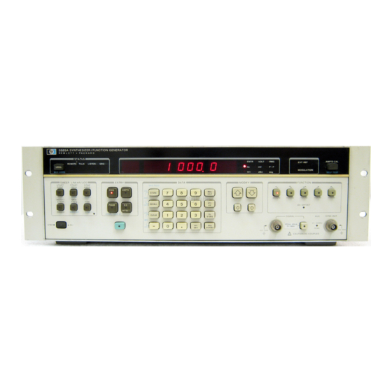
MODELS 3325A( ) AND 3325B( )
Headquarters, Department of the Army, Washington, DC
REPORTING OF ERRORS AND RECOMMENDED IMPROVEMENTS
You can help improve this publication. If you find any mistakes or if you
know of a way to improve the procedure, please let us know. Mail your letter
or DA Form 2028 to:
Command, ATTN: AMSAM-MMC-LS-LP, Redstone Arsenal, AL 35898-5230.
A reply will be furnished to you.
electronically to our e-mail address:
842-6546/DSN 788-6546
I.
II.
III
__________
*This bulletin supersedes TB 9-6625-2049-35, 15 January 1996.
*TB 9-6625-2049-35
SUPERSEDED COPY DATED 15 JANUARY 1996
HEWLETT-PACKARD
2 January 2001
Approved for public release; distribution is unlimited
Commander, U. S. Army Aviation and Missile
Test instrument identification............................
Forms, records, and reports................................
Calibration description .......................................
Equipment required............................................
Accessories required ...........................................
Preliminary instructions.....................................
Equipment setup.................................................
Harmonic distortion............................................
Amplitude modulation distortion........................
Square wave characteristics ...............................
Ramp retrace.......................................................
Frequency accuracy ............................................
Phase increment .................................................
Sine wave amplitude and flatness ......................
Square wave amplitude and flatness..................
You may also send in your comments
ls-lp@redstone.army.mil
or by FAX (256)
Page
1
2
2
2
3
2
4
4
5
5
6
6
7
6
8
7
9
9
10
9
11
10
12
11
13
13
14
14
15
16
Advertisement
Table of Contents

Related Manuals for HP 3325A


Summary of Contents for HP 3325A
-
Page 1: Table Of Contents
DEPARTMENT OF THE ARMY TECHNICAL BULLETIN CALIBRATION PROCEDURE FOR SYNTHESIZER/FUNCTION GENERATOR HEWLETT-PACKARD MODELS 3325A( ) AND 3325B( ) Headquarters, Department of the Army, Washington, DC Approved for public release; distribution is unlimited REPORTING OF ERRORS AND RECOMMENDED IMPROVEMENTS You can help improve this publication. If you find any mistakes or if you know of a way to improve the procedure, please let us know. -
Page 2: Paragraph Page
Final procedure ... IDENTIFICATION AND DESCRIPTION 1. Test Instrument Identification. calibration of Synthesizer/Function Generator, Hewlett-Packard, Models 3325A( ) and 3325B( ). The manufacturer's manuals and TM 11-6625-3065-14 were used as the prime data sources in compiling these instructions. referred to as the TI (test instrument) throughout this bulletin. - Page 3 Test instrument parameters Harmonic distortion (relative to fundamental at full output) Amplitude modulation Square wave Ramp retrace Frequency Sine wave Square wave Triangle Positive slope ramp Negative slope ramp Phase offset Amplitude Amplitude accuracy with no attenuation (attenuator range 1) into 50 load (no dc offset ) Flatness with no attenuation...
-
Page 4: Equipment Requirements
TB 9-6625-2049-35 Test instrument parameters Amplitude accuracy with offset attenuation (range 1) into 50 load Attenuator accuracy (these errors are additive with the amplitude accuracy errors) Amplitude output Amplitude (option 002) (high voltage output) Dc offset Dc offset (option 002) Dc plus ac Not verified below 50 Hz. -
Page 5: Accessories Required
5. Accessories Required. usage accessories, issued as indicated in paragraph 4 above, and are not listed in this calibration procedure. The following peculiar accessory is also required for this calibration: feedthrough termination, Hewlett-Packard, Model 11048C. Table 2. Minimum Specifications of Equipment Required Common name AUDIO ANALYZER FREQUENCY COUNTER... -
Page 6: Calibration Process
TB 9-6625-2049-35 6. Preliminary Instructions a. The instructions outlined in paragraphs 6 and 7 are preparatory to the calibration process. Personnel should become familiar with the entire bulletin before beginning the calibration. b. Items of equipment used in this procedure are referenced within the text by common name as listed in table 2. -
Page 7: Harmonic Distortion
8. Harmonic Distortion a. Performance Check (1) Connect TI EXT REF IN 1, 10 MHz to spectrum analyzer 10 MHz REF IN/OUT. (2) Connect TI SIGNAL to spectrum analyzer INPUT 50 . (3) Press keys and enter values using DATA keys as listed in (a) through (h) below: (a) SIGNAL off (option 002 not lit). - Page 8 TB 9-6625-2049-35 (a) 50 Hz. (b) ENTRY AMPTD. (c) 10 VOLT. (13) Set audio analyzer to measure distortion in dB. Audio analyzer indication will be -65 dB. (14) Perform (15) through (19) below for option 002 only. (15) Connect equipment as shown in figure 1 and set resistance standard to 470 . Figure 1.
-
Page 9: Amplitude Modulation Distortion
9. Amplitude Modulation Distortion a. Performance Check (1) Press keys and enter values using DATA keys as listed in (a) through (i) below: (a) SIGNAL off (option 002 not lit). (b) FUNCTION sine wave. (c) ENTRY FREQ. (d) 1 MHz. (e) ENTRY AMPTD. -
Page 10: Ramp Retrace
TB 9-6625-2049-35 (a) SIGNAL off (option 002 not lit). (b) FUNCTION square wave. (c) ENTRY FREQ. (d) 1 MHz. (e) ENTRY AMPTD. (f) 1 V RMS. (2) Connect TI SIGNAL to oscilloscope CH 1. (3) Set oscilloscope CH 1 COUPLING 50 (4) Set oscilloscope controls for duty cycle measurement. -
Page 11: Frequency Accuracy
(4) Set oscilloscope controls to measure ramp retrace time from the 90 to 10 percent points. Ramp retrace time will be 3 s. (5) Press FUNCTION negative ramp key and repeat (4) above. b. Adjustments. No adjustments can be made. 12. - Page 12 TB 9-6625-2049-35 (15) Set frequency counter controls to measure frequency. If frequency counter does not indicate between 59.99970 and 60.00030 MHz, perform b below. b. Adjustments (1) Disconnect TI rear panel 10 MHz OVEN OUTPUT from EXT REF IN option 001 only.
-
Page 13: Phase Increment
(12) Adjust A9R7 Fine Adj. (fig. 3) and A9 Coarse Adj. (fig. 3) for a minimum indication on frequency difference meter. (13) Disconnect TI from frequency difference meter. (14) Reconnect TI rear panel 10 MHz OVEN OUTPUT to EXT REF IN. 13. -
Page 14: Sine Wave Amplitude And Flatness
TB 9-6625-2049-35 (6) Adjust frequency counter sample rate control to HOLD and press RESET pushbutton. Record frequency counter indication. (7) Press ENTRY PHASE key and enter -1 deg using DATA keys. (8) Press frequency counter RESET pushbutton and record frequency counter indication. - Page 15 Test instrument settings ENTRY AMPTD 3.536 V RMS 3.536 V RMS 1.061 V RMS 1.061 V RMS 1.061 V RMS .3536 V RMS .3536 V RMS .3536 V RMS Press ENTRY DC OFFSET key and enter 1 mV using DATA keys. (5) Press keys and enter values using DATA keys as listed in (a) through (g) below: (a) ENTRY DC OFFSET.
-
Page 16: Square Wave Amplitude And Flatness
TB 9-6625-2049-35 b. Adjustments. No adjustments can be made. 15. Square Wave Amplitude and Flatness a. Performance Check (1) Connect TI SIGNAL to multimeter INPUT HI and LO using 50 termination. (2) Press keys and enter values using DATA keys as listed in (a) through (i) below: (a) SIGNAL off (option 002 not lit). - Page 17 (a) 1 kHz. (b) ENTRY AMPTD. (c) 1 V RMS. (d) AMPTD CAL. (7) Multimeter will indicate between 0.99 and 1.01 V ac. (8) Disconnect TI from multimeter. (9) Connect TI SIGNAL to oscilloscope CH 1 using 50 feedthrough termination. (10) Set oscilloscope controls to measure square wave amplitude.
- Page 18 TB 9-6625-2049-35 (6) Enter 10 kHz using DATA keys. Multimeter will indicate between 2.742 and 3.032 V ac. (7) Press keys and enter values using DATA keys as listed in (a) through (c) below: (a) FUNCTION positive ramp. (b) 100 Hz. (c) AMPTD CAL.
- Page 19 Test instrument DC OFFSET 14.99 -14.99 4.999 -4.999 1.499 -1.499 Perform (8) through (11) below for option 002 only. (8) Remove 50 feedthrough termination from equipment setup. (9) Press SIGNAL key on. (10) Enter 20 VOLT using DATA keys. Multimeter will indicate between 19.775 and 20.225 V dc.
- Page 20 TB 9-6625-2049-35 (4) Enter -4.5 VOLT using DATA keys. Multimeter will indicate between -4.35 and -4.65 V dc. (5) Press ENTRY FREQ key and enter 999.9 kHz using DATA keys. Multimeter will indicate between -4.44 and -4.56 V dc. (6) Press ENTRY DC OFFSET key and enter 4.5 VOLT using DATA keys. Multimeter will indicate between 4.44 and 4.56 V dc.
- Page 21 (a) ENTRY FREQ. (b) 100 kHz. (c) ENTRY AMPTD. (d) 10 V RMS. (e) AMPTD CAL. (5) Multimeter will indicate between 9 and 11 V ac. (6) Press keys and enter values using DATA keys as listed in (a) through (f) below: (a) FUNCTION square wave.
- Page 22 TB 9-6625-2049-35 Figure 5. Power supply assembly A2 – test instrument top view. (5) Press presently active FUNCTION key to remove ac output and activate ENTRY DC OFFSET key (lit). (6) Enter 0 VOLT using DATA keys and press AMPTD CAL key. (7) Connect multimeter INPUT HI to TP AMP OUT (fig.
- Page 23 By Order of the Secretary of the Army: Official: JOEL B. HUDSON Administrative Assistant to the Secretary of the Army 0029703 DISTRIBUTION: To be distributed in accordance with IDN 342200, requirements for calibration procedure TB 9-6625-2049-35. TB 9-6625-2049-35 ERIC K. SHINSEKI General, United States Army Chief of Staff PIN: 052316-000...