Table of Contents
Advertisement
Available languages
Available languages
Sharpening
Center
Affilage
Du Centre
Afiladura
Del Centro
INSTRUCTIVO DE OPERACIÓN, CENTROS
DE SERVICIO Y PÓLIZA DE GARANTÍA.
LÉASE ESTE INSTRUCTIVO
ANTES DE USAR EL PRODUCTO.
A26589 - 03-25-08
Copyright © 2008 Delta Machinery
Instruction Manual
Manuel d'utilisation
Manual de instrucciones
FRANÇAIS (22)
ESPAÑOL (42)
www.deltaportercable.com
(800) 223-7278 - US
(800) 463-3582 - CANADA
23-710
Advertisement
Table of Contents

Related Manuals for Delta 23-710


Summary of Contents for Delta 23-710
-
Page 1: Instruction Manual
Manual de instrucciones FRANÇAIS (22) ESPAÑOL (42) INSTRUCTIVO DE OPERACIÓN, CENTROS DE SERVICIO Y PÓLIZA DE GARANTÍA. LÉASE ESTE INSTRUCTIVO ANTES DE USAR EL PRODUCTO. www.deltaportercable.com (800) 223-7278 - US (800) 463-3582 - CANADA A26589 - 03-25-08 Copyright © 2008 Delta Machinery... -
Page 2: Table Of Contents
If you have any questions relative to its application DO NOT use the product until you have written Delta Machinery and we have advised you. Contact us online at www.deltaportercable.com or by mail at Technical Service Manager, Delta Machinery, 4825 Highway 45 North, Jackson, TN 38305. -
Page 3: General Safety Rules
“OFF” position. An accidental start-up can cause injury. replaced with Delta or factory authorized replacement 22. MAkE YOUR WORkSHOP CHILDPROOF WITH parts. Damaged parts can cause further damage to the PADLOCkS, MASTER SWITCHES, OR BY REMOVINg machine and/or injury. -
Page 4: Additional Specific Safety Rules
ADDITIONAL SPECIFIC SAFETY RULES Failure to follow these rules may result in serious personal injury. DO NOT OPERATE THIS MACHINE until it is different types of workpieces (wood, steel, or alumi- completely assembled and installed according to the num). Combining wood and metal dust can create instructions. -
Page 5: Power Connections
POWER CONNECTIONS A separate electrical circuit should be used for your machines. This circuit should not be less than #12 wire and should be protected with a time delay fuse. NOTE: Time delay fuses should be marked “D” in Canada and “T” in the US. If an extension cord is used, use only 3-wire extension cords which have 3-prong grounding type plugs and matching receptacle which will accept the machine’s plug. -
Page 6: Functional Description
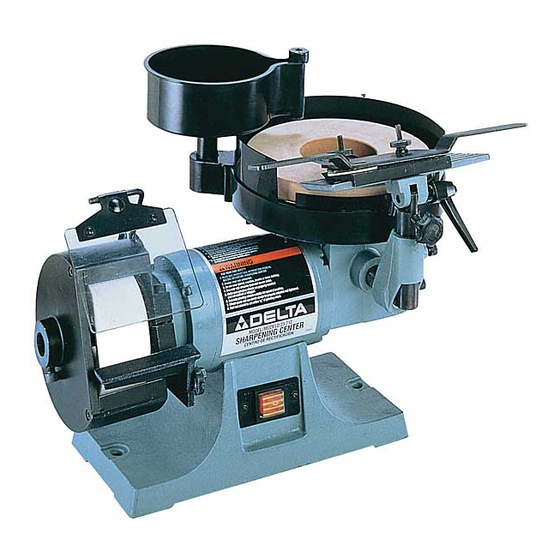
FOREWORD The Delta Industrial Sharpening Center Model 23-710 has a 1/5 HP motor. It also comes with a 5” diameter, 120 grit aluminum oxide dry wheel, an 8” diameter, 1000-grit wet wheel, a tool rest and base, a sliding tool holder, a water tank, eye shield and wrenches. -
Page 7: Assembly
UNPACkINg AND CLEANINg Carefully unpack the machine and all loose items from the shipping container(s). Remove the rust-preventative oil from unpainted surfaces using a soft cloth moistened with mineral spirits, paint thinner or denatured alcohol. Do not use highly volatile solvents such as gasoline, naphtha, acetone or lacquer thinner for cleaning your machine. - Page 8 ASSEMBLINg AND ADJUSTINg TOOL REST FOR DRY WHEEL 1. Assemble dry wheel tool rest (A) Fig. 7, to mounting arm (B) using flat washer (C), lockwasher (D) and 5/8” long hex head screw (E). Place a lockwasher then a flat washer on the hex head screw, then assemble tool rest to mounting arm as shown in Fig.
- Page 9 ASSEMBLINg AND ADJUSTINg TOOL AND CHISEL HOLDER 1. Take the tool and chisel holder base and insert its mounting post (A) Fig. 11, into hole (B) in the front of the machine, and tighten screw (C) against groove (E) of mounting post. Use the provided wrench (D) Fig. 2.
- Page 10 6. Place tool and chisel holder (K) Fig. 15, in position on base (J). Fig. 15 7. Fig. 16, illustrates tool and chisel holder (K) in posi- tion on tool rest base (J). 8. To raise or lower the tool and chisel holder assembly (E) Fig.
- Page 11 2. The water tank (B) Fig. 19, can be rotated to direct the water from the spigot (D) onto the grinding wheel. The ideal position of the spigot (D) would be to the center (C) of the grinding wheel. 3. To control the flow of water from the spigot (D) Fig. 19, turn knob (E).
-
Page 12: Operation
OPERATION To reduce the risk of injury, turn unit off and disconnect it from power source before installing and remov- ing accessories, before adjusting or when making repairs. An accidental start-up can cause injury. OPERATIONAL CONTROLS AND ADJUSTMENTS USINg TOOL AND CHISEL HOLDER The tool and chisel holder is supplied as standard equip ment with your sharpening center and is ideal for sharp en ing wood chisels, plane irons, some lathe turn-... - Page 13 STARTINg AND STOPPINg MACHINE Make sure that the switch is in the “OFF” position before plugging cord into outlet. Do not touch the plug’s metal prongs when unplugging or plugging in the cord. In the event of a power outage (such as a breaker or fuse trip), always move the switch to the “OFF”...
- Page 14 3. Remove the tool rest and mounting post (E) Fig. 35, from the wet wheel side of the machine and insert post of tool rest assembly into hole (F). Tighten screw (G) into groove of mounting post. All controls and ad- justments for the tool rest are explained in the sec- tion “ASSEMBLING AND AD JUST ING TOOL AND CHISEL HOLDER.”...
- Page 15 4. Place sliding tool rest (K) Fig. 40, in position on base (J). Fig. 40 5. Fig. 41, illustrates sliding tool rest (K) in position on tool rest base (J). 6. To level sliding tool rest (K) Fig. 42, with the wet grind- ing wheel, loosen screw (L), rotate complete tool rest base (E) right or left until tool rest (K) is level with the wet grinding wheel and tighten screw (L).
- Page 16 8. To tilt the sliding tool rest (K) Fig. 45, to conform with the angle of the knife to be sharpened, turn the tool rest tilting knob (P). Fig. 45 USINg ACCESSORY 23-715 SLIDINg TOOL REST ON DRY WHEEL When sharpening planer or jointer knives that have deep nicks, the knives can first be rough ground on the dry grinding wheel, using the sliding tool rest, before fine sharp en ing is performed on the wet wheel.
- Page 17 Fig. 49 Fig. 50 3. Remove sliding tool rest and mounting post (E) Fig. 49, from the wet wheel side of the machine and insert post of tool rest assembly into hole (F). Tighten screw (G) into groove (J) of mounting post (E). 4.
- Page 18 3. Place sliding tool rest (G) Fig. 53, onto the tool rest base (H) as shown. 4. Adjust the height of tool rest base (H) Fig. 54, by moving locking lever (J) to the right and turning rais- ing and lowering knob (K) until knife (B) Fig. 53, lightly touches grinding wheel (L).
- Page 19 REPLACINg WET gRINDINg WHEEL To reduce the risk of injury, turn unit off and disconnect it from power source before installing and re- moving accessories, before adjusting or when making repairs. An accidental start-up can cause injury. 1. Using the wrench (A) Fig. 58, supplied, remove the wheel locking nut (B).
-
Page 20: Troubleshooting
TROUBLESHOOTINg For assistance with your machine, visit our website at www.deltaportercable.com for a list of service centers or call the DELTA Machinery help line at 1-800-223-7278 (In Canada call 1-800-463-3582). MAINTENANCE To reduce the risk of injury, turn unit off and disconnect it from power source before installing and removing accessories, before adjusting or when making repairs. -
Page 21: Service
Two Year Limited New Product Warranty Delta will repair or replace, at its expense and at its option, any new Delta machine, machine part, or machine accessory which in normal use has proven to be defective in workmanship or material, provided that the customer returns the product prepaid to a Delta factory service center or authorized service station with proof of purchase of the product within two years and provides Delta with reasonable opportunity to verify the alleged defect by inspection. - Page 22 Il y a de certaines applications pour lequel outils et l'équipement sont conçus. La Delta Machinery recommande avec force que ce produit n'ait pas modifié et/ou utilisé pour l'application autrement que pour lequel il a été conçu.
- Page 23 13. UTILISER LES ACCESSOIRES RECOMMANDÉS. L’utilisation de substances toxiques. Portez toujours des dispositifs de d’accessoires non recommandés par Delta peut endommager la protection respiratoire homologués par NIOSH/OSHA, appropriés machine et blesser l’utilisateur.
- Page 24 RÈgLES DE SÉCURITÉ SPÉCIFIQUES SUPPLÉMENTAIRES L'inobservation de ces règles risque d'entraîner des blessures graves. NE PAS FAIRE FONCTIONNER CET APPAREIL avant qu’il graves. ne soit entièrement assemblé et installé conformément aux 16. NETTOYER L’APPAREIL soigneusement lors du traitement directives. Un appareil mal assemblé peut provoquer des de différents types de matériaux (bois, acier ou aluminium).
- Page 25 RACCORDEMENTS ÉLECTRIQUES Un circuit électrique séparé doit être utilisé pour les machines. Ce circuit doit utiliser un câble de calibre 12 au minimum et doit être protégé par un fusible temporisé. REMARQUE : les fusibles temporisés devraient avoir l’inscription « D » au Canada et «...
-
Page 26: Cordon De Rallonge
AVANT-PROPOS Le système industriel d’affûtage Delta, modèle 23-710, comporte un moteur de 1/5 hp. Il est également livré avec une meule à sec de 127 mm (5 po) de diamètre, 120 grains, une meule à eau de 203,2 mm (8 po) de diamètre, 1 000 grains, un porte-outil et une base, un porte-outil coulissant, un bac à... - Page 27 DÉSEMBALLAgE ET NETTOYAgE Désemballer soigneusement la machine et toutes les pièces de ou des emballage(s) d’expédition. Retirer l’huile anti- corrosion des surfaces non peintes à l’aide d’un chiffon doux humidifié avec de l’alcool, du diluant à peinture ou de l’alcool dénaturé. N’utiliser pas de solvants hautement volatils tel l’essence, le naphte, l’acétone ou du diluant à...
- Page 28 ASSEMBLAgE ET RÉgLAgE DU PORTE- OUTIL POUR MEULAgE À SEC 1. Fixer le porte-outil (A) pour meulage à sec, fig. 7, au bras de montage (B) au moyen de la rondelle plate (C), de la rondelle de blocage (D) et de la longue vis à...
- Page 29 ASSEMBLAgE ET RÉgLAgE DU PORTE- OUTIL ET PORTE-BÉDANE 1. Prendre la base du porte-outil et porte-bédane et in- sérer sa tige de montage (A), fig. 11, dans le trou (B) à l’avant de l’appareil puis serrer la vis (C) contre la rainure (E) de la tige de montage.
- Page 30 6. Placer le porte-outil et le porte-bédane (K), fig. 15, en position sur la base (J). 7. La figure 16 illustre le porte-outil et le porte-bédane (K) en position sur la base (J) du porte-outil. 8. Pour abaisser ou hausser le module du porte-outil et le porte-bédane (E), fig.
- Page 31 2. Il est possible d’orienter le bac à eau (B), fig. 19, et diriger l’eau sortant du robinet (D) sur la meule. Idéalement, régler le robinet (D) de sorte qu’il soit au centre (C) de la meule. 3. Pour contrôler le débit d’eau du robinet (D), fig. 19, tourner le bouton (E).
- Page 32 FONCTIONNEMENT Pour réduire le risque de blessures corporelles graves, éteindre l’outil et le débrancher avant d’installer et de retirer tout accessoire, avant d'ajuster ou de modifier les réglages ou lors de réparations. Un démar- rage accidentel peut provoquer des blessures. L'OPERATION CONTROLE DE LE ET LES AJUSTEMENTS UTILISATION DU PORTE-OUTIL ET PORTE-...
- Page 33 MISE EN MARCHE ET HORS FONCTION DE L’APPAREIL S’assurer que l’interrupteur se trouve sur la position d’arrêt avant de brancher le cordon d’alimentation dans la prise. Ne pas toucher aux lames métalliques de la fiche lors du branche- ment ou débranchement du cordon. En cas de panne d’électricité...
- Page 34 3. Retirer le porte-outil et la tige de montage (E), fig. 35, du côté de la meule à eau de l’appareil et insérer la tige du module du porte-outil dans le trou (F). Ser- rer la vis (G) dans la rainure de la tige de montage. Rechercher toutes les directives pertinentes aux commandes et aux réglages du porte-outil sous la rubrique «...
- Page 35 4. Installer le porte-outil coulissant (K), fig. 40, en posi- tion sur la base (J). 5. La figure 41 illustre le porte-outil coulissant (K) en po- sition sur la base du porte-outil (J). 6. Pour mettre le porte-outil coulissant (K), fig. 42, de niveau avec la meule à...
- Page 36 8. Pour incliner le porte-outil coulissant (K), fig. 45, à l’angle correspondant au couteau à affûter, tourner le bouton d’inclinaison (P) du porte-outil. Fig. 45 UTILISATION DU PORTE-OUTIL COULIS- SANT ACCESSOIRE 23-715 AVEC UNE MEULE SÈCHE Lors de l’affûtage de couteaux de raboteuses ou de dé- gauchisseuses qui comportent des entailles profondes, il est possible d’affûter grossièrement le bord tranchant au moyen de la meule à...
- Page 37 Fig. 49 Fig. 50 3. Retirer le porte-outil coulissant et la tige de montage (E), fig. 49, du côté de la meule à eau de l’appareil et insérer la tige du module du porte-outil dans le trou (F). Serrer la vis (G) dans la rainure (J) de la tige de montage (E).
- Page 38 3. Installer le porte-outil coulissant (G), fig. 53, sur la base du porte-outil (H) comme montré. 4. Régler la hauteur de la base du porte-outil (H), fig. 54, en déplaçant le levier de blocage (J) vers la droite et en tournant le bouton (K) pour abaisser le couteau (B) ou le relever, fig.
- Page 39 REMPLACEMENT D’UNE MEULE À EAU Pour réduire le risque de blessures cor- porelles graves, éteindre l’outil et le débrancher avant d’installer et de retirer tout accessoire, avant d'ajuster ou de modifier les réglages ou lors de réparations. Un démarrage accidentel peut provoquer des blessures. 1.
- Page 40 DEPANNAgE Pour l'assistance avec votre outil, visiter notre site web à www.deltaportercable.com pour une liste de centres de maintenance ou appeler la ligne d'aide de Delta Machinery à 1-800-223-7278. (Canada: 1-800-463-3582). ENTRETIEN Pour réduire le risque de blessures corporelles graves, éteindre l’outil et le débrancher avant d’installer et de retirer tout accessoire, avant d'ajuster ou de modifier les réglages ou lors de réparations.
- Page 41 à condition que le client retourne le produit (transport payé d'avance) au centre de réparation de l'usine Delta ou à un centre de réparation autorisé...
- Page 42 Si usted tiene cualquiera pregunta el pariente a su aplicación no utiliza el producto hasta que usted haya escrito Delta Machinery y nosotros lo hemos aconsejado. La forma en línea del contacto en www. deltaportercable. com o por correoTechnical Service Manager, Delta Machinery, 4825 Highway 45 North, Jackson, TN 38305.
- Page 43 13. UTILICE ACCESORIOS RECOMENDADOS. La utilización por NIOSH/OSHA que se ajuste apropiadamente y sea de accesorios y aditamentos no recomendados por Delta adecuada para la exposición al polvo, y lávese las áreas podría causar daños a la máquina o lesiones al usuario.
- Page 44 NORMAS ESPECÍFICAS ADICIONALES DE SEgURIDAD Si no se siguen estas normas, el resultado podría ser lesiones personales graves. NO UTILICE ESTA MÁQUINA hasta que esté 15. NO ARRANQUE NUNCA LA MÁQUINA con la pieza completamente montada e instalada de acuerdo con las de trabajo contra la rueda de amolar.
- Page 45 CONEXIONES A LA FUENTE DE ALIMENTACIÓN Debe utilizarse un circuito eléctrico independiente para las máquinas. Este circuito no debe ser menor a un cable Nº 12 y debe estar protegido con un fusible de acción retardada. NOTA: Los fusibles de acción retardada deben estar marcados “D” en Canadá...
- Page 46 PROLOgO El Centro de afilado industrial Delta modelo 23-710 tiene un motor de 1/5 hp. Además, tiene un disco de óxido de aluminio para esmerilar en seco, de grano 120 y 127 mm (5") de diámetro; un disco para esmerilar en húmedo, de grano 1.000 y 203 mm (8") de diámetro;...
- Page 47 DESEMPAQUETADO Y LIMPIEZA Desembale cuidadosamente la máquina y todos los elementos sueltos del o los contenedores de envío. Retire el aceite anticorrosivo de las superficies sin pintura con un paño suave humedecido con alcohol mineral, solvente o alcohol desnaturalizado. No use solventes volátiles como gasolina, nafta, acetona o solvente de barniz para limpiar la máquina.
- Page 48 ENSAMBLAJE Y AJUSTE DEL SOPORTE DE HERRAMIENTAS PARA DISCO PARA ESMERILAR EN SECO 1. Ensamble el soporte de herramientas para disco para esmerilar en seco (A), figura 7, al brazo de montaje (B) con una arandela plana (C), una arandela de bloqueo (D) y un tornillo de cabeza hexagonal de 16 mm (5/8") de largo (E).
- Page 49 ENSAMBLAJE Y AJUSTE DEL SUJETADOR DE HERRAMIENTAS Y CINCEL 1. Tome el sujetador de herramientas y cincel, intro- duzca su poste de montaje (A), figura 11, en el orifi- cio (B) que está en la parte delantera de la máquina y ajuste el tornillo (C) contra la ranura (E) del poste de montaje.
- Page 50 6. Coloque el sujetador de herramientas y cincel (K), figura 15, en posición sobre la base (J). 7. La figura 16 muestra el sujetador de herramientas y cincel (K) en posición sobre la base del soporte de herramientas (J). 8. Para levantar o bajar el conjunto del sujetador de herramientas y cincel (E), figura 17, consulte el PASO 9.
- Page 51 2. El tanque de agua (B), figura 19, se puede girar para orientar el agua del grifo (D) hacia el disco para es- merilar. La orientación ideal del grifo (D) es el centro (C) del disco para esmerilar. 3. Para controlar el flujo de agua del grifo (D), figura 19, gire la perilla (E).
- Page 52 OPERACIÓN CONTROLES Y AJUSTES OPERACIONALES USO DEL SUJETADOR DE HERRAMIENTAS Y CINCEL Para reducir el riesgo de lesiones personales graves, apague la herramienta y desconéctela de la fuente de alimentación antes de instalar y retirar accesorios, ajustar o cambiar configuraciones o realizar reparaciones.
- Page 53 ENCENDIDO Y APAgADO DE LA MÁQUINA Asegúrese de que el interruptor esté en la posición de “APAgADO” (OFF) antes de enchufar el cable de alimentación en el tomacorriente. No toque las patas de metal del enchufe al enchufar o desenchufar el cable. En el caso de un corte eléctrico (por ejemplo por un interruptor o fusible quemados) bloquee siempre el interruptor en la posición de apaga-...
- Page 54 3. Quite el soporte de herramientas y el poste de mon- taje (E), figura 35, del costado del disco de esmerilar en húmedo de la máquina e introduzca el poste del conjunto del soporte de herramientas en el orificio (F). Ajuste el tornillo (G) en la ranura del poste de montaje.
- Page 55 4. Coloque el soporte de herramientas deslizante (K), figura 40, en posición sobre la base (J). Fig. 40 5. La figura 41 muestra el soporte de herramientas deslizante (K) en posición sobre la base del soporte de herramientas (J). 6. Para nivelar el soporte de herramientas deslizante (K), figura 42, con el disco para esmerilar en húmedo, afloje el tornillo (L), gire toda la base del soporte de herramientas (E) hacia la derecha o la izquierda hasta...
- Page 56 8. Para inclinar el soporte de herramientas deslizante (K), figura 45, de acuerdo con el ángulo de la cuchil- la que desea afilar, gire la perilla de inclinación del soporte de herramientas (P). USO DEL SOPORTE DE HERRAMIENTAS DESLIZANTE ACCESORIO 23-715, CON EL DISCO PARA ESMERILAR EN SECO Cuando afile cuchillas de cepilladoras y empalmadoras que tienen muescas profundas, antes de realizar el afilado...
- Page 57 Fig. 49 Fig. 50 3. Quite el soporte de herramientas deslizante y el poste de montaje (E), figura 49, del costado del disco de esmerilar en húmedo de la máquina e introduzca el poste del conjunto del soporte de herramientas en el orificio (F).
- Page 58 3. Coloque el soporte de herramientas deslizante (K), figura 53, en la base del soporte de herramientas (H), como se muestra. 4. Para ajustar la altura de la base del soporte de her- ramientas (H), figura 54, mueva la palanca de blo- queo (J) hacia la derecha y gire la perilla de elevación y descenso (K) hasta que la cuchilla (B), figura 53, toque ligeramente el disco para esmerilar (L).
- Page 59 REEMPLAZO DEL DISCO PARA ESMERILAR EN HÚMEDO Para reducir el riesgo de lesiones per- sonales graves, apague la herramienta y desconéctela de la fuente de alimentación antes de instalar y retirar accesorios, ajustar o cambiar configuraciones o realizar reparaciones. Un arranque accidental podría causar lesiones.
- Page 60 Para obtener asistencia para su máquina, visite nuestro sitio Web en www.deltaportercable.com para tener acceso a una lista de centros de servicio o llame a la línea de ayuda de Delta Machinery al 1-800-223-7278. (En Canadá, llame al 1-800-463-3582.) MANTENIMIENTO Para reducir el riesgo de lesiones personales graves, apague la herramienta y desconéctela de la...
- Page 61 Puesto que los accesorios con excepción de ésos ofrecidos por Delta no se han probado con este producto, el uso de tales accesorios podría ser peligroso. Para la operación más segura, solamente el delta recomendó los accesorios se debe utilizar con este producto.
- Page 62 Si se encuentra en México, por favor llame al (55) 5326 7100 por f Si se encuentra en U.S., avor llame al (888) 848-5175 ESPECIFICACIONES MODEL 23-710 Tensión de alimentación: 120 V AC~ Consumo de corriente: 15 A Frecuencia de operación: 60 Hz Rotación sin carga:...
- Page 63 Delta o una estación de servicio autorizado Delta, con un comprobante de compra del producto, dentro del plazo de dos años y dé a Delta una oportunidad razonable de verificar el supuesto defecto mediante la realización de una inspección.
-
Page 64: Delta Machinery
2 BY 4 ® , 890 ™ , Air America ® , AIRBOSS ™ , Auto-Set ® , B.O.S.S. ® , Bammer ® , Biesemeyer ® , Builders Saw ® , Charge Air ® , Charge Air Pro ® , CONTRACTOR SU- PERDUTY ® , Contractor's Saw ® , Delta ® , DELTA ® , Delta Industrial ® , DELTA MACHINERY & DESIGN ™ , Delta Shopmaster and Design ® , Delta X5 ® , Deltacraft ® , DELTAGRAM ®...