Table of Contents
Advertisement
Advertisement
Table of Contents

Related Manuals for Delta VERSA-FEEDER 36-865


Summary of Contents for Delta VERSA-FEEDER 36-865
- Page 1 VERSA-FEEDER (Model 36-865) Stock Feeder PART NO. 1348009 - 03-31-05 Copyright © 2005 Delta Machinery To learn more about DELTA MACHINERY visit our website at: www.deltamachinery.com. For Parts, Service, Warranty or other Assistance, 1-800-223-7278 ( 1-800-463-3582). please call In Canada call...
-
Page 2: Table Of Contents
NOT be modified and/or used for any application other than for which it was designed. If you have any questions relative to its application DO NOT use the product until you have written Delta Machinery and we have advised you. -
Page 3: Safety Guidelines
SAFETY GUIDELINES - DEFINITIONS It is important for you to read and understand this manual. The information it contains relates to protecting YOUR SAFETY and PREVENTING PROBLEMS. The symbols below are used to help you recognize this information. Indicates an imminently hazardous situation which, if not avoided, will result in death or serious injury. Indicates a potentially hazardous situation which, if not avoided, could result in death or serious injury. -
Page 4: General Safety Rules
Damage to the machine and/or injury may result. 13. USE RECOMMENDED ACCESSORIES. The use of accessories and attachments not recommended by Delta may cause damage to the machine or injury to the user. IMPORTANT SAFETY INSTRUCTIONS 14. -
Page 5: Additional Specific Safety Rules
ADDITIONAL SPECIFIC SAFETY RULES FAILURE TO FOLLOW THESE RULES MAY RESULT IN SERIOUS PERSONAL INJURY. DO NOT OPERATE THIS MACHINE until it is completely assembled and installed according to the instructions. A machine incorrectly assembled can cause serious injury. OBTAIN ADVICE from your supervisor, instructor, or another qualified person if you are not thoroughly familiar with the operation of this machine. -
Page 6: Power Connections
POWER CONNECTIONS A separate electrical circuit should be used for your machines. This circuit should not be less than #12 wire and should be protected with a 20 Amp time lag fuse. If an extension cord is used, use only 3-wire extension cords which have 3- prong grounding type plugs and matching receptacle which will accept the machine’s plug. -
Page 7: Functional Description
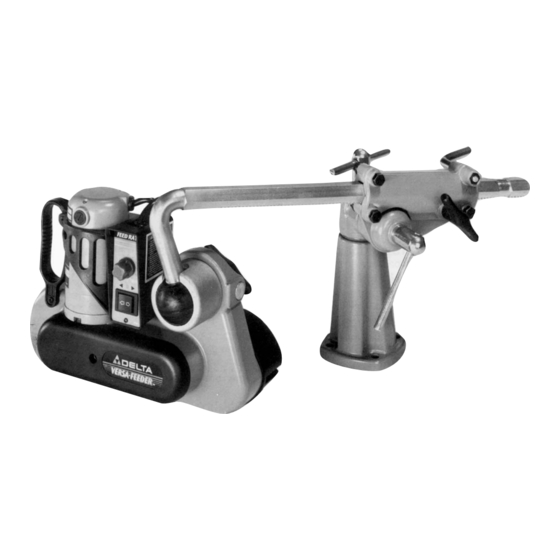
FUNCTIONAL DESCRIPTION FOREWORD Delta Model 36-865 Versa-Feeder Stock Feeder (Variable Speed) includes a 1/8 hp 120V reversing motor. This model comes with three rubber feed rollers, a vertical and horizontal adjustable support arm, and a base mounting bracket. NOTICE: The photo on the manual cover illustrates the current production model. All other illustrations contained in the manual are representative only and may not depict the actual color, labeling, or accessories and are intended to illustrate technique only. - Page 8 1. Stock Feeder 2. Overarm 3. Overarm Clamp Assembly 4. Swivel Joint 5. Base 6. Pivot Ball 7. Shaft 8. 14MM and 17MM Open-end Wrench 9. T-Handle Screw 10. Locking Lever 11. M8 Flat Washer 12. M8 Hex Nut 13. 3/8 Lockwasher 14.
-
Page 9: Assembly
ASSEMBLY TOOLS REQUIRED 3/8" Wrench 7/16" Wrench 5/16" Wrench 1/2" Wrench ASSEMBLY TIME ESTIMATE Approximately 2-4 hours The Versa-Feeder can be assembled as shown in Figs. 3 or Fig. 4, depending on the operation and type of wood- working machine on which the stock feeder will mount. The following instructions pertain to the assembly in Fig. 3. IMPORTANT: Familiarize yourself with the following assembly instructions and the components of the machine. - Page 10 2. Place the pivot ball housing (F) Fig. 7 in the sleeve (G) of stock feeder. NOTE: Position the slot in the pivot ball housing (F) "up" (Fig. 8). 3. Insert the overarm (B) Fig. 9 with pivot ball (A) attached, through the housing (F) until the pivot ball (A) is inside the housing (F).
- Page 11 5. Insert the metal shaft (J) Fig. 12 through the hole in the side of the sleeve (G) and into the wide slots of the pivot cover (H) Fig. 12. Thread the T-handle screw (K) Fig. 13 into the hole of the shaft (J), just enough to hold the pivot pin assembly in position.
- Page 12 9. Insert the end of the overarm assembly (B) Fig. 18 into the clamp assembly (M) until the gear inside the clamp assembly meshes with the rack on the overarm. Turn the T-handle screw (S) counter-rclockwise until the clamp assembly (M) is securely positioned on the overarm assembly (B). IMPORTANT: Depending on the application, the overarm assembly (B) can be inserted into either end of the clamp assembly (M).
- Page 13 ALTERNATE ASSEMBLY ARRANGEMENT To assemble the Versa-Feeder in the mounting arrangement shown in Fig. 4, attaching the pivot ball to the overarm clamp assembly differs slightly. To assemble: 1. Remove the overarm (A) Fig. 24 from the overarm clamp assembly (B). 2.
- Page 14 6. Insert the straight end of the overarm (A) Fig. 29 through the housing (E). Attach the pivot ball (F) Fig. 29 to the over- arm (A) with a 3/8-16 x 1" socket hex head screw and lock-washer (K) Fig. 30. NOTE: Make certain that the screw and lockwasher (K) are recessed inside pivot ball (F).
-
Page 15: Operation
MOUNTING THE VERSA-FEEDER TO A MACHINE TABLE Decide on the location you wish to mount the Versa-Feeder on your machine. Refer to Figs. 44, 45, and 46 for assistance when mounting the stock feeder assembly to a table saw, jointer, or shaper. To mount the stock feeder assembly to a machine table: 1. -
Page 16: Machine Use
MACHINE USE DISCONNECT MACHINE FROM THE POWER SOURCE. You can rotate the entire feeder assembly (A) Fig. 38 360 degrees in the mounting bracket by loosening the locking lever (B). To raise or lower the feeder assembly (A) Fig. 38 , loosen the lever (C) and move the overarm (D). - Page 17 REPLACING FEED ROLLERS Each feed roller is removable for repair or replacement. To remove the feed rollers: DISCONNECT MACHINE FROM THE POWER SOURCE. 1. Loosen the three screws (A) Fig. 42 and remove the cover (B). 2. Remove the retaining ring (C) Fig. 43, and lift off the feed roller (D). 3.
-
Page 18: Troubleshooting
(C). For assistance with your machine, visit our website at www.deltamachinery.com for a list of service centers or call the DELTA Machinery help line at 1-800-223-7278 (In Canada call 1-800-463-3582). BRUSH INSPECTION AND REPLACEMENT DISCONNECT MACHINE FROM THE POWER SOURCE. -
Page 19: Service
Two Year Limited New Product Warranty Delta will repair or replace, at its expense and at its option, any new Delta machine, machine part, or machine accessory which in normal use has proven to be defective in workmanship or material, provided that the customer returns the product prepaid to a Delta factory service center or authorized service station with proof of purchase of the product within two years and provides Delta with reasonable opportunity to verify the alleged defect by inspection. - Page 20 Phone: (604) 420-0102 Fax: (604) 420-3522 The following are trademarks of PORTER-CABLE • DELTA (Las siguientes son marcas registradas de PORTER-CABLE • DELTA S.A.) (Les marques suivantes sont des marques de fabriquant de la PORTER-CABLE • DELTA): Auto-Set Contractor’s Saw II™, Delta ®...