Peavey PV14 Operating Manual
Compact mixer
Hide thumbs
Also See for PV14:
- Operating manual (48 pages) ,
- Operation manual (36 pages) ,
- Operating manual (5 pages)
Advertisement
Advertisement
Table of Contents

Related Manuals for Peavey PV14


Summary of Contents for Peavey PV14
- Page 1 ™ ™ ™ 10 • PV 14 • PV Compact Mixer Operating Manual www.peavey.com...
- Page 2 ATTENTION: Afin de réduire le risque de choc électrique, ne pas enlever le couvercle. Il ne se trouve à l’intérieur aucune pièce pouvant être reparée par l’utilisateur. Confiez I’entretien et la réparation de l’appareil à un réparateur Peavey agréé. AVIS: Dans le but de reduire les risques d’incendie ou de decharge electrique, cet appareil ne doit pas etre expose a la pluie ou a l’humidite et aucun objet rempli de liquide, tel qu’un vase, ne doit...
-
Page 3: Important Safety Instructions
IMPORTANT SAFETY INSTRUCTIONS WARNING: When using electrical products, basic cautions should always be followed, including the following: Read these instructions. Keep these instructions. Heed all warnings. Follow all instructions. Do not use this apparatus near water. Clean only with a dry cloth. Do not block any of the ventilation openings. -
Page 4: Features
ENGLISH 10, PV 14 and PV ™ ™ ™ Compact Mixers Congratulations on purchasing the Peavey PV ™ 10, PV ™ 14, or the PV ™ 20 Compact Mixer. The PV ™ 10, PV ™ 14, and PV ™ 20 are studio-quality mixing consoles designed to meet diverse needs while occupying a small space. -
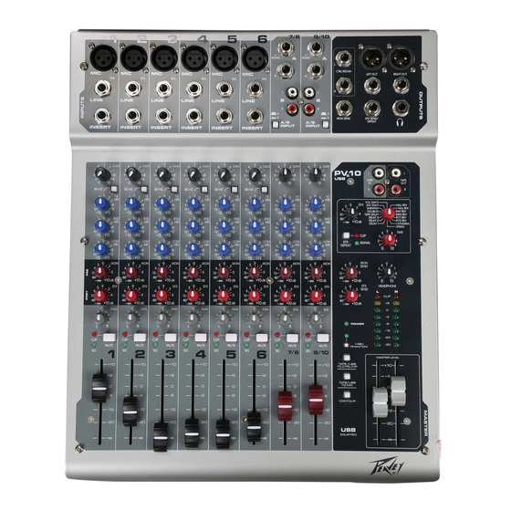
Page 5: Front Panel
Front Panel Gain This control establishes the nominal operating level for the channel. GAIN The input gain can be adjusted over a wide range to compensate for soft voices or very loud drums. To maximize the signal-to-noise ratio, the gain 80 HZ should be set to the proper level, with the channel Fader (12) set to 0. - Page 6 Front Panel Signal LED The signal LED lights when the channel level reaches approxi- mately -20 dBu. This not only indicates which channels are PV20 active, but also serves as a mini level meter. TAPE TAPE Fader The channel Fader is the channel output control, which sets VOC ENH2 HALL REV VOC ENH1...
- Page 7 Front Panel EFX Time This control adjusts the time of the particular reverb or delay. Green Signal LED and Red Clip LED The green Signal LED and red Clip LED are used to set the operating input level to the PV™10, PV™14, and PV™20 effects processors.
-
Page 8: Rear Panel
Front Panel Phantom Power Switch This Switch applies +48 VDC voltage to the input XLR connectors to power microphones requiring phan- tom power. If phantom power is used, do not connect unbalanced dynamic microphones or other devices to the XLR inputs. - Page 9 Rear Panel Insert The 1⁄4” TRS connectors allow external signal processors to be inserted into the channel signal path. Tip=Send; Ring=Return; Sleeve=Ground. Stereo (1⁄4”) Inputs These 1⁄4” unbalanced inputs work as a stereo line input using both jacks or as a mono input if the con- nection is made to the left/mono input only.
- Page 10 2 - POSITIVE SLEEVE = GND 3 - NEGATIVE (GND) peavey.com POWER DIGITAL AUDIO PORT A PRODUCT OF PEAVEY ELECTRONICS CORP. DESIGNED IN USA MADE IN CHINA 100 - 240V 50/60Hz COMPUTER RECORD 27 WATTS LEVEL Power Switch Depressing the power switch supplies power to the unit.
-
Page 11: Block Diagram
™ ™ ™ Block Diagram-PV 10, PV 14 & PV... -
Page 12: Series Specifications
10, PV 14 & PV 20 Series Specifications ™ ™ ™ Inputs Input Levels Function Input Z Input Gain Bal/ Connector (ohms min) Setting Min** Nominal* Unbal Microphone 2.2k Max Gain -76 dBu -56 dBu -38 dBu XLR Pin 1 Gnd (150 ohms) (60 dB) Pin 2 (+) -
Page 13: Frequency Response
PV20: 22.125" wide x 15.75" deep 3.5" high (30.80cm x 37.47cm x 8.89cm) (56.2cm x 40.0cm x 8.9xm) PV14: 16.125" wide x 14.75" deep x 3.5" high (40.96cm x 37.47cm x 8.89cm) Installation Note: This unit must have the following clearances from any combustible surface: top: 8", sides: 12", back: 12"... - Page 14 What Peavey Will Do We will repair or replace (at Peavey's discretion) products covered by warranty at no charge for labor or materials. If the product or component must be shipped to Peavey for warranty service, the consumer must pay initial shipping charges. If the repairs are covered by warranty, Peavey will pay the return shipping charges.
- Page 15 Features and specifications subject to change without notice. Peavey Electronics Corporation • 711 A Street • Meridian, MS 39301 (601) 483-5365 • FAX (601) 486-1278 • www.peavey.com © 2005 EX000030...