Table of Contents
Advertisement
Save these instructions for future use!
FAILURE TO READ AND FOLLOW ALL INSTRUCTIONS
CAREFULLY BEFORE INSTALLING OR OPERATING THIS
CONTROL COULD CAUSE PERSONAL INJURY AND/OR
PROPERTY DAMAGE.
THERMOSTAT APPLICATION GUIDE
Description
Heat Pump (No Aux . or Emergency Heat)
Heat Pump (with Aux . or Emergency Heat)
Systems with up to 3 Stages Heat, 2 Stages Cool
Heat Only Systems
Millivolt Heat Only Systems - Floor or Wall Furnaces
Cool Only Systems
Gas or Oil Heat
Electric Furnace
Hydronic (Hot Water) Zone Heat - 2 Wires
Hydronic (Hot Water) Zone Heat - 3 Wires
Wired Remote Temperature Sensor (Indoor/Outdoor)
Dual Fuel Feature (Heat Pump Mode)
Electrical Rating:
Battery Power . . . . . . . . . . . . . . . . . . . . . . . . . . mV to 30 VAC, NEC Class II, 50/60 Hz or DC
Input-Hardwire . . . . . . . . . . . . . . . . . . . . . . . . . 20 to 30 VAC
Terminal Load . . . . . . . . . . . . . . . . . . . . . . . . . . . . . 1 .5A per terminal, 2 .5A maximum all terminals combined
Setpoint Range . . . . . . . . . . . . . . . . . . . . . . . . . . . . 45 to 99°F (7 to 37°C)
Differential (Single Stage) . . . . . . . . . . . . . . . . . . . . Heat 0 .6°F; Cool 1 .2°F
Differential (Multi-Stage) . . . . . . . . . . . . . . . . . . . . . Heat 0 .6°F; Cool 1 .2°F
Differential (Heat Pump) . . . . . . . . . . . . . . . . . . . . . Heat 1 .2°F; Cool 1 .5°F
Operating Ambient . . . . . . . . . . . . . . . . . . . . . . . . . . 32°F to +105°F (0 to +41°C)
Operating Humidity . . . . . . . . . . . . . . . . . . . . . . . . . 90% non-condensing max .
Shipping Temperature Range . . . . . . . . . . . . . . . . . -4 to +150°F (-20 to +65°C)
Dimensions Thermostat . . . . . . . . . . . . . . . . . . . . . . 4-9/16"H x 5-13/16"W x 1-3/16"D
CAUTION
!
To prevent electrical shock and/or equipment damage,
disconnect electric power to system at main fuse or
circuit breaker box until installation is complete.
Index
Big Blue Touchscreen Thermostat with
Automatic Heat/Cool Changeover Option
Installation and Operating Instructions for Model:
Model
1F97-1277
1F97-1277 Touchscreen Thermostat
Yes
Yes
No
Yes
Yes
Yes
Yes
Yes
Yes
Yes
Yes
Yes
ATTENTION: MERCURY NOTICE
This product does not contain mercury . However, this
product may replace a product that contains mercury .
Mercury and products containing mercury must not be
discarded in household trash . Do not touch any spilled
mercury . Wearing non-absorbent gloves, clean up any
Page
spilled mercury and place in a sealed container . For proper
2
disposal of a product containing mercury or a sealed
2
container of spilled mercury, place it in a suitable shipping
4
container . Refer to www.thermostat-recycle.org for
5
location to send the product containing mercury .
8
9
12
www.white-rodgers.com
www.emersonclimate.com
Programming Choices
Non-Programmable 5+1+1 Day
APPLICATIONS
SPECIFICATIONS
PART NO. 37-7388A
7 Day
1241
Advertisement
Table of Contents

Related Manuals for Emerson 1F97-1277


Summary of Contents for Emerson 1F97-1277
-
Page 1: Table Of Contents
CONTROL COULD CAUSE PERSONAL INJURY AND/OR PROPERTY DAMAGE. APPLICATIONS THERMOSTAT APPLICATION GUIDE 1F97-1277 Touchscreen Thermostat Description Heat Pump (No Aux . or Emergency Heat) Heat Pump (with Aux . or Emergency Heat) Systems with up to 3 Stages Heat, 2 Stages Cool Heat Only Systems Millivolt Heat Only Systems –... -
Page 2: Installation
(see Figure 1) . Remove Old Thermostat Figure 1 – Thermostat Base Multi-Stage 1F97-1277 A standard heat/cool thermostat consists of three basic parts: 1 . The cover, which may be either a snap-on or hinge type . -
Page 3: Heat Pump Systems
WIRING CONNECTIONS Single Stage Connections SINGLE STAGE gas, oil or electric . Refer to equipment manufacturers' instructions for specific system HEAT PUMP TYPE 1 (HP 1). Single stage compressor system; gas wiring information . or electric backup . This thermostat is designed to operate a single-transformer or two- After wiring, see INSTALLER CONFIGURATION section for proper transformer system . -
Page 4: Thermostat Quick Reference
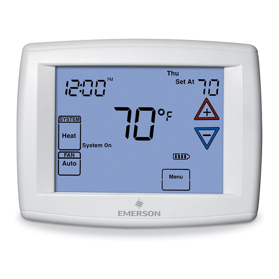
THERMOSTAT QUICK REFERENCE Home Screen Description Figure 2 – Home Screen Display Room Temperature Day of Week Set Temperature Time of Day Temperature UP/Down used for System modifying set point Switch as well as to navigating the menus Enters user-friendly Switch program into the schedule... -
Page 5: Installer Configuration Menu
INSTALLER/CONFIGURATION MENU To enter the menu: Press the Menu touch key . Press and hold for 5 seconds the Installer Config touch key . This displays menu item #1 in the table below . Press to advance to the next menu item or to return to a previous menu item . - Page 6 INSTALLER/CONFIGURATION MENU 1) This control can be configured for: the backlight on continuously . Selecting dL Off will turn SS1 – Single Stage System the backlight on momentarily after any key is pressed . HP1 – Heat Pump with one stage of compressor When C terminal is not powered (battery only), dL On (2 heat/1 cool) enables the momentary backlight whenever a key is...
- Page 7 INSTALLER/CONFIGURATION MENU 23 Select Fast Second Stage ON or OFF – In the run 20) Heat Temperature Limit Range – This feature adjusts mode, with the fast Heat feature enabled (FA Heat On), if the highest setpoint temperature for heat . The default the Heat setpoint temperature is manually raised by 3°F setting is 99°F .
-
Page 8: Operating Your Thermostat
OPERATING YOUR THERMOSTAT IMPORTANT! Choose the Fan Setting (Auto or On) Manual Operation (Bypassing the Program) Programmable Thermostats Fan Auto is the most commonly selected setting and runs the fan only when the heating or cooling system is on . Press and the HOLD button and adjust the tempera- Fan On selection runs the fan continuously for increased air... -
Page 9: Programming
PROGRAMMING Automatic Schedule Fill in the blank schedule on the next page then: This feature provides a method to program every day with Enter the Heating Program the most popular time and temperature profile using one key 1) Press the Menu button and then press Set Schedule . press . - Page 10 Energy Saving Factory Pre-Program The 1F97-1277 thermostats are programmed with the energy saving settings shown in the table below for all days of the week . If this program suits your needs, simply set the thermostat clock and press the RUN button .
-
Page 11: Wired Remote Temperature Sensing
PROGRAMMING Wired Remote Temperature Sensing Weight of Remote Reading: One remote temperature sensor can be installed indoor or When in view schedule mode the weight of the indoor remote sensor will be shown in the left actual temperature digits des- outdoor and connected to the thermostat by a maximum cable length of 100 meters (300 ft) . -
Page 12: Troubleshooting
First item in Configuration Earlier model of thermostat refer to 37-6814D . Menu is not SS1 or HP1 White-Rodgers is a business of Emerson Electric Co. The Emerson logo is a www.white-rodgers.com trademark and service mark www.emersonclimate.com of Emerson Electric Co.