Table of Contents
Advertisement
Save these instructions for future use!
FAILURE TO READ AND FOLLOW ALL INSTRUCTIONS
CAREFULLY BEFORE INSTALLING OR OPERATING THIS
CONTROL COULD CAUSE PERSONAL INJURY AND/OR
PROPERTY DAMAGE.
APPLICATIONS
THERMOSTAT APPLICATION GUIDE
Thermostat
Thermostat
Configuration
Applications
Options
Gas, Oil, Electric, Heat Only,
Single Stage 1
Cool Only or Heat/Cool
No Heat Pump (SS1)
Systems, 2 or 3 wire Hydronic
Multi Stage 2
Zone (Hot Water or Steam)
No Heat Pump (MS2)
Systems, 24 Volt or Millivolt
Heat Pump 1
Single Stage Compressor Heat
Single Stage
Pump Systems - up to 2 Stages
Compressor Heat
Aux ./Emergency Heat
Pump (HP1)
Heat Pump 2
Two Stage or Two Compressor
Two Stage or Two
Heat Pump systems - up to 2
Compressor Heat
Stages Aux ./Emergency Heat
Pump (HP2)
SPECIFICATIONS
Electrical Rating:
Battery Power . . . . . . . . . . . . . . . . . . . . . . . . . . mV to 30 VAC, NEC Class II, 50/60 Hz or DC
Input-Hardwire . . . . . . . . . . . . . . . . . . . . . . . . . 20 to 30 VAC
Terminal Load . . . . . . . . . . . . . . . . . . . . . . . . . . . . . 1 .5A per terminal, 2 .5A maximum all terminals combined
Setpoint Range . . . . . . . . . . . . . . . . . . . . . . . . . . . . 45 to 99°F (7 to 37°C)
Rated Differentials:
Heat (SS1, MS2) . . . . . . . . . . . . . . . . . . . . . . . 0 .6°F
Cool (SS1, MS2) . . . . . . . . . . . . . . . . . . . . . . . . 1 .2°F
Heat Pump (HP1, HP2) . . . . . . . . . . . . . . . . . . 1 .2°F
Emer Heat (HP1, HP2) . . . . . . . . . . . . . . . . . . . 0 .6°F
Operating Ambient . . . . . . . . . . . . . . . . . . . . . . . . . . 32°F to +105°F (0 to +41°C)
Operating Humidity . . . . . . . . . . . . . . . . . . . . . . . . . 90% non-condensing max .
Shipping Temperature Range . . . . . . . . . . . . . . . . . -40 to +150°F (-40 to +65°C)
Dimensions Thermostat . . . . . . . . . . . . . . . . . . . . . . 4-9/16"H x 5-13/16"W x 1-3/16"D
CAUTION
!
To prevent electrical shock and/or equipment damage,
disconnect electric power to system at main fuse or
circuit breaker box until installation is complete.
Index
Installation
Wiring Diagrams
Thermostat Quick Reference
Installer Configuration Menu
Operating Your Thermostat
Programming
Troubleshooting
Big Blue Commercial Universal Thermostat
with Damper or Economizer Control and
Automatic Heat/Cool Changeover Option
Installation and Operating Instructions
Model
1F95-1280
Maximum
W/ Economizer
Stages
Max. Stage
Heat/Cool
Heat/Cool
1/1
1/2
2/2
2/3
3/1
3/2
4/2
4/3
Fast
ATTENTION: MERCURY NOTICE
This product does not contain mercury . However, this prod-
uct may replace a product that contains mercury .
Mercury and products containing mercury must not be
discarded in household trash . Do not touch any spilled mer-
Page
cury . Wearing non-absorbent gloves, clean up any spilled
mercury and place in a sealed container . For proper disposal
2
of a product containing mercury or a sealed container of
3
spilled mercury, place it in a suitable shipping container .
4
Refer to www.thermostat-recycle.org for location to send
5
the product containing mercury .
9
10
14
www .white-rodgers .com
www .emersonclimate .com
Single Stage, Multi-Stage, Heat Pump
Programming Choices
7 Day
5/1/1 Day
1F95-1280
Slow
1 .5°F
1 .7°F
1 .7°F
1 .7°F
Non-Programmable
PART NO. 37-7292A
Replaces 37-6978C
1134
Advertisement
Table of Contents

Related Manuals for Emerson 1F95-1280


Summary of Contents for Emerson 1F95-1280
-
Page 1: Specifications
Installation and Operating Instructions Save these instructions for future use! FAILURE TO READ AND FOLLOW ALL INSTRUCTIONS Model Programming Choices CAREFULLY BEFORE INSTALLING OR OPERATING THIS CONTROL COULD CAUSE PERSONAL INJURY AND/OR 1F95-1280 7 Day 5/1/1 Day Non-Programmable PROPERTY DAMAGE. APPLICATIONS 1F95-1280... -
Page 2: Installation
. 7 . Carefully line the thermostat up with the base and snap into place . Figure 1 – Thermostat Base Multi-Stage 1F95-1280 Battery Location 2 "AA" alkaline batteries are included in the thermostat at the factory with a battery tag to prevent power drainage . -
Page 3: Wiring Diagrams
WIRING DIAGRAMS Figure 2 – Single Stage or Multi-Stage System (No Heat Pump) with Single Transformer System Single Stage 1 Call for cool No Output Call for heat No output Installer (SS1) Configuration Menu selects 24 volt “O” or “B” for common “Call for Service”... -
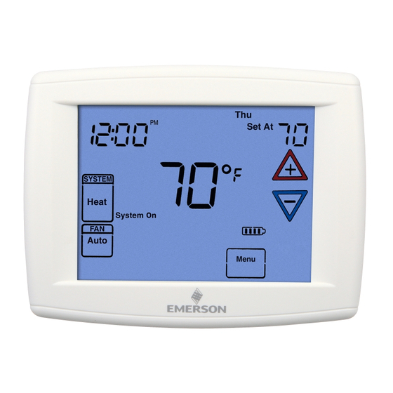
Page 4: Thermostat Quick Reference
THERMOSTAT QUICK REFERENCE Home Screen Description Figure 8 – Home Screen Display Room Temperature Day of Week Set Temperature/Humidity Time of Day Note: If is displayed, the Temperature thermostat is battery powered. UP/Down used for System When battery power remaining modifying setpoint Switch is approximately half,... -
Page 5: Installer/Configuration Menu
INSTALLER/CONFIGURATION MENU To enter the menu: Press the Menu touch key . Press and hold for 5 seconds the Installer Config touch key . This displays screen reference #1 in the table below . Screen Reference numbers appear in top right corner of display . Press to advance to the next menu item or to return to a previous menu item . - Page 6 INSTALLER/CONFIGURATION MENU CONFIGURATION MENU Screen Press Displayed Comments Press Reference Factory to select from Number (Default) listed options (60) Cd 0-99 Selects compressor off delay in seconds, dF selected On (80) AO -5 - 79 Selects Auxiliary Heat cut out temperature . This item appears if HP1 or HP2 is selected and outdoor sensor is installed and enabled .
- Page 7 INSTALLER/CONFIGURATION MENU 14 . Select °F or °C Readout – Changes the display readout 23 . Cool Temperature Limit Range – This feature adjusts to Celsius or Fahrenheit as required . the lowest setpoint temperature for cool . The default setting is 45°F .
- Page 8 INSTALLER/CONFIGURATION MENU The Fast Cool feature operates the cooling stages in the If indoor temperature drops below 45° because of a pos- same manner as Fast Heat, On or Off when the tempera- sible heat pump malfunction, the thermostat will turn off ture is lowered below the room setting .
-
Page 9: Operating Your Thermostat
Choose the Fan Setting (Auto or On or Prog) 5 minutes. There are three fan features on the 1F95-1280: 1 . Fan Auto/On – Traditional Fan Settings Heating Press Fan to select Auto or On . The most commonly 1 . -
Page 10: Manual Operation For Non-Programmable Mode
OPERATING YOUR THERMOSTAT Program Override (Temporary Override) Auto: Auto Changeover is used in areas where both heating and cooling may be required on the same day . AUTO allows Press keys to adjust the temperature . This will over- the thermostat to automatically select heating or cooling ride the temperature setting for a (default) four hour override depending on the indoor temperature and the selected heat period . -
Page 11: Automatic Schedule
Energy Saving Factory Pre-Program The 1F95-1280 thermostats are programmed with the energy saving settings shown in the table below for all days of the week . If this program suits your needs, simply set the thermostat clock and press the RUN key . - Page 12 The Heating and Cooling Program schedules below allow you to pencil in your own program times and temperatures . The 1F95-1280 comes configured for 7 day programming and can also be configured for 5+1+1 programming (see configura- tion section) .
-
Page 13: Wired Remote Temperature Sensing
PROGRAMMING Wired Remote Temperature Sensing Example: Local sensor temperature is 80° and the remote sensor is 70° . One remote temperature sensor can be installed indoor or If weight is selected H4, the averaged temperature of 72° will outdoor and connected to the thermostat by a maximum be displayed . -
Page 14: Troubleshooting
TROUBLESHOOTING Reset Operation Note: When thermostat is reset, installer configuration menu settings and programming will reset to factory settings . If a voltage spike or static discharge blanks out the display or causes erratic thermostat operation, you can reset the thermo- stat by removing the wires from terminals R and C (do not short them together) and removing batteries for 2 minutes . - Page 15 NOTES...
- Page 16 HOMEOWNER HELP LINE: 1-800-284-2925 White-Rodgers is a division of Emerson Electric Co . The Emerson logo is a www.white-rodgers.com trademark and service mark www.emersonclimate.com of Emerson Electric Co .