Table of Contents
Advertisement
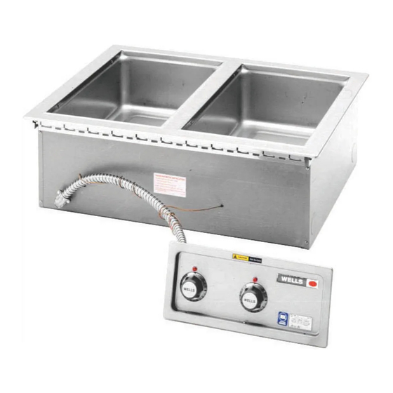
MOD-200T
MOD-200TDN
IMPORTANT: DO NOT DISCARD THIS MANUAL
This manual is considered to be part of the appliance and is to be given to the OWNER or
MANAGER of the restaurant, or to the person responsible for TRAINING OPERATORS of
this appliance. Additional manuals are available from your WELLS DEALER.
THIS MANUAL MUST BE READ AND UNDERSTOOD BY ALL PERSONS USING OR
INSTALLING THIS APPLIANCE. Contact your WELLS DEALER if you have any
questions concerning installation, operation or maintenance of this equipment.
Z16298 Rev. (-)
2M-
p/n
WELLS BLOOMFIELD, LLC
10 Sunnen Dr., St. Louis, MO 63143
telephone: 314-678-6314
fax: 314-781-2714
www.wellsbloomfield.com
OWNERS MANUAL
THERMOSTAT or DIGITAL
M200, M227, MOD200, MOD227
M300, M327, MOD300, MOD327
M400, M427, MOD400, MOD427
M500, M527, MOD500, MOD527
BUILT-IN WELL
MODULAR
WARMERS
with
INFINITE,
CONTROLS
MODELS
Includes
INSTALLATION
USE & CARE
EXPLODED VIEW
PARTS LIST
WIRING DIAGRAM
M011C.02
011C
12
0816
Advertisement
Table of Contents

Related Manuals for Wells M200


Summary of Contents for Wells M200
- Page 1 Additional manuals are available from your WELLS DEALER. THIS MANUAL MUST BE READ AND UNDERSTOOD BY ALL PERSONS USING OR INSTALLING THIS APPLIANCE. Contact your WELLS DEALER if you have any questions concerning installation, operation or maintenance of this equipment.
-
Page 2: Warranty
LIMITED WARRANTY STATEMENT Unless otherwise specified, all commercial cooking Unless otherwise specified, all commercial cooking The prices charged by Wells Bloomfield for its products The prices charged by Wells Bloomfield for its products equipment manufactured by WELLS BLOOMFIELD, LLC is are based upon the limitations in this warranty. -
Page 3: Table Of Contents
PARTS & SERVICE CUSTOMER SERVICE DATA INTRODUCTION Thank You for purchasing this Wells Bloomfield appliance. Thank You for purchasing this Wells Bloomfield appliance. Proper installation, professional operation and consistent maintenance of this appliance will ensure that it gives you the very best performance and a long, economical service life. -
Page 4: Specifications
SPECIFICATIONS (Thermostat) AMPS 3ø MODEL VOLTS WATTS AMPS1ø MOD-200T 208 VAC 2480W 6.0A 6.0A 10.3A 11.9A MOD-200TD MOD-200TDM 240 VAC 3300W 6.9A 6.9A 11.9A 13.8A MOD-200TN 208 VAC 2480W 6.0A 6.0A 10.3A 11.9A MOD-200TDN MOD-200TDMN 240 VAC 3300W 6.9A 6.9A 11.9A 13.8A MOD-227TD... - Page 5 SPECIFICATIONS (Digital) AMPS 3ø MODEL VOLTS WATTS AMPS1ø M200CE M200E M200CED M200ED M200CED6 M200ED6 M200CEDM M200EDM M200CEDM6 M200EDM6 M200CEAF 208/240V 2,475 / 3,312 6.0 / 6.9 6.0 / 6.9 10.3 / 11.9 11.9 / 13.8 M200EAF M200CEAF6 M200EAF6 M227CEDM M227EDM M227CEDM6 M227EDM6 M227CEAF...
-
Page 6: Features & Operating Controls
FEATURES & OPERATING CONTROLS A. THERMOSTAT On thermostatically controlled warmers, power is applied to the INDICATOR heating element according to the control knob position and the actual LIGHT temperature at the temperature sensing thermobulb. The desired temperature is controlled by rotating the temperature control knob. -
Page 7: Precautions & General Information
Do not operate this appliance if the control panel is damaged. Call installation instructions are your Authorized Wells Service Agent for service. read and followed. Damage The technical content of this manual, including any wiring diagrams,... -
Page 8: Installation
INSTALLATION NOTE: DO NOT discard NOTE: DO NOT discard UNPACKING & INSPECTION UNPACKING & INSPECTION the carton or other packing materials until you have Carefully remove the appliance from the carton. Remove all protective inspected the appliance for plastic film, packing materials and accessories from the Appliance hidden damage and tested it before connecting electrical power or otherwise performing any for proper operation. - Page 9 INSTALLATION 3. For “top-mounted” warmers (i.e. warmers mounted from above the counter top): Verify that provided sealants are applied to the underside of the warmer top flange prior to setting the unit into the cutout. After installation, verify that the tabs on the Wellsloks are turned out to lock the warmer into the counter.
-
Page 10: Operation
NOT be used wet-to-dry or dry-to-wet unless they have been allowed to cool to room temperature between the change in wet or dry operation. CAUTION: Wells Manufacturing recommends operating WET for consistent SHOCK HAZARD food heating. DO NOT splash or pour water If your wet-operation warmer is allowed to run dry, turn it onto control panel or wiring. - Page 11 OPERATION (continued) AUTOFILL WARMERS continued DO NOT use autofill warmers in the dry mode. This may damage the water level sensor probe. NEVER turn the thermostat ON for the pan with the probe and fill tube unless the entire warmer unit is to be used in the wet mode.
-
Page 12: Cleaning Instructions
fire and/or electric shock hazard. Contact your Authorized Wells Service Agency to inspect warmer if water or grease contamination is suspected. Close drain valve. Add proper amount of warm water. Turn control... - Page 13 CLEANING INSTRUCTIONS WEEKLY CLEANING INSTRUCTIONS CAUTION: CHEMICAL BURN PREPARATIONS: Remove any insets, pans and/or adapter tops. HAZARD Drain or remove water from well if used for wet Deilimng chemicals may be Deilimng che operation. caustic. Wear appropriate personal protective equipment. FREQUENCY: Weekly, or whenever lime or scale is seen Follow cleaner manufacturer’s...
-
Page 14: Troubleshooting Suggestions
One or more pans of an auto-fill Blocked drain manifold Clean drain manifold unit do not fill There are no user-serviceable components in this appliance. In all instances of damage or malfunction, contact your Authorized Wells Service Agency for repairs. -
Page 15: Maintenance Instructions
Never use metal implements, wire brushes, abrasive scratch pads or steel wool to clean stainless steel. Warmer pans, insets and other vessels are subject to a harsher environment. Wells Manufacturing uses an very high quality stainless steel (#304DDQ) for our food warmer pans. -
Page 16: Model Number Identifications
MODEL NUMBER IDENTIFIER MOD200T, MOD200TD, MOD200TDM Built-In Modular Warmer Identifier M300CTDNMAF6 96” Capillary Tube Auto-Fill Manifold Narrow Drain T=Thermostat, E=Digital Niether = Infinite Corded 00= 20” Pan, 27=27” Pan Number of Pans M or MOD, same Standard Narrow Drain Auto-Fill Manifold Pan Assy w/ Auto-Fill Connec tion... -
Page 17: Exploded View & Parts List
EXPLODED VIEW & PARTS LIST “ T” units only See Detail Digital Controlled Units = AutoFill Units Only BUILT-IN MODULAR WARMERS SK2615, Rev. -, 8/15/12... - Page 18 PARTS LIST: M200-227 SERIES Model: Modular Warmers M200-227T, TD, TDM, TDMAF, TN, M200-227E, CE, ED, EDM, EDMAF, EN Fig No Part No Description Application P2-31869 SCREEN DRAIN ASSY WARMER DRAIN UNITS P2-Z14636 PAN ASSY 12X20 EAF W/TEE M200 DIGITAL P2-Z14647...
- Page 19 PARTS LIST: M200-227 SERIES Model: Modular Warmers M200-227T, TD, TDM, TDMAF, TN, M200-227E, CE, ED, EDM, EDMAF, EN Fig No Part No Description Application P2-40843 BRKT MTG THERMO INFINITE T-STAT & INFINITE UNITS P2-48176 BRKT THERMO MOD200TDM AUT T-STAT AUTOFILL...
- Page 20 PARTS LIST: M300-327 SERIES Model: Modular Warmers M300-327T, TD, TDM, TDMAF, TN, M300-327E, CE, ED, EDM, EDMAF, EN Fig No Part No Description Application P2-31869 SCREEN DRAIN ASSY WARMER DRAIN UNITS P2-Z14636 PAN ASSY 12X20 EAF W/TEE M300 DIGITAL P2-Z14647 PAN ASSY 12X27 EAF M327 DIGITAL P2-WL0064...
- Page 21 PARTS LIST: M300-327 SERIES Model: Modular Warmers M300-327T, TD, TDM, TDMAF, TN, M300-327E, CE, ED, EDM, EDMAF, EN Fig No Part No Description Application P2-37809 BRKT CONT MTG MOD 300 400 INFINITE UNITS P2-48586 BRKT THERMO MOD300T T-STAT P2-47863 BRKT THERMO MOD BMW ROHS T-STAT AUTOFILL 2E-306865 CONTROL LIQ LEVEL 208/240...
- Page 22 PARTS LIST: M400-427 SERIES Model: Modular Warmers M400-427T, TD, TDM, TDMAF, M400-427E, CE, ED, EDM, EDMAF Fig No Part No Description Application P2-31869 SCREEN DRAIN ASSY WARMER DRAIN UNITS P2-Z14636 PAN ASSY 12X20 EAF W/TEE M400 DIGITAL P2-Z14647 PAN ASSY 12X27 EAF M427 DIGITAL WS-503893 PAN ASSY 200-500TDM A/F...
- Page 23 PARTS LIST: M400-427 SERIES Model: Modular Warmers M400-427T, TD, TDM, TDMAF, M400-427E, CE, ED, EDM, EDMAF Fig No Part No Description Application 2T-38968 THERMO K TYPE T-STAT UNITS 2T-46551 THERMO CTRL 96IN CAP T-STAT UNITS w/ 96IN CAPILLARY THERMO CTRL W/AUX 2T-45917 T-STAT UNITS, AUTOFILL WARMERS...
- Page 24 PARTS LIST: M500-527 SERIES Model: Modular Warmers M500-527T, TD, TDM, TDMAF, M500-527E, CE, ED, EDM, EDMAF Fig No Part No Description Application P2-31869 SCREEN DRAIN ASSY WARMER DRAIN UNITS P2-Z14636 PAN ASSY 12X20 EAF W/TEE M500 DIGITAL P2-Z14647 PAN ASSY 12X27 EAF M527 DIGITAL WS-503893 PAN ASSY 200-500TDM A/F...
- Page 25 PARTS LIST: M500-527 SERIES Model: Modular Warmers M500-527T, TD, TDM, TDMAF, M500-527E, CE, ED, EDM, EDMAF Fig No Part No Description Application KNOB CONTROL ASSY 2R-44373 INFINITE UNITS WARMERS 2R-40498 KNOB ASSY MOD 100DT T-STAT UNITS 2E-46529 SOLENOID VALVE 1/4NPT 240 AUTOFILL UNITS P2-48285 BRKT THERMO MOD400...
- Page 26 EXPLODED VIEW: DETAIL A Nameplate SOME ITEMS ARE A REPRESENTATION OF THE ACTUAL APPREANCE DUE TO YOUR SPECIFIC MODEL. Detail MODE - EAF Digital Control Fab Warmer IL2523, Rev. -, 8/21/12...
- Page 27 2M-Z14527 GRAPHIC M400/427E M400/427E, M400/427EAF 2M-Z14529 GRAPHIC M500/527E M500/527E, M500/527EAF 2E-Z1858 SWITCH-LIGHTED AUTO-FILL 2C-33935 SCREW 6ABX5/16 PH PAN SMS P2-Z14494 CONTROL PANEL M200/227E M200-227E P2-Z14496 CONTROL PANEL M200/227EAF M200-227EAF P2-Z14522 CONTROL PANEL M300/327E M300-327E P2-Z14524 CONTROL PANEL M300/327EAF M300-327EAF P2-Z14525...
- Page 28 WIRING DIAGRAM: Infinite Control Units WIRING DIAGRAM FOR MODULAR 200 WARMER 208/240V SINGLE PHASE SER. NO. WM 1000 & UP ELEMENT SAFETY THERMO (2) INFINITE SWITCH (2) PILOT LIGHT (2) SINGLE PHASE VOLTS AMPS TERM. BLOCK 10.0 REV. I PN 2M-31222 MOD200 &...
- Page 29 WIRING DIAGRAM: Infinite Control Units WIRING DIAGRAM FOR MODULAR 400 WARMER 208/240V SINGLE PHASE OR THREE PHASE SER. NO. MOD-400 MW 1250 & UP ELEMENT SAFETY THERMO (4) SINGLE PHASE INFINITE SWITCH (4) PILOT LIGHT (4) THREE PHASE NOM. AMPS PER LINE THREE PHASE VOLTS SINGLE...
- Page 30 WIRING DIAGRAM: Electronically Control Units NOTES: WIRING DIAGRAM MOD200E 1) TEMPERATURE AND WATER LEVEL SENSOR WIRES ROUTE SEPARATELY IN SMALLER CONDUIT. 2) GROUND TO EARTH USING SUPPLIED STUD IN CONTROL BOX. PROBE 3) OPTIONAL WATER LEVEL CONTROL: WIRES 19 & 35 SHOULD BE CAPPED IF NOT USED.
- Page 31 WIRING DIAGRAM: Electronically Control Units NOTES: WIRING DIAGRAM MOD400E 3 12 101 1) TEMPERATURE AND WATER LEVEL SENSOR WIRES ROUTE SEPARATELY IN SMALLER CONDUIT. 2) GROUND TO EARTH USING SUPPLIED STUD IN CONTROL BOX. 1 10 102 3) OPTIONAL WATER LEVEL CONTROL: WIRES 19 & 35 SHOULD BE CAPPED IF NOT USED. PROBE 3&...
- Page 32 WIRING DIAGRAM: MOD200 Thermostat Control Units WIRING DIAGRAM FOR MOD 200T, 227T WARMER 208/240V, SINGLE PHASE HEATING ELEMENT (2) PILOT LIGHT (2) THERMOSTAT (2) WIRE CONNECTOR SINGLE VOLTS WATTS PHASE 2480 11.9 3300 13.8 REV. C P/N 2M-40844 TERM. BLOCK M200T &...
- Page 33 WIRING DIAGRAM: MOD300 Thermostat Control Units WIRING DIAGRAM FOR MOD 300T, 327T WARMER 208/240V, SINGLE & THREE PHASE HEATING ELEMENT (3) PILOT LIGHT PILOT LIGHT (3) THERMOSTAT (3) TERMINAL BOARD WIRE CONNECTOR SINGLE PHASE THREE PHASE SINGLE VOLTS PHASE 10.3 10.3 10.3 17.9...
-
Page 34: Wiring Diagram
WIRING DIAGRAM: MOD400 Thermostat Control Units WIRING DIAGRAM FOR MOD 400T, 427T WARMER 208/240V, SINGLE & THREE PHASE HEATING ELEMENT (4) PILOT LIGHT (4) THERMOSTAT (4) TERMINAL BOARD SINGLE PHASE WIRE CONNECTOR THREE PHASE SINGLE VOLTS PHASE 14.5 14.5 23.8 11.3 17.8 17.8... - Page 35 WIRING DIAGRAM: MOD400 Thermostat Control Units WIRING DIAGRAM FOR MOD400TDM & 427TDM WARMER W/AUTO WATER FILL 208/240V, SINGLE & THREE PHASE HEATING ELEMENT (4) WATER PAN PILOT LIGHT PROBE WIRE MALE/FEMALE CONNECTOR THERMOSTAT THERMOSTAT CONNECTOR PROBE LOW WATER CONTROL TERM. BLOCK WATER FILL VALVE COMMON INPUT...
- Page 36 WIRING DIAGRAM: MOD500 Thermostat Control Units WIRING DIAGRAM FOR MOD 500T, 527T WARMER 208/240V, SINGLE & THREE PHASE HEATING ELEMENT (5) PILOT LIGHT (5) THERMOSTAT (5) TERMINAL BOARD SINGLE PHASE WIRE CONNECTOR THREE PHASE SINGLE VOLTS PHASE 14.6 14.6 19.5 29.8 16.9 16.9...
- Page 37 WIRING DIAGRAM: MOD500 Thermostat Control Units WIRING DIAGRAM FOR MOD 500TDM AND 527TDM WARMER W/AUTO WATER FILL 208/240V, SINGLE & THREE PHASE HEATING ELEMENT (5) PILOT LIGHT THERMOSTAT WIRE CONNECTOR COMMON INPUT SINGLE PHASE ALTERNATE LOW WATER CONTROL LOW WATER CONTROL PROBE TERM.
-
Page 38: Parts & Service
PARTS & SERVICE DESCRIPTION PART NO. Always use an inset. DO NOT place food directly into the warmer pan. ADAPTERS & INSETS ADAPTER TOP, convert 12” x 20” warmer to hold two 7 qt. insets WS-21502 ADAPTER TOP, convert 12” x 20” warmer to hold two 4 qt. -
Page 39: Customer Service Data
1¾” thick WS-22592* your Wells authorized service agency, or call: WELLSLOK EXTENSION KIT, for UL LISTED 12” x 20” warmers only, adapt to wood counter up to 1¾” thick WS-22593* Wells Bloomfield, LLC... - Page 40 WELLS BLOOMFIELD, LLC 10 Sunnen Dr., St. Louis, MO 63143 telephone: 314-678-6314 fax: 314-781-2714 www.wellsbloomfield.c om...