Honda EG5000X Owner's Manual
Hide thumbs
Also See for EG5000X:
- Owner's manual (51 pages) ,
- Owner's manual (45 pages) ,
- Owner's manual (45 pages)

Related Manuals for Honda EG5000X


Summary of Contents for Honda EG5000X
- Page 1 Owner’s Manual GENERATOR EG5000X o2001-2009 Honda Motor Co., Ltd. -All Rights Reserved...
- Page 2 The engine exhaust from this product contains chemicals known to the State of California to cause cancer, birth defects or other reproductive harm. Exhaust contains poisonous carbon monoxide gas that can build up to dangerous levels in closed areas. Breathing carbon monoxide can cause unconsciousness or death. Never run the generator in a closed, or even partly closed area where people may be present.
- Page 3 INTRODUCTION Congratulations on your selection of a Honda generator. We are certain you will be pleased with your purchase of one of the finest generators on the market. We want to help you get the best results from your new generator and to operate it safely.
- Page 4 A FEW WORDS ABOUT SAFETY Your safety and the safety of others are very important. And using this generator safely is an important responsibility. To help you make informed decisions about safety, we have provided operating procedures and other information on labels and in this manual.
-
Page 5: Table Of Contents
CONTENTS GENERATOR SAFETY ................Safety Label Locations ............... Important Safety Information ............COMPONENT IDENTIFICATION .............. CONTROLS ....................10 Engine Switch ..................10 Starter Grip ..................10 Fuel Valve Lever ................. 11 Choke Lever ..................11 Circuit Breaker ................... - Page 6 MAINTENANCE ..................26 The Importance of Maintenance ............26 Maintenance Safety ................27 Maintenance Schedule ..............28 Engine Oil Change ................29 Air Cleaner Service ................30 Fuel Sediment Cup Cleaning ............31 Spark Plug Service ................
-
Page 7: Generator Safety
GENERATOR SAFETY SAFETY LABEL LOCATIONS These labels warn you of potential hazards that can cause serious injury. Read them carefully. If a label comes off or becomes hard to read, contact your Honda generator dealer for a replacement. California type... -
Page 8: Important Safety Information
IMPORTANT SAFETY INFORMATION Honda generators are designed to give safe and dependable service if operated according to instructions. Read and understand this owner’s manual before operating your generator. You can help prevent accidents by being familiar with your generator’s controls and by observing safe operating procedures. - Page 9 Electric Shock Hazards The generator produces enough electric power to cause a serious shock or electrocution if misused. Using a generator or electrical appliance in wet conditions, such as rain or snow, or near a pool or sprinkler system, or when your hands are wet, could result in electrocution.
-
Page 10: Component Identification
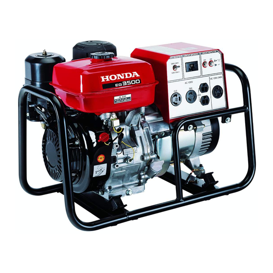
COMPONENT IDENTIFICATION VOLTAGE SELECTOR SWITCH ENGINE SWITCH CHOKE LEVER AC CIRCUIT BREAKER FUEL VALVE LEVER CIRCUIT PROTECTORS AC RECEPTACLES CARBURETOR DRAIN SCREW OIL FILLER CAP SEDIMENT OIL DRAIN PLUG STARTER GRIP ENGINE SERIAL NUMBER... - Page 11 FUEL TANK CAP GROUND TERMINAL MUFFLER AIR CLEANER SPARK PLUG FRAME SERIAL NUMBER Record the engine and frame serial numbers and date of purchase for your future reference. Refer to these serial numbers when ordering parts and when making technical or warranty inquiries (see page Frame serial number: Engine serial number:...
-
Page 12: Controls
CONTROLS ENGINE SWITCH To start and stop the engine. Switch position: OFF: To stop the engine. To start and run the engine. ENGINE SWITCH STARTER GRIP To start the engine, pull the starter grip lightly until you feel resistance, then pull briskly in the direction of the arrow as shown below. Do not allow the starter grip to snap back against the engine. -
Page 13: Fuel Valve Lever
FUEL VALVE LEVER The fuel valve is located on the carburetor. When the fuel valve lever is in the ON position, fuel is allowed to flow from the fuel tank to the carburetor. Be sure to return the fuel valve lever to the OFF position after stopping the engine. -
Page 14: Circuit Breaker
CIRCUIT BREAKER The AC circuit breaker will automatically switch OFF if there is a short circuit or an overload of the generator at the AC receptacle. If the AC circuit breaker is switched OFF automatically, check that the appliance is working properly and does not exceed the rated load capacity of the AC circuit before switching the AC circuit breaker ON again. -
Page 15: Ground Terminal
GROUND TERMINAL The generator ground terminal is connected to the frame of the generator, the metal non-current-carrying parts of the generator, and the ground terminals of each receptacle. Before using the ground terminal, consult a qualified electrician, electrical inspector, or local agency having jurisdiction for local codes or ordinances that apply to the intended use of the generator. -
Page 16: Voltage Selector Switch (Dual Voltage System)
VOLTAGE SELECTOR SWITCH (DUAL VOLTAGE SYSTEM) The voltage selector switches the main power carrying windings of the generator to produce ‘‘120V ONLY’’ or ‘‘120/240V’’. If a 240V appliance is connected to the 4-prong receptacle, the switch must be in the ‘‘120/ 240V’’... -
Page 17: Generator Use
GENERATOR USE CONNECTIONS TO A BUILDING ELECTRICAL SYSTEM Connections for standby power to a building electrical system must be made by a qualified electrician. The connection must isolate the generator power from utility power, and must comply with all applicable laws and electrical codes. A transfer switch, which isolates generator power from utility power, is available through authorized Honda generator dealers (see page Improper connections to a building electrical system can allow... -
Page 18: Ac Applications
AC APPLICATIONS Before connecting an appliance or power cord to the generator: Make sure that it is in good working order. Faulty appliances or power cords can create a potential for electrical shock. If an appliance begins to operate abnormally, becomes sluggish, or stops suddenly, turn it off immediately. -
Page 19: Ac Operation
AC OPERATION Start the engine (see page Turn the voltage selector switch to either position. With the voltage selector switch in the ‘‘120/240V’’ position, you can use the 120V and 120/240V receptacles simultaneously. If you are NOT using the 120/240V receptacle, then select the ‘‘120V ONLY’’ position. Switch ON the AC circuit breaker. -
Page 20: Ac Receptacle Selection
AC RECEPTACLE SELECTION The control panel, shown below, has a voltage selector switch and five receptacles. Receptacle 4 and 5 comprise one 240-volt receptacle with two powered terminals. RECEPTACLE RECEPTACLE RECEPTACLE RECEPTACLE RECEPTACLE Power Producing Circuits This generator is equipped with two power generating circuits. When the voltage selector switch is in the 120V/240V position, each of the two power producing circuits supplies power to specific receptacles. - Page 21 Voltage Selector Switch The power available to each receptacle depends on the position of the voltage selector switch. Switch Position Receptacle Available Power 120V ONLY 30A at 120V 20A at 120V 20A at 120V 20A at 120V None 120V/240V 18.8A at 120V 18.8A at 120V 18.8A at 120V 18.8A at 240V...
-
Page 22: High Altitude Operation
HIGH ALTITUDE OPERATION At high altitude, the standard carburetor air/fuel mixture will be too rich. Performance will decrease, and fuel consumption will increase. A very rich mixture will also foul the spark plug and cause hard starting. Operation at an altitude that differs from that at which this engine was certified, for extended periods of time, may increase emissions. -
Page 23: Pre-Operation Check
PRE-OPERATION CHECK Before beginning your pre-operation checks, be sure the generator is on a level surface and the engine switch is in the OFF position. ENGINE OIL Engine oil is a major factor affecting engine performance and service life. Non-detergent and 2-stroke engine oils will damage the engine and are not recommended. -
Page 24: Refueling
REFUELING With the engine stopped, remove the fuel tank cap and check the fuel level. Refill the fuel tank if the fuel level is low. Gasoline is highly flammable and explosive. You can be burned or seriously injured when handling fuel. Stop the engine and keep heat, sparks, and flame away. -
Page 25: Fuel Recommendations
FUEL RECOMMENDATIONS This engine is certified to operate on regular unleaded gasoline with a pump octane rating of 86 or higher. Never use stale or contaminated gasoline or an oil/gasoline mixture. Avoid getting dirt or water in the fuel tank. You may use regular unleaded gasoline containing no more than 10% ethanol (E10) or 5% methanol by volume. -
Page 26: Starting The Engine
STARTING THE ENGINE STARTING THE ENGINE For your safety, do not operate the generator in an enclosed area such as a garage. Your generator’s exhaust contains poisonous carbon monoxide gas that can collect rapidly in an enclosed area and cause illness or death. -
Page 27: Stopping The Engine
STOPPING THE ENGINE STOPPING THE ENGINE In an emergency: To stop the engine in an emergency, turn the engine switch to the OFF position. In normal use: Turn the AC circuit breaker to the OFF position. Turn the engine switch to the OFF position. Turn the fuel valve lever to the OFF position. -
Page 28: Maintenance
MAINTENANCE THE IMPORTANCE OF MAINTENANCE Good maintenance is essential for safe, economical, and trouble free operation. It will also help reduce air pollution. Improper maintenance, or failure to correct a problem before operation, can cause a malfunction in which you can be seriously hurt or killed. -
Page 29: Maintenance Safety
MAINTENANCE SAFETY Some of the most important safety precautions follow. However, we cannot warn you of every conceivable hazard that can arise in performing maintenance. Only you can decide whether or not you should perform a given task. Failure to properly follow maintenance instructions and precautions can cause you to be seriously hurt or killed. -
Page 30: Maintenance Schedule
MAINTENANCE SCHEDULE First Every Every Every REGULAR SERVICE PERIOD (3) Each month 3 months 6 months year ITEM Perform at every indicated month or operating hour inter- 20 Hrs. 50 Hrs. 100 Hrs. 300 Hrs. val, whichever comes first. Engine oil Check level Change Air cleaner... -
Page 31: Engine Oil Change
ENGINE OIL CHANGE Drain the oil while the engine is warm to assure rapid and complete draining. Remove the drain plug and sealing washer, remove the oil filler cap, and drain the oil. Reinstall the drain plug and sealing washer. Tighten the plug securely. -
Page 32: Air Cleaner Service
AIR CLEANER SERVICE A dirty air cleaner will restrict air flow to the carburetor. To prevent carburetor malfunction, service the air cleaner regularly. Service more frequently when operating the generator in extremely dusty areas. Using gasoline or flammable solvent to clean the air filter can cause a fire or explosion. -
Page 33: Fuel Sediment Cup Cleaning
FUEL SEDIMENT CUP CLEANING The sediment cup prevents dirt or water that may be in the fuel tank from entering the carburetor. If the engine has not been run for a long time, the sediment cup should be cleaned. Turn the fuel valve lever to the OFF position. Remove the sediment cup, O-ring, and filter. -
Page 34: Spark Plug Service
SPARK PLUG SERVICE Recommended spark plugs: BPR5ES (NGK) W16EPR-U (DENSO) To ensure proper engine operation, the spark plug must be properly gapped and free of deposits. If the engine has been running, the muffler will be very hot. Be careful not to touch the muffler. -
Page 35: Spark Arrester Maintenance
Check that the spark plug washer is in good condition, and thread the spark plug in by hand to prevent cross-threading. After the spark plug is seated, tighten with a spark plug wrench to compress the washer. If installing a new spark plug, tighten 1/2 turn after the spark plug seats to compress the washer. -
Page 36: Storage
STORAGE Storage Preparation Proper storage preparation is essential for keeping your generator trouble-free and looking good. The following steps will help to keep rust and corrosion from impairing your generator’s function and appearance, and will make the engine easier to start when you use the generator again. - Page 37 Use the following table to determine the appropriate storage procedure. STORAGE TIME RECOMMENDED SERVICE PROCEDURE TO PREVENT HARD STARTING Less than 1 month No preparation required 1 to 2 months Fill with fresh gasoline and add gasoline stabilizer *. Fill with fresh gasoline and add gasoline 2 months to 1 year stabilizer *.
- Page 38 Draining the Carburetor Float Bowl Gasoline is highly flammable and explosive. You can be burned or seriously injured when handling fuel. Stop the engine and keep heat, sparks, and flame away. Handle fuel only outdoors. Wipe up spills immediately. Turn the fuel valve lever to the OFF position. Drain the carburetor by loosening the drain screw.
-
Page 39: Coating The Engine Cylinder With Oil
Coating the Engine Cylinder with Oil Remove the spark plug (see page Pour a teaspoon (5 cc) of clean engine oil into the cylinder. Pull the starter grip several times to distribute the oil in the cylinder. Reinstall the spark plug. Slowly pull the starter grip until resistance is felt. -
Page 40: Storage Precautions
Storage Precautions If your generator will be stored with gasoline in the fuel tank and carburetor, it is important to reduce the hazard of gasoline vapor ignition. Select a well ventilated storage area away from any appliance that operates with a flame, such as a furnace, water heater, or clothes dryer. Also avoid any area with a spark-producing electric motor, or where power tools are operated. -
Page 41: Transporting
TRANSPORTING TRANSPORTING When transporting the generator, turn the engine switch and the fuel valve OFF. Keep the generator level to prevent fuel spillage. Fuel vapor or spilled fuel may ignite. -
Page 42: Troubleshooting
TROUBLESHOOTING When the engine will not start: Is there fuel in the Refill the fuel tank tank? (see page 22). Is there enough oil Add the recom- in the engine? mended oil (see page 21). Is the spark plug in Adjust the gap and good condition? dry the spark plug. - Page 43 No electricity at the AC receptacles: Is the AC circuit breaker Turn the AC circuit breaker ON (see page 17). NO DEFECTS Check the electrical ap- Take the generator to an pliance or equipment for authorized Honda generator any defects. dealer.
-
Page 44: Technical Information
TECHNICAL INFORMATION EMISSION CONTROL SYSTEM INFORMATION Source of Emissions The combustion process produces carbon monoxide, oxides of nitrogen, and hydrocarbons. Control of hydrocarbons and oxides of nitrogen are very important because, under certain conditions, they react to form photochemical smog when subjected to sunlight. Carbon monoxide does not react in the same way, but it is toxic. - Page 45 Problems That May Affect Emissions If you are aware of any of the following symptoms, have your engine inspected and repaired by your servicing dealer. Hard starting or stalling after starting. Rough idle. Misfiring or backfiring under load. Afterburning (backfiring). Black exhaust smoke or high fuel consumption.
- Page 46 Replacement Parts The emission control systems on your new Honda engine were designed, built, and certified to conform with applicable emission regulations. We recommend the use of Honda Genuine parts whenever you have maintenance done. These original-design replacement parts are manufactured to the same standards as the original parts, so you can be confident of their performance.
-
Page 47: Air Index
AIR INDEX (Models certified for sale in California) An Air Index Information label is applied to engines certified to an emission durability time period in accordance with the requirements of the California Air Resources Board. The bar graph is intended to provide you, our customer, the ability to compare the emissions performance of available engines. -
Page 48: Specifications
SPECIFICATIONS Dimensions Model EG5000X Type Non-California type California type (AN type) (AC type) Power product description code Length 25.7 in (653 mm) Width 18.9 in (480 mm) Height 19.1 in (485 mm) 19.6 in (497 mm) Dry mass [weight] 146.6 lbs (66.5 kg) -
Page 49: Consumer Information
General Manager can help. Almost all problems are solved in this way. If you are dissatisfied with the decision made by the dealership’s management, contact the Honda Power Equipment Customer Relations Office. You can write to: American Honda Motor Co., Inc. -
Page 50: Honda Publications
Parts Catalog This manual provides complete, illustrated parts lists. Available through your Honda dealer. Accessories Catalog Your authorized Honda power equipment dealer offers a wide selection of accessories (optional equipment) to make your generator even more useful. Visit www.hondapowerequipment.com/products/accessories/ and click on Generators and Welders to see the entire catalog of... -
Page 51: Wiring Diagram
WIRING DIAGRAM... -
Page 52: Index
INDEX COMPONENT IDENTIFICATION .............. CONTROLS ....................10 Choke Lever ..................11 Circuit Breaker ..................12 Circuit Protector ................. 12 Engine Switch ..................10 Fuel Valve Lever ................. 11 Ground Terminal ................13 Oil Alert System ................ - Page 53 PRE-OPERATION CHECK ............... . 21 Engine Oil ................... 21 Fuel Recommendations ..............23 Refueling .................... . 22 GENERATOR SAFETY ................IMPORTANT SAFETY INFORMATION ..........SAFETY LABEL LOCATIONS .............. STARTING THE ENGINE ................ . 24 STOPPING THE ENGINE ................ .
- Page 54 MEMO...
- Page 55 2eY1400.2009.03 31ZC2771 " Printed in Japan 00X31-ZC2-7710...